Downloaded 992 times


![9AEI306.59-60 20
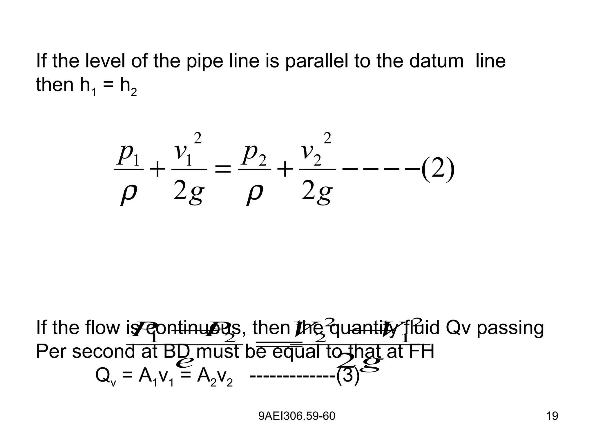
2 2
2 1 1 2
2
( ) (4)
g
V V P P
e
− = − − − − − −
2
1 2 2
1
(5)
A
v v mv
A
= = − − − −
[ ]2
1
(5) (4)
A
m substituting in
A
=Q
2 2 21 2 1 2
2 2 2
2 ( ) 2 (( )2
(1 )
(1 )
g p p g p pg
v m v x
mρ ρ
− −
− = → =
−
1 2
2 2
2 ( )1
(1 )
g P P
v
m ρ
−
=
−](https://image.slidesharecdn.com/flowmeasurement-170121021644/75/Flow-measurement-20-2048.jpg)


![9AEI306.67-68 140
• I2
R= a (vρ +b)1/2
• V=[I4
R2
/a2
–b] / ρ
• Temperature and resistance of a wire kept constant
• Velocity measured by measuring current (i), through
the heated wire](https://image.slidesharecdn.com/flowmeasurement-170121021644/75/Flow-measurement-140-2048.jpg)


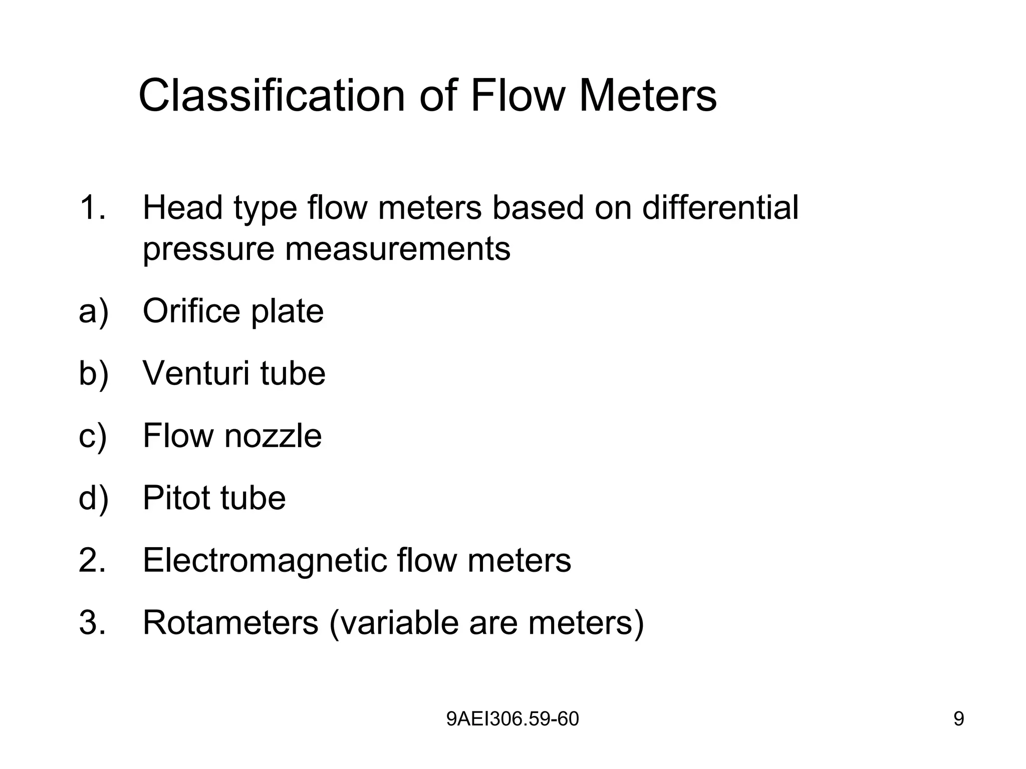
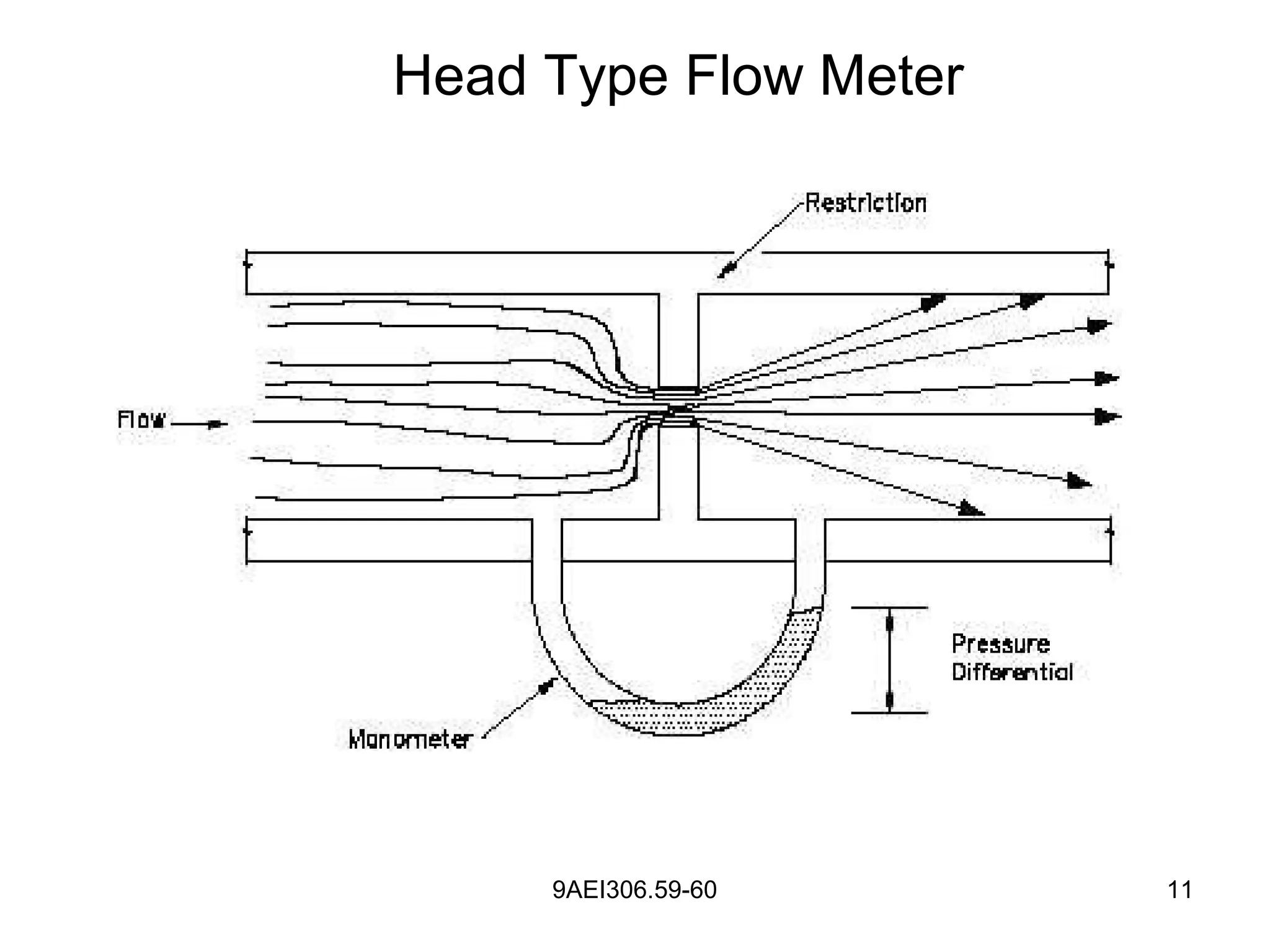
Flow measurement devices are important for applications like water supply, agriculture, industry, construction and laboratories. They are classified based on whether they measure quantity (volume) or rate of flow. Common head-type flow meters that measure rate of flow using differential pressure include orifice plates, venturi tubes and pitot tubes. Orifice plates create a pressure drop by restricting flow through a circular opening. Venturi tubes follow Bernoulli's principle where a converging section increases flow velocity and decreases pressure.


