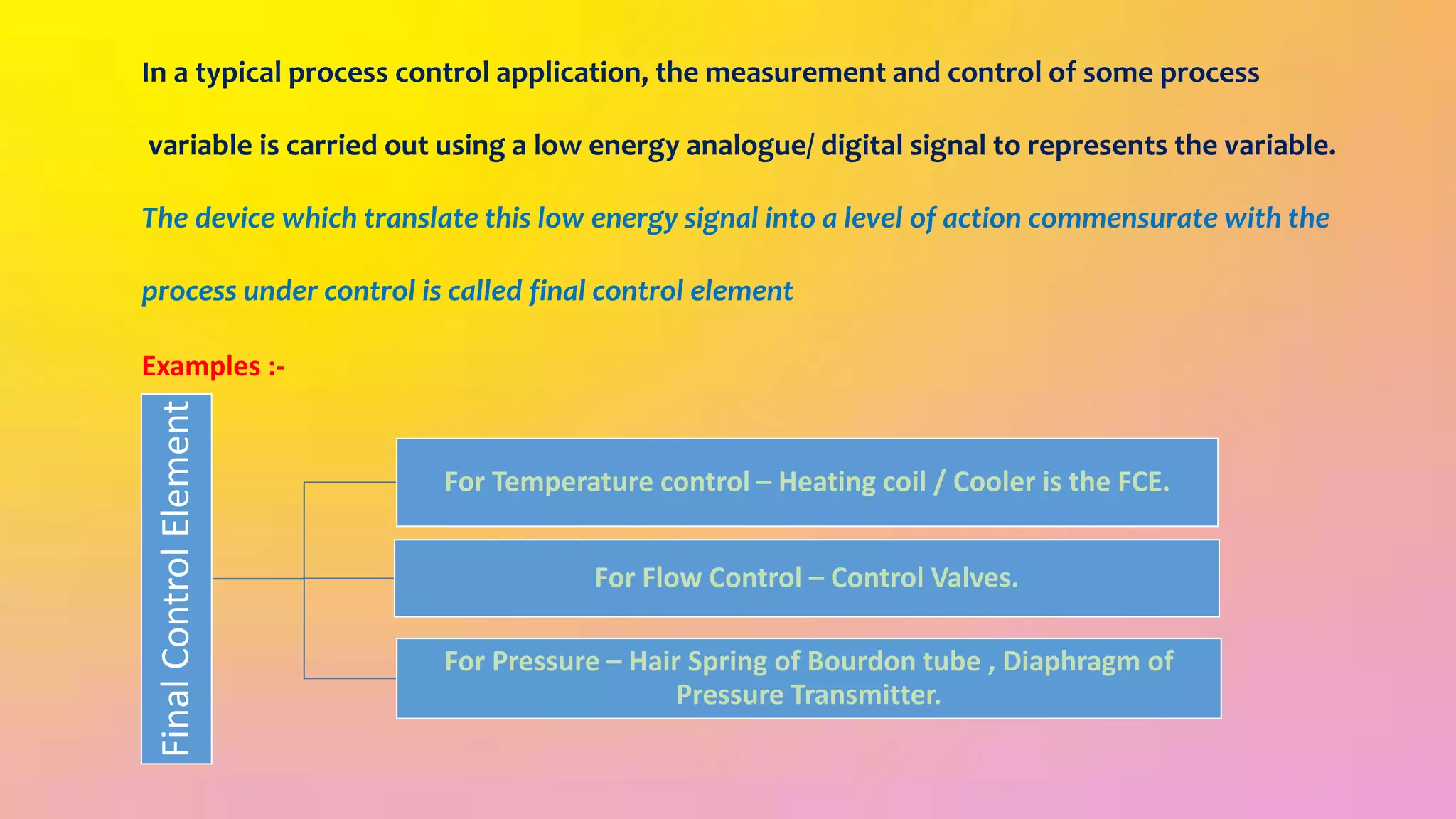
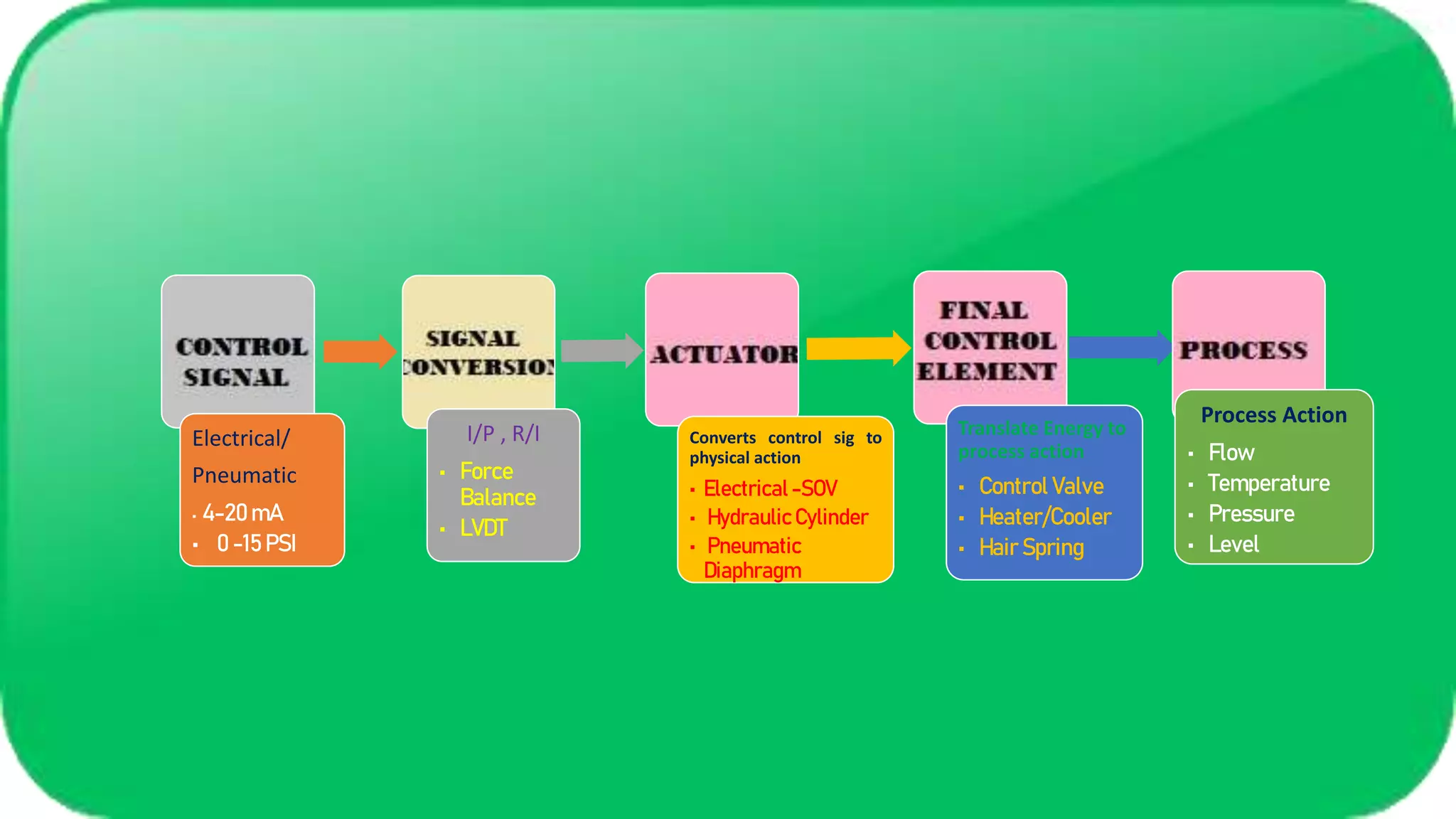
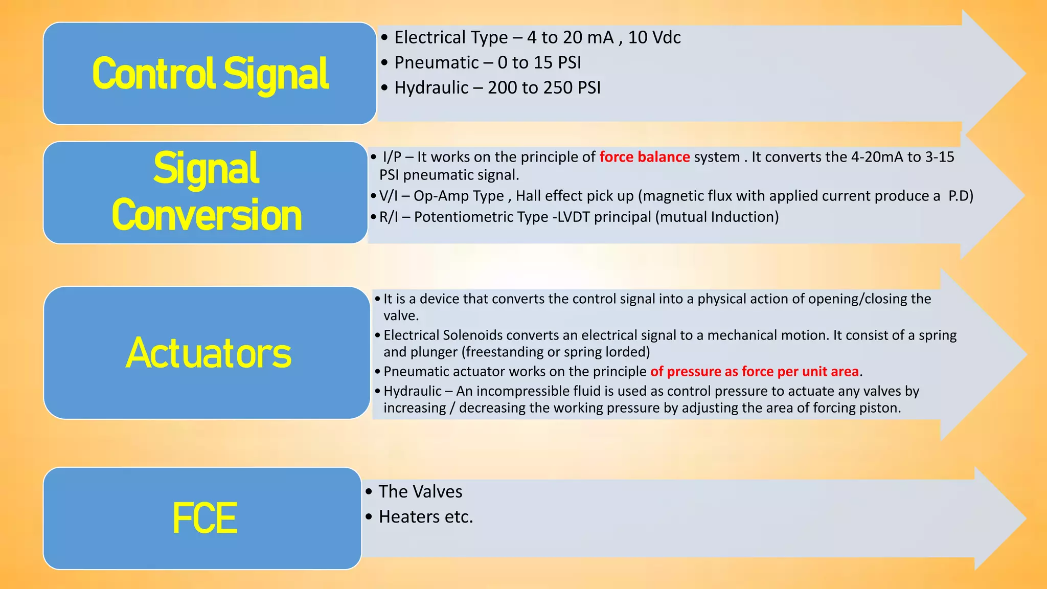
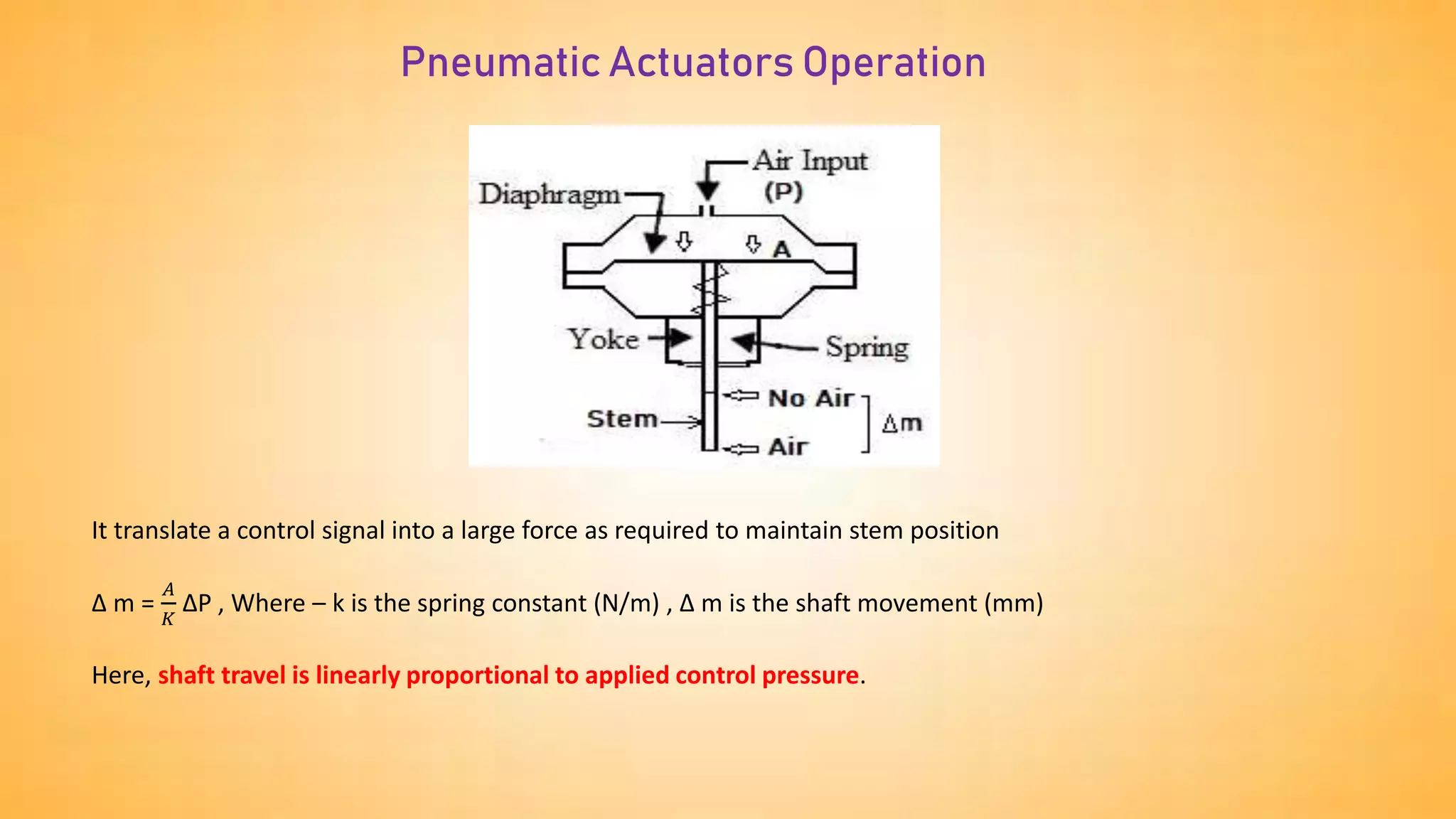
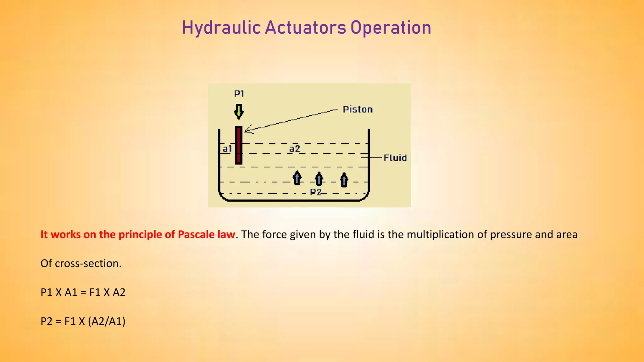
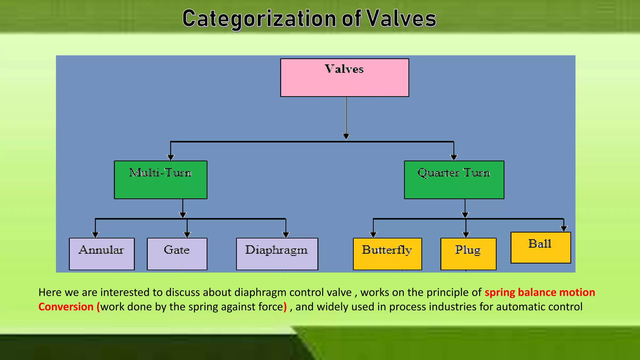
The document defines and provides examples of a final control element. It then describes how final control elements work to translate a low-energy control signal into a physical action that controls a process variable. Specifically, it discusses how different types of actuators (electrical, pneumatic, hydraulic) receive an input control signal and use it to manipulate a final control element like a control valve or heater to impact temperature, flow, pressure, or other process variables. Finally, it focuses on diaphragm control valves as a commonly used final control element, describing their main parts and operating principles.
3. In a typical process control application, the measurement and control of some process
variable is carried out using a low energy analogue/ digital signal to represents the variable.
The device which translate this low energy signal into a level of action commensurate with the
process under control is called final control element
Examples :-
Final
Control
Element
For Temperature control – Heating coil / Cooler is the FCE.
For Flow Control – Control Valves.
For Pressure – Hair Spring of Bourdon tube , Diaphragm of
Pressure Transmitter.
5. Electrical/
Pneumatic
• 4-20 mA
• 0 -15 PSI
I/P , R/I
• Force
Balance
• LVDT
Converts control sig to
physical action
• Electrical -SOV
• Hydraulic Cylinder
• Pneumatic
Diaphragm
Translate Energy to
process action
• Control Valve
• Heater/Cooler
• Hair Spring
Process Action
• Flow
• Temperature
• Pressure
• Level
6. • Electrical Type – 4 to 20 mA , 10 Vdc
• Pneumatic – 0 to 15 PSI
• Hydraulic – 200 to 250 PSI
Control Signal
• I/P – It works on the principle of force balance system . It converts the 4-20mA to 3-15
PSI pneumatic signal.
•V/I – Op-Amp Type , Hall effect pick up (magnetic flux with applied current produce a P.D)
•R/I – Potentiometric Type -LVDT principal (mutual Induction)
Signal
Conversion
•It is a device that converts the control signal into a physical action of opening/closing the
valve.
•Electrical Solenoids converts an electrical signal to a mechanical motion. It consist of a spring
and plunger (freestanding or spring lorded)
•Pneumatic actuator works on the principle of pressure as force per unit area.
•Hydraulic – An incompressible fluid is used as control pressure to actuate any valves by
increasing / decreasing the working pressure by adjusting the area of forcing piston.
Actuators
• The Valves
• Heaters etc.
FCE
7. Pneumatic Actuators Operation
It translate a control signal into a large force as required to maintain stem position
∆ m =
𝐴
𝐾
∆P , Where – k is the spring constant (N/m) , ∆ m is the shaft movement (mm)
Here, shaft travel is linearly proportional to applied control pressure.
8. Hydraulic Actuators Operation
It works on the principle of Pascale law. The force given by the fluid is the multiplication of pressure and area
Of cross-section.
P1 X A1 = F1 X A2
P2 = F1 X (A2/A1)
9. Here we are interested to discuss about diaphragm control valve , works on the principle of spring balance motion
Conversion (work done by the spring against force) , and widely used in process industries for automatic control
10. The concept of control valves was 1st introduced by Sir Leonardo da Vinci by sketching a moving plug valve mechanism,
Later in the 18th century Sir James Watt introduced the concept of moving stem valve for his fly-ball governor , which
was developed to regulate the speed of his steam engine. Automatic control valves has three main Parts-
Valve Actuator
Valve Positioner
Valve Body
The mostly used diaphragm control valves are of two types – Air to Open (Fail Close) and Air to Close (Fail Open).
Further Control valves are of direct acting (output tends to increase as signal increases) and reverse acting ( output
decreases as signal increases)
11. Air to open valves are normally held closed by the spring and require air pressure (a control signal) to open them
– they open progressively as the air pressure increases.
Air to close valves are valves which are held open by the valve spring and require air pressure to move them
towards the closed position.
The reason for the two types of valves is to allow fail safe operation. In the event of a plant instrument air failure,
it is important that all control valves fail in a safe position (e.g. an exothermic reactor’s feed valves (or, perhaps,
just one of the valves) should fail closed (air to open) and its coolant system valves fail open (air to close).
The type of valve used obviously impacts on what a controller has to do – changing the type of valve would mean
that the controller would need to move the manipulation in the opposite direction.
To simplify things in this course we shall assume that we are always using air to open valves – an increase in
control action will cause the valve to open and the flow through it to increase.
12. The Various Accessories of Valves are –
Bonnet
Yolk
Valve Plug
Seat Ring
Plug Stem
Diaphragm
Diaphragm Cage
Packing Spacer
Spring
Plug Pin
Scale
13.
14. As you can see from this diagram, there is a lot going on inside an electronic positioner. We have not just one,
but two control algorithms working together to maintain proper valve position:
one monitoring and controlling pressure applied to the actuator (compensating for changes in air supply pressure
that might otherwise affect the valve’s position) and the other monitoring and controlling stem position itself, sending
a cascaded control signal to the pressure control components.
The command signal (sent from the process loop controller, PLC, or other control system) tells the positioner where
the
valve stem should be positioned. The first controller inside the positioner (PI) calculates how much air pressure at the
actuator should be needed to achieve the requested stem position.
The next controller (PID) drives the I/P (current-to-pressure) converter as much as necessary to achieve that
pressure.
If anything causes the valve stem to not be at the commanded position, the two controllers inside the positioner work
together to force the valve to its proper position.
Not only do electronic valve positioners achieve superior position control when compared to mechanical valve
positioners, but their array of sensors and digital communication ability provides a new level of diagnostic data
both to maintenance personnel and the supervising control system (if programmed to monitor and act on this data).