Downloaded 538 times
![GUIDED BY :SUMAN SWAMI
PREPARED BY :SUCHITRA [10EEBEC081]
SUMAN SIDH [10EEBEC083]
SUSHMA TANWAR](https://image.slidesharecdn.com/temperaturebased-140307201532-phpapp02/85/Temperature-based-speed-control-of-fan-1-320.jpg)
![GUIDED BY :SUMAN SWAMI
PREPARED BY :SUCHITRA [10EEBEC081]
SUMAN SIDH [10EEBEC083]
SUSHMA TANWAR](https://image.slidesharecdn.com/temperaturebased-140307201532-phpapp02/75/Temperature-based-speed-control-of-fan-1-2048.jpg)
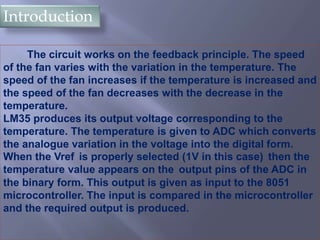


This document describes a temperature controlled fan speed controller circuit. The circuit uses an LM35 temperature sensor to monitor temperature. It sends the analog temperature reading to an ADC which converts it to a digital signal for a microcontroller. The microcontroller compares the temperature to set limits and controls the speed of a DC fan motor using PWM to vary the duty cycle and fan speed. It aims to efficiently cool components by increasing fan speed as temperature rises and decreasing it as temperature falls.


![Tamperature controlled fan_project_report[1]](https://cdn.slidesharecdn.com/ss_thumbnails/tamperaturecontrolledfanprojectreport1-170912121052-thumbnail.jpg?width=640&height=640&fit=bounds)


