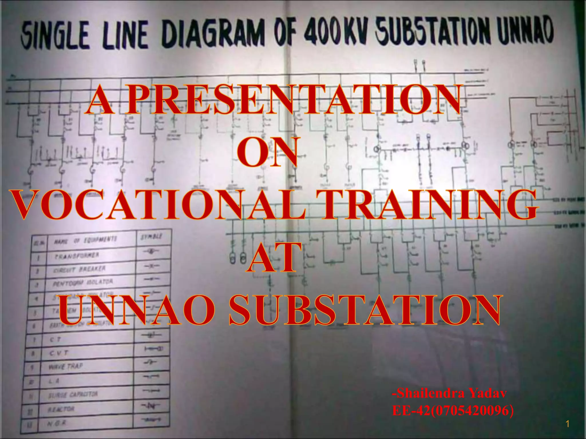
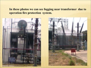
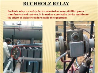
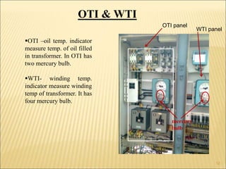
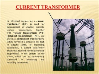
This document provides an overview of the Unnao substation located in India. It describes:
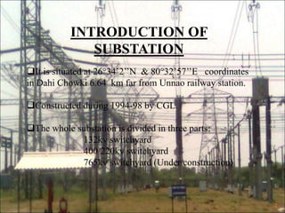
1. The substation was constructed between 1994-1998 and is divided into 132kV, 400/220kV, and 765kV switchyards.
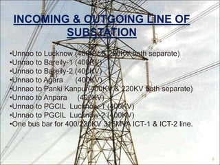
2. It has multiple incoming and outgoing transmission lines connecting it to other substations in the region operating at 400kV and 220kV.
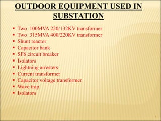
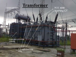
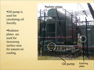
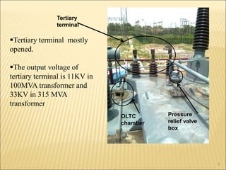
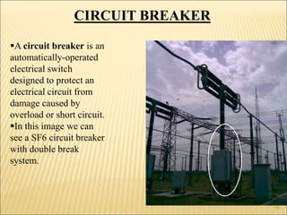
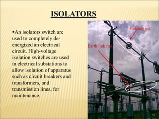
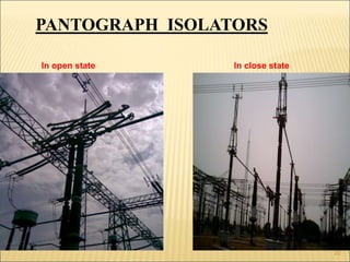
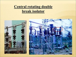
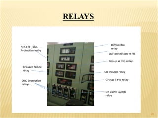
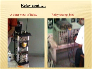
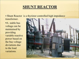
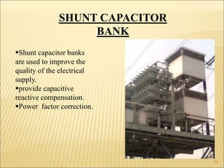
3. The substation contains various outdoor equipment used for transmission including transformers, shunt reactors, capacitor banks, circuit breakers, and other switchgear.


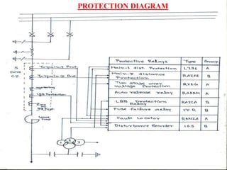


![protection of transmission lines[distance relay protection scheme]](https://cdn.slidesharecdn.com/ss_thumbnails/os-exe3-23-may2011-sr-i-776s21tr-lineprotection-120425095503-phpapp02-thumbnail.jpg?width=640&height=640&fit=bounds)


