Downloaded 149 times
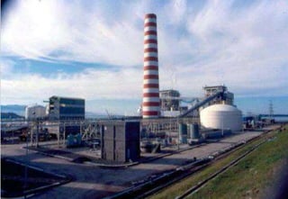
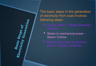
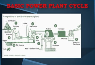
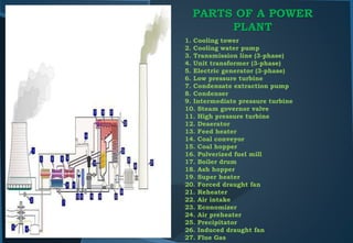
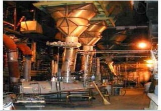


The document summarizes the 4 week industrial training that the author completed at NTPC Limited Badarpur Thermal Power Station from June 3rd to July 4th, 2013. The training involved visiting various divisions of the power plant including the Electrical Maintenance Department I (EMD-I), Electrical Maintenance Department II (EMD-II), and Control and Instrumentation Department (C&I). The document then provides details on the basic process of electricity generation from coal, the major components of a power plant, electrical equipment, and laboratories in the Control and Instrumentation Department.