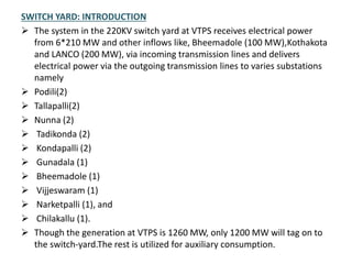
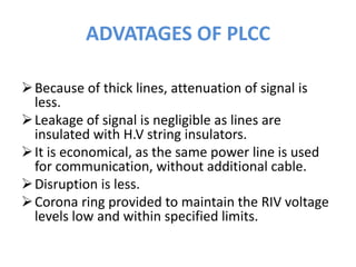
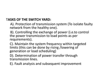
STUDY OF 220KV SWITCH
YARD
Batch Members
 KATTA NARESH 08NA1A0225
 KUMPATI VASU 08NA1A0229
 N.HARISH SAGAR 08NA1A0238
P.MANI KUMAR 08NA1A0244
 S.T.KUMAR 08NA1A0250
 V.NARENDRA BABU 08NA1A0253
INTRODUCTION OF VTPS
• 1. INTRODUCTION OF DR.NTTPS (VTPS)
• Food, clothing and shelter were the basic needs of
mankind till lately but now we can say electricity has become a part
of basic needs. Life without electricity has become unimaginable.
There are three ways for the generation of electricity thermal, hydel
under nuclear. In India, majority of the power is produced utilizing
thermal energy
• Dr. N T T P S came into existence in 1977 in between
Ibrahimpatnam & Kondapalli villages. It is unique in its layout and
numerous authors expects such as easy operation and
maintenance. There are three stages in Dr.NTTPS the total capacity
of the three stages her is 1260MW.
• This report gives a detailed report about the various equipment
and their working in the switch yard
SWITCH YARD: INTRODUCTION
 The system in the 220KV switch yard at VTPS receives electrical power
from 6*210 MW and other inflows like, Bheemadole (100 MW),Kothakota
and LANCO (200 MW), via incoming transmission lines and delivers
electrical power via the outgoing transmission lines to varies substations
namely
 Podili(2)
 Tallapalli(2)
 Nunna (2)
 Tadikonda (2)
 Kondapalli (2)
 Gunadala (1)
 Bheemadole (1)
 Vijjeswaram (1)
 Narketpalli (1), and
 Chilakallu (1).
 Though the generation at VTPS is 1260 MW, only 1200 MW will tag on to
the switch-yard.The rest is utilized for auxiliary consumption.
KONDAPALLI S.S
VTPS 2 FEEDERS
LANCO
132 VJW 132KV
FEEDERS
EQUIPEMENTS IN SWITCH YARD
An electrical substation is an assemblage of
electrical components including
 bus bars
Isolators
 circuit breakers
 transformers
 lighting arresters
 instrument transformers….etc.
The switch-yard comprises of the following
equipment:
• 28 bays which include 6GTs,5 STs, 2 bypass,
one bus coupler and 15 feeders.
• Station battery system.
• Centralized air conditioning system with
connecting switchgear.
INSULATORS
o The flexible ACSR conductors of transmission line and substation bus burs are
supported on string insulators. The rigid tubular bus bars in SS are supported on
Solid insulators/post insulators.
Materials used for insulators
o Ceramic (Porcelain, Steatite)
o Glass-fiber reinforced epoxy resin rod covered by sheds made of silicon-rubber)
o
PROPRETIES OF INSULATORS:
o High Electrical resistance of insulator material in order to avoid leakage currents to
earth.
o High Mechanical strength to with stand conductor load, wind load etc.’
o It should be non porous and free from impurities and cracks.
o High ratio of puncture strength to flashover.
• Three distinct types of Insulators are used in transmission systems and substations:
• String Insulators (Suspension or tension) for supporting ACSR or AAAC conductors. The string
insulator consists of several identical Ball and socket type disc insulators in series with end
fitting on across arm side and conductor side.
• a) Solid post insulators. Are used in the following applications and named accordingly.
• Post Insulators for support
• Shaft insulators
• Operating rod insulators
• Hollow porcelain insulator for transformers bushing, SF6 GIS bushing, CTs, CVTS, PTs, CBs
chambers.
•
• For DISTRIBUTION NETWORKS & SS:
• Pin type insulator (for LT & HT)
• Shackle insulators
• Safety insulators
• The important requirement of air-insulation and porcelain insulators in EHV substations and
transmission lines are
BUS BARS
• The choice of the bus bars scheme for a
substation depends upon the degree of
reliability and economic justification. The
degree of reliability is evaluated by
determining the continuity of service and
possible faults.
TYPES OF BUS BARS ARRANGEMENTS:
SINGLE BUSBAR ARRANGEMENT
SSSSSSSSI
This system is used for 132 KV
substations. It is cheapest among all
the others bus bars. It is totally shut
down in case of a fault.
DOUBLE BUS BARS:
• This system is costlier then a single bus bars system. One bus
can serve as reserve, which is used during maintenance or
fault. It is used for 220 KV sub stations.
DOUBLE BUS BAR WITH TRANSFER BUS
• This system has additional flexibility for operation. We can
take shut down on a breaker without interrupting the
transmission line. It is used for critical 220KV substation.
CIRCUIT BREAKERS
• Circuit breaker is automatic switching device which can
carrying normal current and switching in & out normal
loads
• Interrupt short circuiting currents
• Able to performer auto reclose duty.
• Classification of Circuit breaker:
• Based on VOLTAGE
• Low-less than 1kv
• Medium-1kv to 52kv
• High/Extra High-66kv to 765kv
• Ultra High-above 765kv
• Based on LOCATION
• Indoor
• Outdoor
• Based on INTERRUPTING MEDIUM
• Air break………Air break Circuit breaker…………(ACB)
• Air blast………Air blast Circuit breaker…………..(ABCB)
• Bulk oil………….. Bulk oil Circuit breaker……….(BOCB)
• Minimum oil………..Minimum oil Circuit breaker………….(MOCB)
• SF6 gas insulated…………….SF6 Circuit breaker
• Vacuum…………… Vacuum Circuit breaker………………(VCB)
• Selection of a CB depends on:
• Type of application
• Rated voltage, current
• Its breaking capacity(fault level of the installation)
• Auto-reclose duty cycle
•
SF6 CIRCUIT BREAKER
Opening operation:
• Opening is affected by pulling the insulating rod (201),
piston rod (111), puffer cylinder (110) moving contact,
moving arc contact (107) and the nozzle (105).After
contacts wipe the stationary and moving and contact (104),
(107) separate, there by generating arc. During down ward
movement the gas in puffer chamber builds up and high
pressure gas flows through nozzle and quenches the arc.
Closing Operation:
• In closing operation, insulating rod (201) is pulled up and
the parts move in the reverse direction of opening
operation. And also SF6 gas taken in to puffer chamber.
NAME PLATE DETAILS
• RATINGS
• Type 200-SFM-40A
• Rated Voltage 245kV
• Rated Insulation Level 1050kVp
• Rated Frequency 50Hz
• Rated Normal Current 3150A
• Rated Short Circuit Breaking Current
• R.M.S Value for A.C Component 40kA
• Percentage D.C Component 50%
• Rated Short Circuit Making Current 100kA
• Rated Break Time 60ms (3 cycles)
• Rated Short time Current 40kA for 3 Sec.
• Operating Sequence 0-0.3S-CO-3 min co
• Rated TRV 364kVp
• Operating Mechanism Spring closing
• Pneumatic tripping
• Operating Pressure (air) 16.5kg/cm2
• SF6 Gas Pressure 6.0 kg/cm2 at 20c
• Applicable Standard IEC-62271-100
• Opening Time 30ms
• Closing Time 100ms
• Pole Discrepancy (Between Poles) 3.3ms
• The center to center distance between phases is generally 4500mm.but cabn be changed to suit users specific requirement
ADVANTAGES OF SF6 CB
• Mostly widely used in EHV application
• Low operating noise
• Simple construction & compact size
• Easy installation, inspection & maintenance.
• SF6 is identified as a green house gas.
INSTRUMENT TRANSFORMERS
INSTRUMENT TRANSFORMERS:
• Current transformer
• Potential transformer
• Current transformer: Current transformer are
used for supplying the current circuits of
indicating instruments (ammeters, watt
meters etc) recording meters (energy meters
etc) and protective relays.
• CT is ideally a short circuited transformer
where the secondary terminal voltage is zero,
and the magnetizing current is negligible.
• Ip*Np =Is*Ns
• Ratio error
• Phase angle error
• Composite error
CURRENT TRANSFORMER
VOLTAGE TRANSFORMER:
• These instrument are used for supplying the voltage circuit of
indicating instruments, meters, and protective relay.
• All voltage transformer are designed for a standard secondary
voltage of 110v, 110/1.732 (63.5)
• For voltage transformers at the following is valid:
• Ep/Es=Np/Ns
• Actual voltage ratio =Primary volts/secondary volts
Voltage transformer errors:
• A) voltage ratio error
• B) Phase angle error.
• The errors at which the VTs operate depend on its burden and
primary voltage
POTENTIAL TRANSFORMER
POWER LINE CARRIER
COMMUNICATION (PLCC)
PLCC is economical and reliable method of
communication system.
• The Equipment in a PLCC system are :
• 1. Trap (Wave trap)
• 2. Coupling capacitor
• 3. Earth switch
• 4. Drainage coil
• 5. Lighting arrester
• 6. Line matching unit
• Carrier wave in PLCC is radio frequency waves of
frequencies between 20KHZ to500KHZ.
PLCC SCHEMATIC DIAGRAM
ADVATAGES OF PLCC
Because of thick lines, attenuation of signal is
less.
Leakage of signal is negligible as lines are
insulated with H.V string insulators.
It is economical, as the same power line is used
for communication, without additional cable.
Disruption is less.
Corona ring provided to maintain the RIV voltage
levels low and within specified limits.
TASKS OF THE SWITCH YARD:
A). Protection of transmission system (To isolate faulty
network from the healthy one).
B). Controlling the exchange of power (i.e.to control
the power transmission to load points as per
requirements).
C). Maintain the system frequency within targeted
limits (this can be done by rising /lowering of
generation or load scheduling)
D). Determination of power transfer through
transmission lines.
E). Fault analysis and subsequent improvement
CONCLUSION
This project ‘’OVER ALL EQUIPMENT OF 220KV SWITCH YARD
IN DR.NTTPS” is constructed in such a way that every one can
understand about the working and principle of 220kv
switchyard equipments. This also explains about battery
system used as secondary purpose.
Further automatic devices can be provider to insulators
like automatic OFF if insulator and giving the signal etc.
ANY QUERIES?
THANK YOU

220kv-switch-yard-ppt.pptx

  • 1.
    STUDY OF 220KVSWITCH YARD
  • 2.
    Batch Members  KATTANARESH 08NA1A0225  KUMPATI VASU 08NA1A0229  N.HARISH SAGAR 08NA1A0238 P.MANI KUMAR 08NA1A0244  S.T.KUMAR 08NA1A0250  V.NARENDRA BABU 08NA1A0253
  • 3.
    INTRODUCTION OF VTPS •1. INTRODUCTION OF DR.NTTPS (VTPS) • Food, clothing and shelter were the basic needs of mankind till lately but now we can say electricity has become a part of basic needs. Life without electricity has become unimaginable. There are three ways for the generation of electricity thermal, hydel under nuclear. In India, majority of the power is produced utilizing thermal energy • Dr. N T T P S came into existence in 1977 in between Ibrahimpatnam & Kondapalli villages. It is unique in its layout and numerous authors expects such as easy operation and maintenance. There are three stages in Dr.NTTPS the total capacity of the three stages her is 1260MW. • This report gives a detailed report about the various equipment and their working in the switch yard
  • 4.
    SWITCH YARD: INTRODUCTION The system in the 220KV switch yard at VTPS receives electrical power from 6*210 MW and other inflows like, Bheemadole (100 MW),Kothakota and LANCO (200 MW), via incoming transmission lines and delivers electrical power via the outgoing transmission lines to varies substations namely  Podili(2)  Tallapalli(2)  Nunna (2)  Tadikonda (2)  Kondapalli (2)  Gunadala (1)  Bheemadole (1)  Vijjeswaram (1)  Narketpalli (1), and  Chilakallu (1).  Though the generation at VTPS is 1260 MW, only 1200 MW will tag on to the switch-yard.The rest is utilized for auxiliary consumption.
  • 5.
    KONDAPALLI S.S VTPS 2FEEDERS LANCO 132 VJW 132KV FEEDERS
  • 6.
    EQUIPEMENTS IN SWITCHYARD An electrical substation is an assemblage of electrical components including  bus bars Isolators  circuit breakers  transformers  lighting arresters  instrument transformers….etc.
  • 7.
    The switch-yard comprisesof the following equipment: • 28 bays which include 6GTs,5 STs, 2 bypass, one bus coupler and 15 feeders. • Station battery system. • Centralized air conditioning system with connecting switchgear.
  • 8.
    INSULATORS o The flexibleACSR conductors of transmission line and substation bus burs are supported on string insulators. The rigid tubular bus bars in SS are supported on Solid insulators/post insulators. Materials used for insulators o Ceramic (Porcelain, Steatite) o Glass-fiber reinforced epoxy resin rod covered by sheds made of silicon-rubber) o PROPRETIES OF INSULATORS: o High Electrical resistance of insulator material in order to avoid leakage currents to earth. o High Mechanical strength to with stand conductor load, wind load etc.’ o It should be non porous and free from impurities and cracks. o High ratio of puncture strength to flashover.
  • 9.
    • Three distincttypes of Insulators are used in transmission systems and substations: • String Insulators (Suspension or tension) for supporting ACSR or AAAC conductors. The string insulator consists of several identical Ball and socket type disc insulators in series with end fitting on across arm side and conductor side. • a) Solid post insulators. Are used in the following applications and named accordingly. • Post Insulators for support • Shaft insulators • Operating rod insulators • Hollow porcelain insulator for transformers bushing, SF6 GIS bushing, CTs, CVTS, PTs, CBs chambers. • • For DISTRIBUTION NETWORKS & SS: • Pin type insulator (for LT & HT) • Shackle insulators • Safety insulators • The important requirement of air-insulation and porcelain insulators in EHV substations and transmission lines are
  • 10.
    BUS BARS • Thechoice of the bus bars scheme for a substation depends upon the degree of reliability and economic justification. The degree of reliability is evaluated by determining the continuity of service and possible faults. TYPES OF BUS BARS ARRANGEMENTS:
  • 11.
    SINGLE BUSBAR ARRANGEMENT SSSSSSSSI Thissystem is used for 132 KV substations. It is cheapest among all the others bus bars. It is totally shut down in case of a fault.
  • 12.
    DOUBLE BUS BARS: •This system is costlier then a single bus bars system. One bus can serve as reserve, which is used during maintenance or fault. It is used for 220 KV sub stations.
  • 13.
    DOUBLE BUS BARWITH TRANSFER BUS • This system has additional flexibility for operation. We can take shut down on a breaker without interrupting the transmission line. It is used for critical 220KV substation.
  • 14.
    CIRCUIT BREAKERS • Circuitbreaker is automatic switching device which can carrying normal current and switching in & out normal loads • Interrupt short circuiting currents • Able to performer auto reclose duty. • Classification of Circuit breaker: • Based on VOLTAGE • Low-less than 1kv • Medium-1kv to 52kv • High/Extra High-66kv to 765kv • Ultra High-above 765kv
  • 15.
    • Based onLOCATION • Indoor • Outdoor • Based on INTERRUPTING MEDIUM • Air break………Air break Circuit breaker…………(ACB) • Air blast………Air blast Circuit breaker…………..(ABCB) • Bulk oil………….. Bulk oil Circuit breaker……….(BOCB) • Minimum oil………..Minimum oil Circuit breaker………….(MOCB) • SF6 gas insulated…………….SF6 Circuit breaker • Vacuum…………… Vacuum Circuit breaker………………(VCB) • Selection of a CB depends on: • Type of application • Rated voltage, current • Its breaking capacity(fault level of the installation) • Auto-reclose duty cycle •
  • 16.
  • 17.
    Opening operation: • Openingis affected by pulling the insulating rod (201), piston rod (111), puffer cylinder (110) moving contact, moving arc contact (107) and the nozzle (105).After contacts wipe the stationary and moving and contact (104), (107) separate, there by generating arc. During down ward movement the gas in puffer chamber builds up and high pressure gas flows through nozzle and quenches the arc. Closing Operation: • In closing operation, insulating rod (201) is pulled up and the parts move in the reverse direction of opening operation. And also SF6 gas taken in to puffer chamber.
  • 18.
    NAME PLATE DETAILS •RATINGS • Type 200-SFM-40A • Rated Voltage 245kV • Rated Insulation Level 1050kVp • Rated Frequency 50Hz • Rated Normal Current 3150A • Rated Short Circuit Breaking Current • R.M.S Value for A.C Component 40kA • Percentage D.C Component 50% • Rated Short Circuit Making Current 100kA • Rated Break Time 60ms (3 cycles) • Rated Short time Current 40kA for 3 Sec. • Operating Sequence 0-0.3S-CO-3 min co • Rated TRV 364kVp • Operating Mechanism Spring closing • Pneumatic tripping • Operating Pressure (air) 16.5kg/cm2 • SF6 Gas Pressure 6.0 kg/cm2 at 20c • Applicable Standard IEC-62271-100 • Opening Time 30ms • Closing Time 100ms • Pole Discrepancy (Between Poles) 3.3ms • The center to center distance between phases is generally 4500mm.but cabn be changed to suit users specific requirement
  • 19.
    ADVANTAGES OF SF6CB • Mostly widely used in EHV application • Low operating noise • Simple construction & compact size • Easy installation, inspection & maintenance. • SF6 is identified as a green house gas.
  • 20.
    INSTRUMENT TRANSFORMERS INSTRUMENT TRANSFORMERS: •Current transformer • Potential transformer • Current transformer: Current transformer are used for supplying the current circuits of indicating instruments (ammeters, watt meters etc) recording meters (energy meters etc) and protective relays.
  • 21.
    • CT isideally a short circuited transformer where the secondary terminal voltage is zero, and the magnetizing current is negligible. • Ip*Np =Is*Ns • Ratio error • Phase angle error • Composite error
  • 22.
  • 23.
    VOLTAGE TRANSFORMER: • Theseinstrument are used for supplying the voltage circuit of indicating instruments, meters, and protective relay. • All voltage transformer are designed for a standard secondary voltage of 110v, 110/1.732 (63.5) • For voltage transformers at the following is valid: • Ep/Es=Np/Ns • Actual voltage ratio =Primary volts/secondary volts Voltage transformer errors: • A) voltage ratio error • B) Phase angle error. • The errors at which the VTs operate depend on its burden and primary voltage
  • 24.
  • 25.
    POWER LINE CARRIER COMMUNICATION(PLCC) PLCC is economical and reliable method of communication system. • The Equipment in a PLCC system are : • 1. Trap (Wave trap) • 2. Coupling capacitor • 3. Earth switch • 4. Drainage coil • 5. Lighting arrester • 6. Line matching unit • Carrier wave in PLCC is radio frequency waves of frequencies between 20KHZ to500KHZ.
  • 26.
  • 27.
    ADVATAGES OF PLCC Becauseof thick lines, attenuation of signal is less. Leakage of signal is negligible as lines are insulated with H.V string insulators. It is economical, as the same power line is used for communication, without additional cable. Disruption is less. Corona ring provided to maintain the RIV voltage levels low and within specified limits.
  • 28.
    TASKS OF THESWITCH YARD: A). Protection of transmission system (To isolate faulty network from the healthy one). B). Controlling the exchange of power (i.e.to control the power transmission to load points as per requirements). C). Maintain the system frequency within targeted limits (this can be done by rising /lowering of generation or load scheduling) D). Determination of power transfer through transmission lines. E). Fault analysis and subsequent improvement
  • 29.
    CONCLUSION This project ‘’OVERALL EQUIPMENT OF 220KV SWITCH YARD IN DR.NTTPS” is constructed in such a way that every one can understand about the working and principle of 220kv switchyard equipments. This also explains about battery system used as secondary purpose. Further automatic devices can be provider to insulators like automatic OFF if insulator and giving the signal etc.
  • 30.
  • 31.