Downloaded 55 times
![[1] N. G. Hingorani, “FACTS—flexible A.C. transmission system,”
in Proc. Inst. Elect. Eng. 5th. Int. Conf. A.C. D.C. Power
Transmission,
[2] Padiyar.’HVDC Power Transmission System.’ Wiley Eastern,
New Delhi, 1993)
[3] H. Rahman and B H Khan “Stability Improvement of Power
Systemby Simultaneous AC-DC Power Transmission” Electric Power
System Research Journal, Elsevier, Paper Editorial ID No. EPSRD-
06-00732, Press Article No. EPSR-2560— Digital Object.](https://image.slidesharecdn.com/00b32d72-242f-4afc-b1f0-6d0ace056638-161215180633/75/POWER-SYSTEM-STABILITY-ENHANCEMENT-BY-SIMULTANEOUS-AC-DC-POWER-TRANSMISSION_2012-27-2048.jpg)

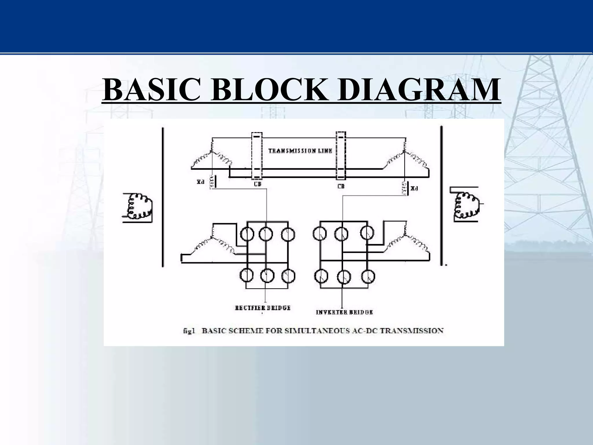
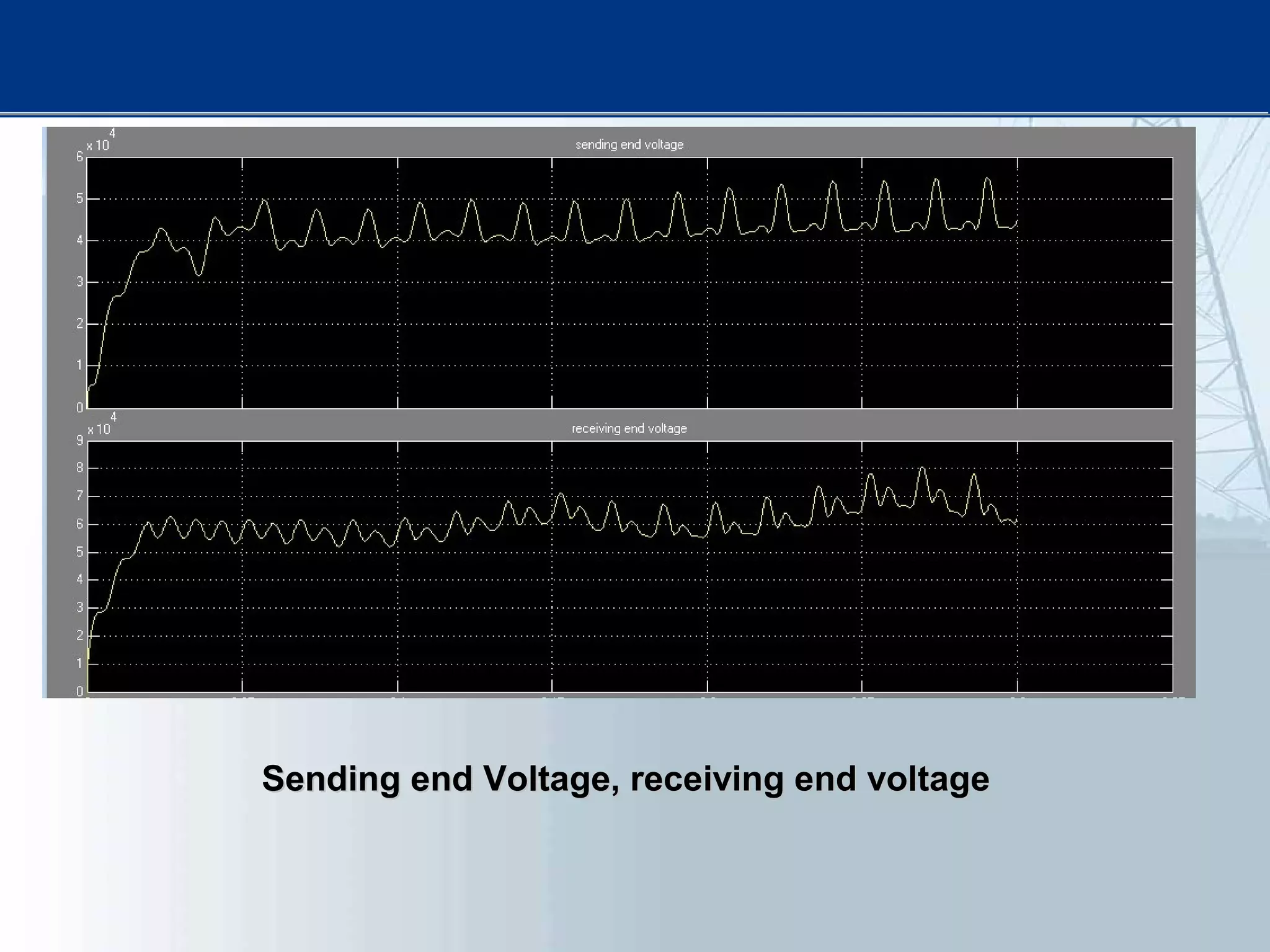
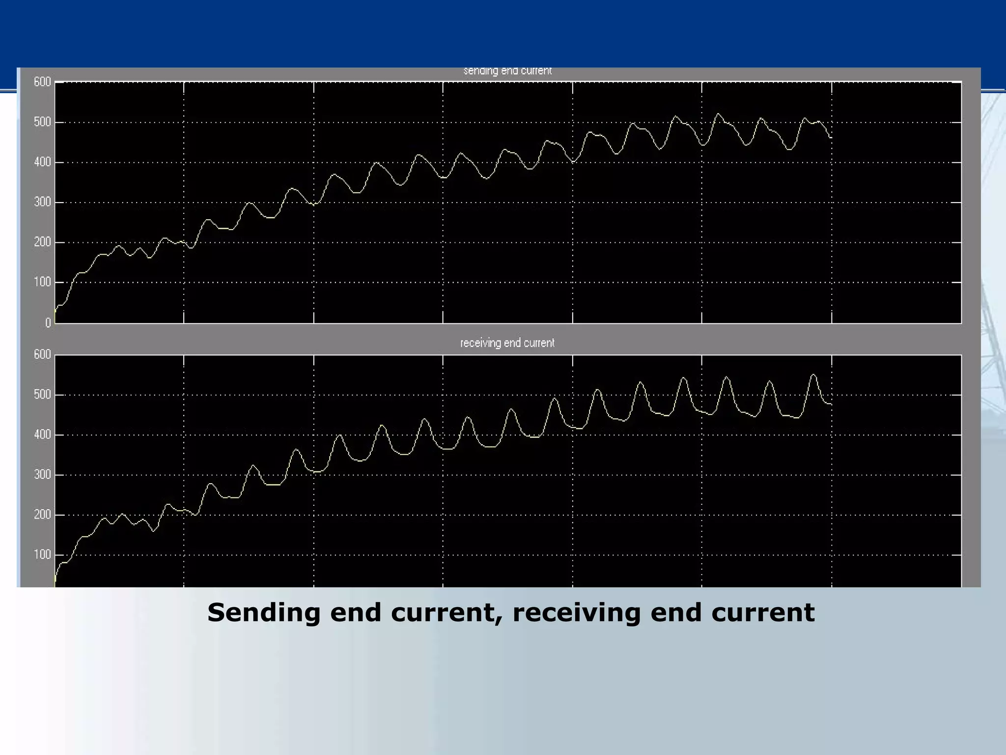
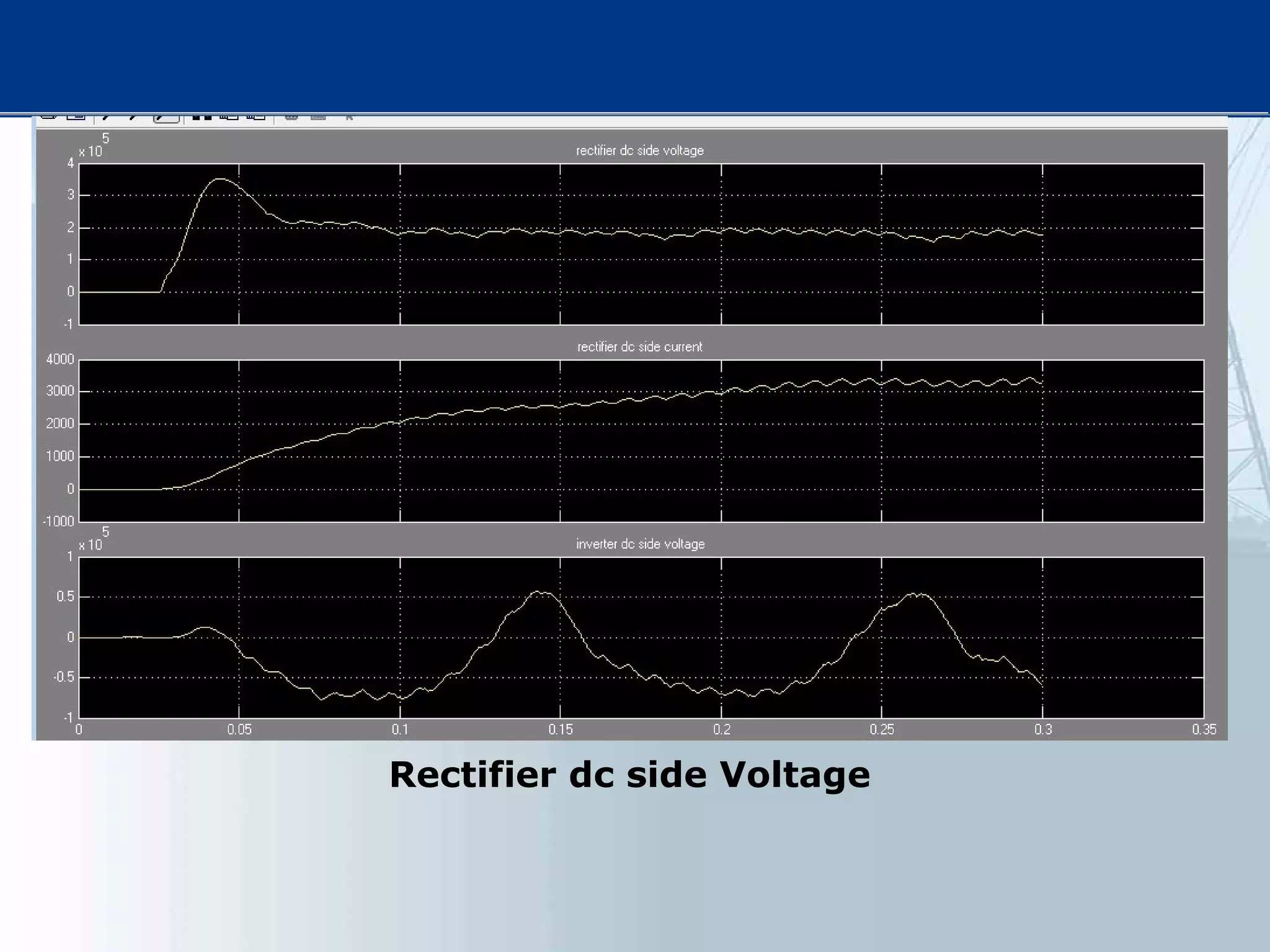
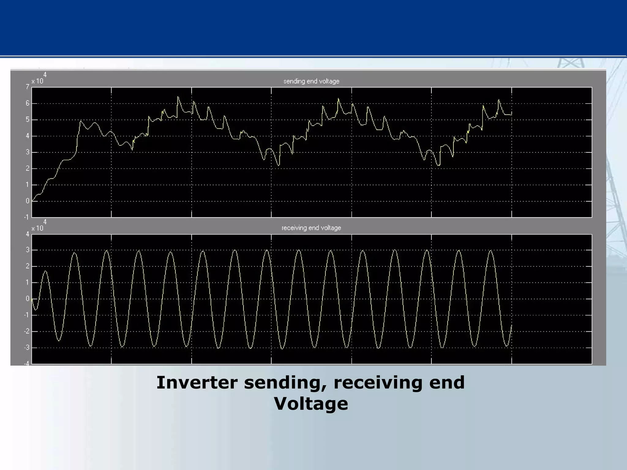
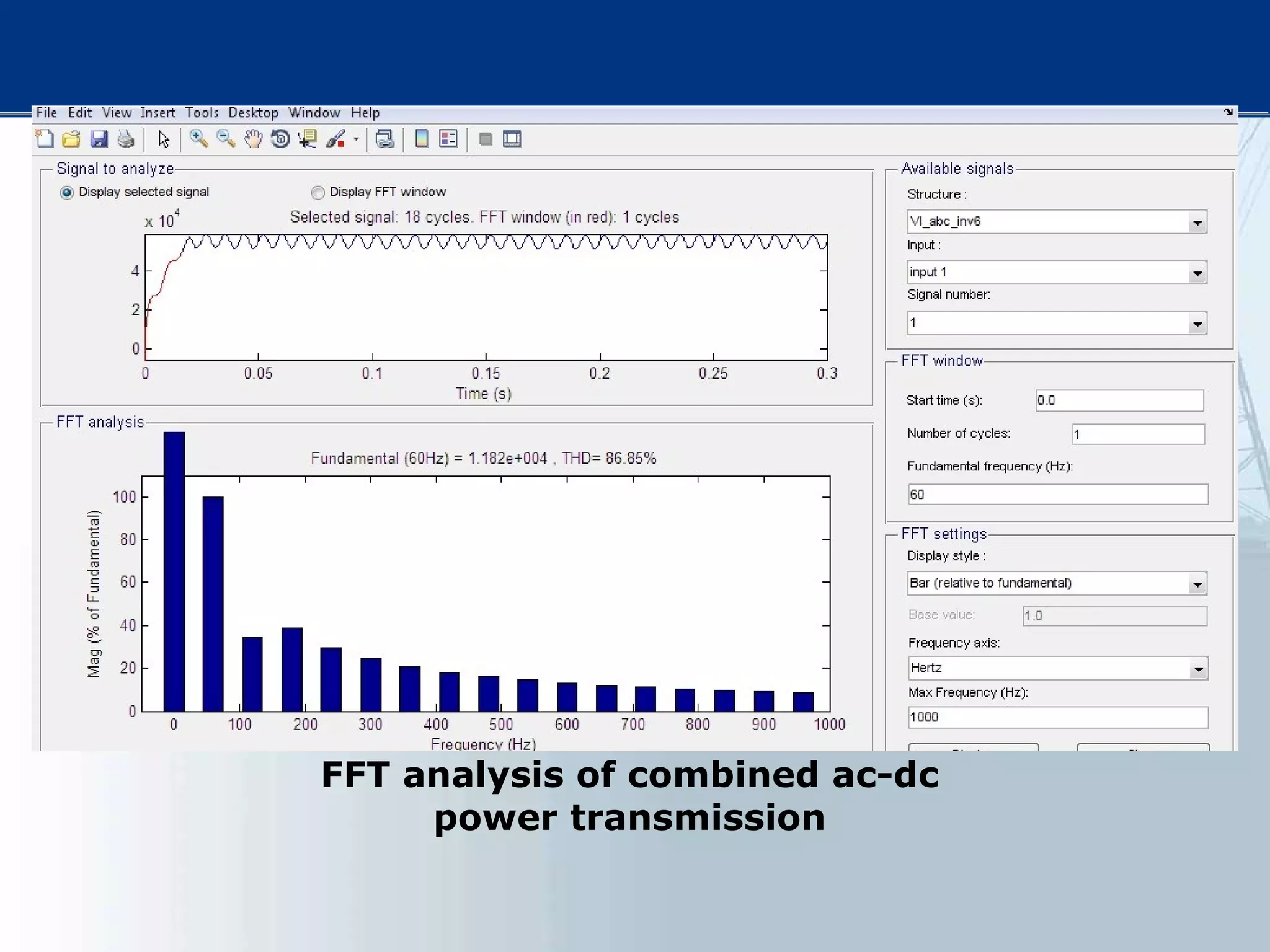
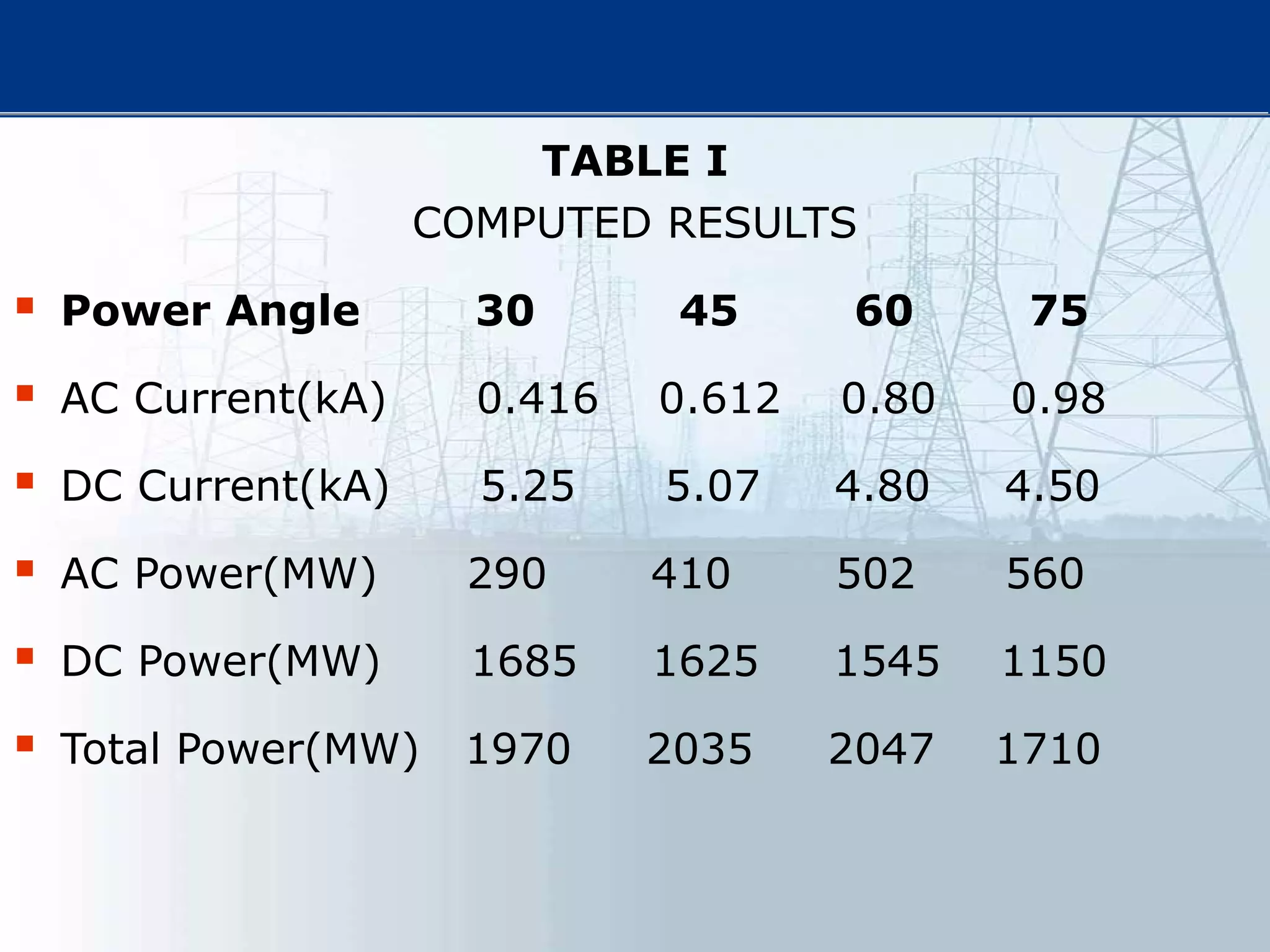
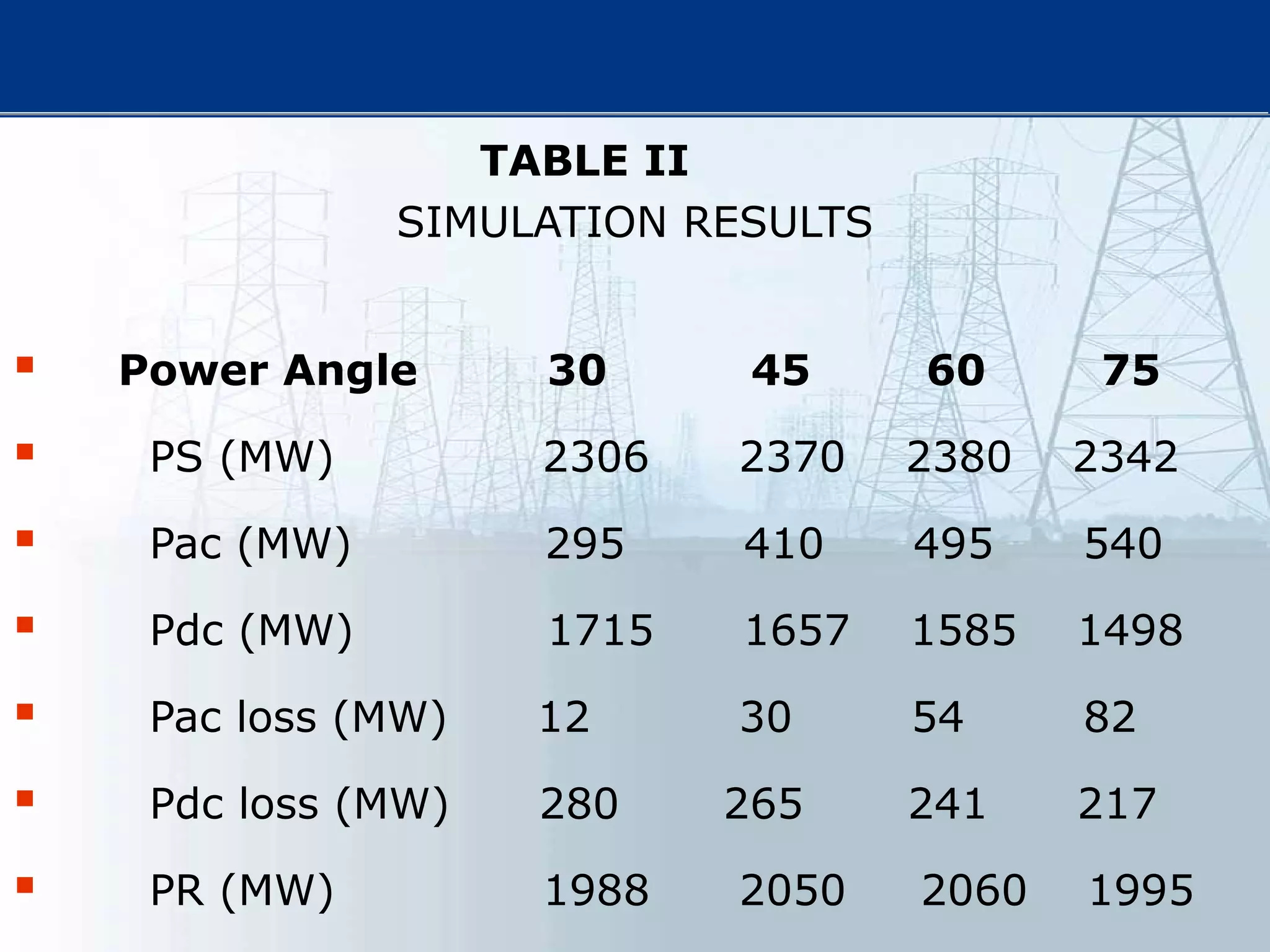
This thesis examines using simultaneous AC-DC power transmission to improve power system stability. Simulation results show stability is enhanced when compared to only AC transmission. The thesis aims to emphasize the advantages of simultaneous transmission for improving stability and damping oscillations. FACTS devices allow flexible control of AC and DC power flows to achieve benefits like better transmission asset utilization and increased grid stability. Results demonstrate substantial gains in power transfer capability and reliability when converting dual AC lines to simultaneous AC-DC transmission.


