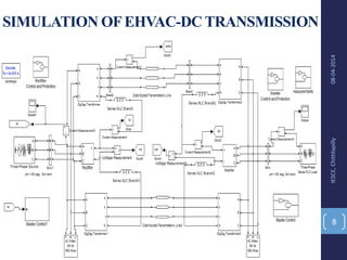
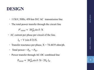
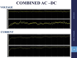
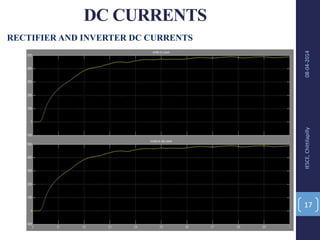
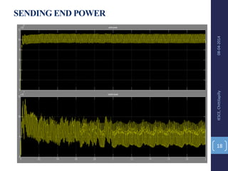
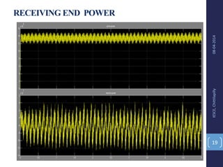
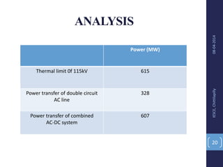
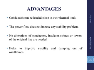
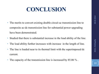
I.E.S COLLEGE OF ENGINEERING
CHITTILAPPILLY, THRISSUR
POWER UPGRADING OF TRANSMISSION LINE
BY COMBINING AC-DC TRANSMISSION
GUIDED BY:
EDISON A.J
ASST.PROFESSOR
EEE DEPT.
IESCE
PRESENTED BY:
GROUP NO. 10
DHANESH K.N (09)
JASIM N.C (17)
MUKHTHAR U.P (34)
SULFATH N.P (52)
VEENA VIVEK (55)
08-04-2014IESCE,Chittilapilly
1
OVERVIEW
• OBJECTIVE
• INTRODUCTION
• SCHEMATIC DIAGRAM
• MATLAB SIMULINK MODELS
• SIMULATION GRAPHS
• ANALYSIS
• ADVANTAGES
• CONCLUSION
• PROJECT REVIEW
• BIBLIOGRAPHY
08-04-2014IESCE,Chittilapilly
2
OBJECTIVE
• Power transfer enhancement , without any alteration in
the existing Extra High Voltage AC line.
• To utilize the advantage of parallel ac–dc transmission
by loading the line close to its upper thermal limit.
08-04-2014IESCE,Chittilapilly
3
INTRODUCTION
• Long extra high voltage (EHV) ac lines cannot be loaded to
their thermal limits in order to keep sufficient margin against
transient instability.
• In simultaneous ac-dc power transmission system, the
conductors are allowed to carry dc current superimposed on
ac current.
• The added power flow does not cause of any transient
instability.
08-04-2014IESCE,Chittilapilly
4
08-04-2014IESCE,Chittilapilly
5
BASIC SCHEME FOR COMPOSITEAC-DC
TRANSMISSION
SIMULATION OFEHV-AC TRANSMISSION
08-04-2014IESCE,Chittilapilly
6
RESULT
08-04-2014IESCE,Chittilapilly
7
SIMULATION OFEHVAC-DC TRANSMISSION
08-04-2014IESCE,Chittilapilly
8
DESIGN
• 115kV, 50Hz, 450 km D/C AC transmission line
• The total power transfer through the circuit line
𝑃′ 𝑡𝑜𝑡𝑎𝑙 ≈ 3𝑉𝑝ℎ
2
sin 𝛿 /X
• AC current per phase per circuit of the line.
𝐼 𝑎 = V (sin 𝛿/2)/X.
• Transfer reactance per phase, X = 74.4435 ohm/ph.
• Total power = 𝑃𝑎𝑐 + 𝑃𝑑𝑐.
• Power transfer through AC-DC combined line
𝑃𝑡𝑜𝑡𝑎𝑙 ≈ 3𝑉𝑝ℎ
2
sin 𝛿 /X+ 2𝑉𝑑 𝐼 𝑑.
08-04-2014IESCE,Chittilapilly
9
MASTERCONTROL
08-04-2014IESCE,Chittilapilly
10
• The Master Control system generates the current reference for both
converters.
• Initiates the starting and stopping of the DC power transmission.
• The protection systems can be switched on and off.
• At the rectifier, the DC fault protection detects a fault on the line and takes
the necessary action to clear the fault.
08-04-2014IESCE,Chittilapilly
11
SIMULATION OF RECTIFIER SIMULATION OF INVERTER
AC FILTER
08-04-2014IESCE,Chittilapilly
12
Reactive power ,
𝑄𝑐 = (𝑉2
/ 𝑋𝑐 )·𝑛2
/((𝑛2
– 1)
Tuned harmonic order,
n= 𝑓𝑛/ 𝑓1.
Quality factor,
Q = n 𝑋 𝐿 /R = 𝑋𝑐 /(n R)
Where, fn – tuning frequency
f1- fundamental frequency
SIMULATION GRAPHS
08-04-2014IESCE,Chittilapilly
13
 AC ALONE:
• AC VOLTAGE: SENDING END, RECEIVING END
• AC CURRENT: SENDING END, RECEIVING END
• SENDING END POWER: ACTIVE, REACTIVE
• RECEIVING END POWER: ACTIVE, REACTIVE
 AC-DC COMBINED:
• VOLTAGE: SENDING END, RECEIVING END
• CURRENT: SENDING END, RECEIVING END
• DC CURRENT: RECTIFIER, INVERTER
• SENDING END POWER: ACTIVE, REACTIVE
• RECEIVING END POWER: ACTIVE, REACTIVE
AC VOLTAGE
08-04-2014IESCE,Chittilapilly
14
AC CURRENT
AC TRANSMISSION
SENDING END POWER
08-04-2014IESCE,Chittilapilly
15
RECEIVING END POWER
ACTIVE
REACTIVE
ACTIVE
REACTIVE
COMBINED AC –DC
08-04-2014IESCE,Chittilapilly
16
VOLTAGE
CURRENT
DC CURRENTS
08-04-2014IESCE,Chittilapilly
17
RECTIFIER AND INVERTER DC CURRENTS
SENDING END POWER
08-04-2014IESCE,Chittilapilly
18
RECEIVING END POWER
08-04-2014IESCE,Chittilapilly
19
ANALYSIS
08-04-2014IESCE,Chittilapilly
20
Power (MW)
Thermal limit 0f 115kV 615
Power transfer of double circuit
AC line
328
Power transfer of combined
AC-DC system
607
ADVANTAGES
• Conductors can be loaded close to their thermal limit.
• The power flow does not impose any stability problem.
• No alterations of conductors, insulator strings or towers
of the original line are needed.
• Helps to improve stability and damping out of
oscillations.
08-04-2014IESCE,Chittilapilly
21
CONCLUSION
• The merits to convert existing double circuit ac transmission line to
composite ac-dc transmission line for substantial power upgrading
have been demonstrated.
• Studied that there is substantial increase in the load ability of the line.
• The load ability further increases with increase in the length of line.
• The line is loaded near to its thermal limit with the superimposed dc
current.
• The capacity of the transmission line is increased by 85.06 % .
08-04-2014IESCE,Chittilapilly
22
PROJECT REVIEW
08-04-2014IESCE,Chittilapilly
23
MONTH STATUS
June 2013 Proposal & finalisation of topic
July 2013 Research for thesis
August 2013 Zeroth Presentation
September 2013 Data collection
October 2013 1st review presentation
December 2013 Simulation of AC started
January 2014 Output obtained
February 2014 Simulation of AC DC started
April 2014 project completed
BIBLIOGRAPHY
• Basu and B. H. Khan-Simultaneous ac-dc power transmission.
• H. Rahman and B. H. Khan, ―Enhanced power transfer by Simultaneous
transmission of AC-DC: a new FACTS concept.
• T.Vijay Muni, T.Vinoditha, D.Kumar Swamy - ―Improvement of Power System
Stability by Simultaneous AC-DC Power Transmission
• N. G. Hingorani, ―FACTS—flexible A.C. transmission system,‖ in Proc. Inst.
Elect. Eng. 5th. Int. Conf. A.C. D.C. Power Trans- mission
• L. K. Gyugyi et al., ―The unified power flow controller; a new approach to
power transmission control,‖ IEEE Trans. Power Del., vol. 10, no. 2, pp. 1085–
1097, Apr. 1995.
• Kundur, Power System Stability and Control. New York: Mc-Graw-Hill, 1994.
08-04-2014IESCE,Chittilapilly
24
08-04-2014IESCE,Chittilapilly
25
THANK YOU

Power upgrading of Transmission Line by Simultaneous AC DC transmission