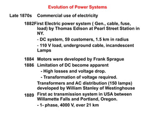
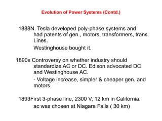
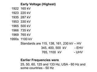
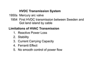
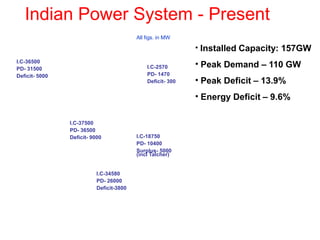
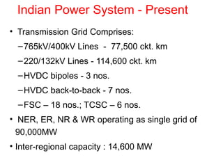
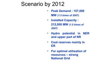
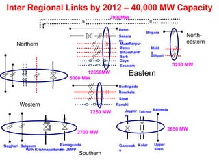
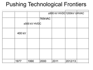
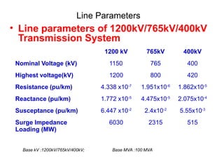
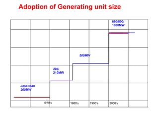
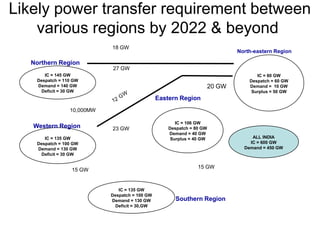
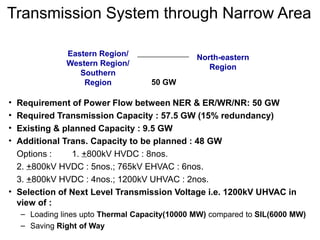
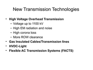
SlideShare a Scribd company logo
Emerging Trends and
Challenges Electric Power
Systems
Evolution of Power Systems
Late 1870s Commercial use of electricity
1882First Electric power system ( Gen., cable, fuse,
load) by Thomas Edison at Pearl Street Station in
NY.
- DC system, 59 customers, 1.5 km in radius
- 110 V load, underground cable, incandescent
Lamps
1884
1886
1889
Motors were developed by Frank Sprague
Limitation of DC become apparent
- High losses and voltage drop.
- Transformation of voltage required.
Transformers and AC distribution (150 lamps)
developed by William Stanley of Westinghouse
First ac transmission system in USA between
Willamette Falls and Portland, Oregon.
- 1- phase, 4000 V, over 21 km
Evolution of Power Systems (Contd.)
1888N. Tesla developed poly-phase systems and
had patents of gen., motors, transformers, trans.
Lines.
Westinghouse bought it.
1890s Controversy on whether industry should
standardize AC or DC. Edison advocated DC
and Westinghouse AC.
- Voltage increase, simpler & cheaper gen. and
motors
1893First 3-phase line, 2300 V, 12 km in California.
ac was chosen at Niagara Falls ( 30 km)
1922
1923
1935
1953
1965
1966
1969
1990s
Early Voltage (Highest)
165 kV
220 kV
287 kV
330 kV
500 kV
735 kV
765 kV
1100 kV
Standards are 115, 138, 161, 230 kV – HV
345, 400, 500 kV - EHV
765, 1100 kV - UHV
Earlier Frequencies were
25, 50, 60, 125 and 133 Hz; USA - 60 Hz and
some countries - 50 Hz
1950s
1954
HVDC Transmission System
Mercury arc valve
First HVDC transmission between Sweden and
Got land island by cable
Limitations of HVAC Transmission
1. Reactive Power Loss
2. Stability
3. Current Carrying Capacity
4. Ferranti Effect
5. No smooth control of power flow
Indian Power System - Present
I.C-37500
PD- 36500
Deficit- 9000
I.C-34580
PD- 26000
Deficit-3800
I.C-18750
PD- 10400
Surplus- 5000
(incl Talcher)
I.C-2570
PD- 1470
Deficit- 300
I.C-36500
PD- 31500
Deficit- 5000
All figs. in MW
• Installed Capacity: 157GW
• Peak Demand – 110 GW
• Peak Deficit – 13.9%
• Energy Deficit – 9.6%
Indian Power System - Present
• Transmission Grid Comprises:
–765kV/400kV Lines - 77,500 ckt. km
–220/132kV Lines - 114,600 ckt. km
–HVDC bipoles - 3 nos.
–HVDC back-to-back - 7 nos.
–FSC – 18 nos.; TCSC – 6 nos.
• NER, ER, NR & WR operating as single grid of
90,000MW
• Inter-regional capacity : 14,600 MW
Inter-regional links – At present
Inter-regional capacity :
14,600MW
Scenario by 2012
• Peak Demand : 157,000
MW (1.5 times of 2007)
• Installed Capacity :
212,000 MW (1.5 times of
2007)
• Hydro potential in NER
and upper part of NR
• Coal reserves mainly in
ER
• For optimal utilisation of
resources – strong
National Grid
Salakat
i
Birpara
Dehri
Sasara
m
Sahupuri
Allahabad North-
eastern
Eastern
Northern
Budhipada
rRourkela
Korba
Raipur
Auraiya
Malanpur
Western
Southern
Balimela
Upper
Sileru
Jeypor
e
Gazuwak
a
Singrauli
Vindhyachal
Talcher
Kolar
Kota
Ujjain
Gorakhpur Muzaffarpur
Balia Patna
BiharshariffBalia
SipatRanchi
Agra
Gwalior
BarhBalia
GayaBalia
Sasaram
RanchiWR Pooling
Zerda
Kankroli
Fatehpur
Agra
NER Pooling
3000MW
5000 MW
12650MW
3250 MW
3650 MW
2700 MW
7250 MW
With Krishnapattanam UMPP
BongaigaonMald
a
BongaigaonSiliguri
Chandrapur
Ramagunda
m
Kolhapur
Nagjhari
Ponda
Belgaum
Inter Regional Links by 2012 – 40,000 MW Capacity
Pushing Technological Frontiers
400 kV
1977 1990 2000 2011 2012/13
765kVAC
±800 kV HVDC1200kV UHVAC
±500 kV HVDC
Line Parameters
• Line parameters of 1200kV/765kV/400kV
Transmission System
1200 kV 765kV 400kV
Nominal Voltage (kV) 1150 765 400
Highest voltage(kV) 1200 800 420
Resistance (pu/km) 4.338 x10⁻⁷
1.951x10⁻⁶
1.862x10⁻⁵
Reactance (pu/km) 1.772 x10⁻⁵
4.475x10⁻⁵
2.075x10⁻⁴
Susceptance (pu/km) 6.447 x10⁻²
2.4x10⁻²
5.55x10⁻³
Surge Impedance
Loading (MW)
6030 2315 515
Base kV :1200kV/765kV/400kV; Base MVA :100 MVA
Adoption of Generating unit size
500MW
200/
210MW
Less than
200MW
1970’s 1980’s 1990’s 2000’s
660/800/
1000MW
Likely power transfer requirement between
various regions by 2022 & beyond
North-eastern Region
Northern Region
27 GW
15 GW
15 GW
10,000MW
18 GW
23 GW
IC = 145 GW
Despatch = 110 GW
Demand = 140 GW
Deficit = 30 GW
Western Region
IC = 135 GW
Despatch = 100 GW
Demand = 130 GW
Deficit = 30 GW
Southern Region
Eastern Region
IC = 106 GW
Despatch = 80 GW
Demand = 40 GW
Surplus = 40 GW
IC = 135 GW
Despatch = 100 GW
Demand = 130 GW
Deficit = 30,GW
IC = 80 GW
Despatch = 60 GW
Demand = 10 GW
Surplus = 50 GW
20 GW
ALL INDIA
IC = 600 GW
Demand = 450 GW
Transmission System through Narrow Area
• Requirement of Power Flow between NER & ER/WR/NR: 50 GW
• Required Transmission Capacity : 57.5 GW (15% redundancy)
• Existing & planned Capacity : 9.5 GW
• Additional Trans. Capacity to be planned : 48 GW
Options : 1. +800kV HVDC : 8nos.
2. +800kV HVDC : 5nos.; 765kV EHVAC : 6nos.
3. +800kV HVDC : 4nos.; 1200kV UHVAC : 2nos.
• Selection of Next Level Transmission Voltage i.e. 1200kV UHVAC in
view of :
– Loading lines upto Thermal Capacity(10000 MW) compared to SIL(6000 MW)
– Saving Right of Way
Eastern Region/
Western Region/
Southern
Region
North-eastern
Region
50 GW
New Transmission Technologies
• High Voltage Overhead Transmission
– Voltage up to 1100 kV
– High EM radiation and noise
– High corona loss
– More ROW clearance
• Gas Insulated Cables/Transmission lines
• HVDC-Light
• Flexible AC Transmission Systems (FACTS)
Gas insulated Transmission Lines
• Benefits of GITL
– Low resistive losses (reduced by factor 4)
– Low capacitive losses and less charging current
– No external electromagnetic fields
– No correction of phase angle is necessary even
for long distance transmission
– No cooling needed
– No danger of fire
– Short repair time
– No aging
– Lower total life cycle costs.
HVDC-Light
• Classical HVDC technology
– Mostly used for long distance point-to-point
transmission
– Requires fast communication channels between two
stations
– Large reactive power support at both stations
– Thyristor valves are used.
– Line or phase commutated converters are used.
• HVDC-Light
– Power transmission through HVDC utilizing voltage
source converters with insulated gate bipolar
transistors (IGBT) which extinguishes the current
more faster and with less energy loss than GTOs.
HVDC-Light
– It is economical even in low power range.
– Real and reactive power is controlled independently in
two HVDC light converters.
– Controls AC voltage rapidly.
– There is possibility to connect passive loads.
– No contribution to short circuit current.
– No need to have fast communication between two
converter stations.
– Operates in all four quadrants.
– PWM scheme is used.
– Opportunity to transmit any amount of current of
power over long distance via cables.
HVDC-Light
– Low complexity-thanks to fewer components
– Small and compact
– Useful in windmills
– Offers asynchronous operation.
• First HVDC-Light pilot transmission for 3 MW, ±10kV
in March, 1997 (Sweden)
• First commercial project 50 MW, 70 kV, 72 km, in
1999.
• Transmission system limitations:
– System Stability
• Transient stability
• Voltage stability
• Dynamic Stability
• Steady state stability
• Frequency collapse
• Sub-synchronous resonance
– Loop flows
– Voltage limits
– Thermal limits of lines
– High short-circuit limits
FLEXIBLE AC TRANSMISSION SYSTEM (FACTS)
• Flexible AC Transmission Systems (FACTS) are
the name given to the application of power
electronics devices to control the power flows
and other quantities in power systems.
• Benefits of FACTS Technology
– To increase the power transfer capability of
transmission networks and
– To provide direct control of power flow over
designated transmission routes.
• However it offers following opportunities
– Control of power flow as ordered so that it follows on
the prescribed transmission corridors.
– The use of control of the power flow may be to follow
a contract, meet the utilities’ own needs, ensure
optimum power flow, ride through emergency
conditions, or a combination thereof.
– Increase the loading capability of lines to their thermal
capabilities, including short-term and seasonal.
– Increase the system security through raising the
transient stability limit, limiting short-circuit currents
and overloads, managing cascading blackouts and
damping electromechanical oscillations of power
systems and machines.
– Provide secure tie line connections to neighboring
utilities and regions thereby decreasing overall
generation reserve requirements on both sides.
– Allow secure loading of transmission line to a level
closer to the thermal limits, while avoiding overloading
and reduce the generation margin by having the
ability to transfer more power between the controlled
areas.
– Damping of power oscillation,
– Preventing cascading outages by limiting the impacts
of faults and equipment failures.
– Provide greater flexibility in sitting new generation.
– Upgrade of lines.
– Reduce reactive power flows, thus allowing the lines
to carry more active power.
– Reduce loop flows.
– Increase utilization of lowest cost generation.
• Whether HVDC or FACTS ?
– Both are complementary technologies.
– The role of HVDC is to interconnect ac systems where
a reliable ac interconnection would be too expensive.
• Independent frequency and control
• Lower line cost
• Power control, voltage control and stability control
possible.
– The large market potential for FACTS is within AC
system on a value added basis where
• The existing steady-state phase angle between bus nodes
is reasonable.
• The cost of FACTS solution is lower than the HVDC cost
and
• The required FACTS controller capacity is lesser than the
transmission rating.
• FACTS technology is concerned with
development of following two areas
– High rating Power electronic switching devices and
Pulse Width Modulated converters.
– Control methods using digital signal processing and
Microprocessors.
– Devices: IGBT Insulated gate bipolar transistors,
GTO gate turn off thyristor, MCT Metal oxide
thyristor (MOS) controlled transistor
Throughput HVDC 2 terminal FACTS
200 MW $ 40-50 M $ 5-10 M
500 MW 75-100 M 10-20 M
1000 MW 120-170 M 20-30 M
2000 MW 200-300 M 30-50 M
Table: Comparison of power semiconductor devices
Thyris-
tor
GTO IGBT SI *
thyristor
MCT MOSFET
Max. voltage rating (V) 8000 6000 1700 2500 3000 1000
Max. current rating (A) 4000 6000 800 800 400 100
Voltage blocking Sym./
Asym.
Sym./
Asym.
Asym. Asym. Sym./
Asym
Asym.
Gating Pulse Current Voltage Current Voltage Voltage
Conduction drop (V) 1.2 2.5 3 4 1.2 Resistive
Switching frequency
(kHz)
1 5 20 20 20 100
Development target
max. voltage rating (kV)
10 10 3.5 5 5 2
Development target
max. current rating (kA)
8 8 2 2 2 0.2
* SI: Static induction thyristor, MOSFET: MOS field effect transistor
• Developments in Generation side
– Powerformer Energy System
–Distributed Generations
•Wind Power
• Fuel Cells
•Biomass etc.
–Combined Cycle Power Plants
Powerformer Energy System
PowerformerTM
Benefits
• Higher performance (availability, overload)
• Environmental improvement
• Lower weight
• Less total space requirement
• Lower cost for Civil Works
• Less maintenance
• Reduced losses
• Lower investment
• Lower LCC
E(kV/mm)
3kV/mm
6-9kV/mm
E-field
non-uniform
E-field
uniform
Bar Cable
Electrical Field Distribution
Stator winding
Conductor (1), Inner semi-conducting layer (2),
Insulation (3) and an outer semi-conducting layer (4).
Opportunities/Challenges
• Fault Analysis including Internal Fault
• Faulty Synchronization
• Model for Double Winding Generator
DG includes the application of small generations in
the range of 15 to 10,000 kW, scattered
throughout a power system
DG includes all use of small electric power
generators whether located on the utility system at
the site of a utility customer, or at an isolated
site not connected to the power grid.
By contrast, dispersed generation (capacity
ranges from 10 to 250 kW), a subset of distributed
generation, refers to generation that is located at
customer facilities or off the utility system.
Distributed Generation/Dispersed Generation
DG includes traditional -- diesel, combustion
turbine, combined cycle turbine, low-head hydro,
or other rotating machinery and renewable -- wind,
solar, or low-head hydro generation.
The plant efficiency of most existing large central
generation units is in the range of 28 to 35%,
converting between 28 to 35% of the energy in their
fuel into useful electric power.
By contrast, efficiencies of 40 to 55% are attributed
to small fuel cells and to various hi-tech gas turbine
and combined cycle units suitable for DG
application.
Part of this comparison is unfair. Modern DG utilize
prefect hi-tech materials and incorporating advanced
designs that minimize wear and required maintenance
and include extensive computerized control that
reduces operating labor.
DG “Wins” Not Because It is Efficient, But
Because It Avoids T&D Costs
Proximity is often more important than efficiency
Why use DG units, if they are not most efficient or the
lowest cost?
The reason is that they are closer to the customer. They
only have to be more economical than the central station
generation and its associated T&D system. A T&D system
represents a significant cost in initial capital and
continuing O&M.
By avoiding T&D costs and those reliability problems, DG
can provide better service at lower cost, at least in some
cases. For example, in situations where an existing
distribution system is near capacity, so that it must be
reinforced in order to serve new or additional electrical
demand, the capital cost/kW for T&D expansion alone can
exceed that for DG units.
Operational Changes
Intelligent Grid - WAMS
• Power System Restructuring
(Privatization or Deregulation)
– But not only Privatization
• Deregulation is also known as
– Competitive power market
– Re-regulated market
– Open Power Market
– Vertically unbundled power system
– Open access
Transmission
Business
Distribution
Business
Generation
Business
Vertical
separation
Horizontal separation
or Vertical cut
Horizontal separation
or Vertical cut
• Why Restructuring of Electric Supply
Industries?
– Better experience of other restructured market
such as communication, banking, oil and gas,
airlines, etc.
– Competition among energy suppliers and
wide choice for electric customers.
• Why was the electric utility industry
regulated?
– Regulation originally reduced risk, as it was
perceived by both business and government.
– Several important benefits:
• It legitimized the electric utility business.
• It gave utilities recognition and limited support
from the local Govt. in approving ROW and
easements.
• It assured a return on the investment, regulated as
that might be.
• It established a local monopoly in building the
system and quality of supply without competitors.
• Simplified buying process for consumers.
• Electricity of new and confusing to deal with the
conflicting claims, standards and offerings of
different power companies.
• Least cost operation.
• Meeting social obligations
• Hugh investments with high risk
• Forces behind the Restructuring are
– High tariffs and over staffing
– Global economic crisis
– Regulatory failure
– Political and ideological changes
– Managerial inefficiency
– Lack of public resources for the future
development
– Technological advancement
– Rise of environmentalism
– Pressure of Financial institutions
– Rise in public awareness
– Some more …….
•
Reasons why deregulation is appealing
No longer necessary The primary reason for regulation,
to foster the development of ESI
infrastructure, had been achieved.
Electricity Price may drop Expected to drop due to innovation
and competition.
Customer focus will improve Expected to result in wider
customer choice and more attention
to improve service
Encourage innovation Rewards to risk takers and
encourage new technology and
business approaches,
Augments privatization In the countries where Govt. wishes
to sell state -owned utilities,
deregulation may provide potential
buyers and new producers.
• What will be the transformation ?
– Vertically integrated => vertically unbundled
– Regulated cost-based ==> Unregulated price-
based
– Monopoly ==> Competition
– service ==> commodity
– consumer ==> customer
– privilege ==> choice
– Engineers  Lawyer/Manager
• A number of questions to be answered
– Is a Restructuring good for our society?
– What are the key issues in moving towards the
restructuring ?
– What are the implications for current industry
participants?
– What type of new participants will be seen and
why ?
– What should be structure of market and
operation?
– What might an electricity transaction of future
look like?
• What will be the Potential Problems ?
– Congestion and Market power
– Obligation to serve
– Some suppliers at disadvantages
– Price volatility
– Non-performance obligation
– Loss operating flexibility
– Pricing of energy and transmission services
– ATC calculations
– Ancillary services Management
• Reserves
• Black start capability
• Voltage and frequency control
• System security and stability
• Transmission reserves
– Market Settlements and disputes
Milestones of Restructuring
- 1982 Chile
- 1990 UK
- 1992 Argentina, Sweden & Norway
- 1993 Bolivia & Colombia
- 1994 Australia
- 1996 New Zeeland
- 1997 Panama, El Salvador, Guatemala,
Nicaragua, Costa Rica and Honduras
- 1998 California, USA and several others.
- 2000 Several EU and American States
• Markets are defined by the commodity traded
– Energy
– Transmission system
– Ancillary services
• Markets defined by the time-frame of trade
– Day-ahead
– Hour-ahead
– Real-time
• Based on auction - single-sided or double sided
• Based on type of bids --> block or linear bid
• Based on generation settlement - uniform price
(MCP) or pay-as-bid
Market Clearing Price
Gen. Price
($)
MW
Gen-1 2.5 20
Gen-2 2.0 10
Gen-3 2.4 15
Gen-4 2.3 45
Gen-5 2.2 30
Gen-2
Gen-5
Gen-4
Gen-3
Gen-1
Demand = 80 MW
O MW
1O MW
40 MW
85 MW
• Electricity Market is very risky
– Electricity is not storable in bulk quantity
– End user demand is typically constant
– Trading is directly related to the reliability of the grid
– Demand and supply should be exact
– Electricity prices are directly related with other
volatile market participants.
– Cost of continuity is more than cost of electric.
Thank You

More Related Content

What's hot

Hvdc transmission
Hvdc transmissionHvdc transmission
Hvdc transmission
Tashfain Yousuf
 
Hvdc system.pptx
Hvdc system.pptxHvdc system.pptx
Hvdc system.pptx
Ashfaque Yoosuf
 
Conventional and emerging converter technologies in hvdc power transmission s...
Conventional and emerging converter technologies in hvdc power transmission s...Conventional and emerging converter technologies in hvdc power transmission s...
Conventional and emerging converter technologies in hvdc power transmission s...
Naveed Shahzad
 
Group 8 hvdc
Group  8 hvdcGroup  8 hvdc
Group 8 hvdc
Mahesh B
 
Hvdc
HvdcHvdc
Hvdc transmission & its applications
Hvdc transmission & its applicationsHvdc transmission & its applications
Hvdc transmission & its applications
Pooja Dubey
 
Principles Control & Protection of HVDC Schemes
Principles Control & Protection of HVDC SchemesPrinciples Control & Protection of HVDC Schemes
Principles Control & Protection of HVDC Schemes
Power System Operation
 
Hvdc transmission seminar
Hvdc transmission seminar Hvdc transmission seminar
Hvdc transmission seminar
Utkarsh Jambhule
 
Structure of Transmission System in India
Structure of Transmission System in IndiaStructure of Transmission System in India
Structure of Transmission System in India
Himanshu Pathak
 
FAULT ANALYSIS IN HVDC & HVAC TRANSMISSION LINE
FAULT ANALYSIS IN HVDC & HVAC TRANSMISSION LINEFAULT ANALYSIS IN HVDC & HVAC TRANSMISSION LINE
FAULT ANALYSIS IN HVDC & HVAC TRANSMISSION LINE
Dr. Babasaheb Ambedkar Technological University
 
Neil Kirby: VSC HVDC Transmission and Emerging Technologies in DC Grids
Neil Kirby: VSC HVDC Transmission and Emerging Technologies in DC GridsNeil Kirby: VSC HVDC Transmission and Emerging Technologies in DC Grids
Neil Kirby: VSC HVDC Transmission and Emerging Technologies in DC Grids
EnergyTech2015
 
Hvdc ppt with animated videos
Hvdc ppt with animated videosHvdc ppt with animated videos
Hvdc ppt with animated videos
Jawad Ali
 
Power System with VSC-HVDC Interconnection
Power System with VSC-HVDC InterconnectionPower System with VSC-HVDC Interconnection
Power System with VSC-HVDC Interconnection
Bérengère VIGNAUX
 
Power Transmission & Distribution in India
Power Transmission & Distribution in IndiaPower Transmission & Distribution in India
Power Transmission & Distribution in India
Indian Energy Sector
 
Hvdc transmission by pankaj chaudhary
Hvdc transmission by pankaj chaudharyHvdc transmission by pankaj chaudhary
Hvdc transmission by pankaj chaudhary
PANKAJRANJANA143
 
Hvdc notes
Hvdc notesHvdc notes
Hvdc notes
mahesh babu
 
MTDC SYSTEMS
MTDC SYSTEMSMTDC SYSTEMS
MTDC SYSTEMS
Prashant Kumar
 
800kv multiterminal system in india
800kv multiterminal system in india800kv multiterminal system in india
800kv multiterminal system in india
alpna1808
 
Simulation and analysis of HVDC on MATLAB and PSCAD
Simulation and analysis of HVDC on MATLAB and PSCADSimulation and analysis of HVDC on MATLAB and PSCAD
Simulation and analysis of HVDC on MATLAB and PSCAD
Vishal Bhimani
 
Power upgrading of transmission line by combining ac dc transmission
Power upgrading of transmission line by combining ac dc transmissionPower upgrading of transmission line by combining ac dc transmission
Power upgrading of transmission line by combining ac dc transmission
Shailesh Senta
 

What's hot (20)

Hvdc transmission
Hvdc transmissionHvdc transmission
Hvdc transmission
 
Hvdc system.pptx
Hvdc system.pptxHvdc system.pptx
Hvdc system.pptx
 
Conventional and emerging converter technologies in hvdc power transmission s...
Conventional and emerging converter technologies in hvdc power transmission s...Conventional and emerging converter technologies in hvdc power transmission s...
Conventional and emerging converter technologies in hvdc power transmission s...
 
Group 8 hvdc
Group  8 hvdcGroup  8 hvdc
Group 8 hvdc
 
Hvdc
HvdcHvdc
Hvdc
 
Hvdc transmission & its applications
Hvdc transmission & its applicationsHvdc transmission & its applications
Hvdc transmission & its applications
 
Principles Control & Protection of HVDC Schemes
Principles Control & Protection of HVDC SchemesPrinciples Control & Protection of HVDC Schemes
Principles Control & Protection of HVDC Schemes
 
Hvdc transmission seminar
Hvdc transmission seminar Hvdc transmission seminar
Hvdc transmission seminar
 
Structure of Transmission System in India
Structure of Transmission System in IndiaStructure of Transmission System in India
Structure of Transmission System in India
 
FAULT ANALYSIS IN HVDC & HVAC TRANSMISSION LINE
FAULT ANALYSIS IN HVDC & HVAC TRANSMISSION LINEFAULT ANALYSIS IN HVDC & HVAC TRANSMISSION LINE
FAULT ANALYSIS IN HVDC & HVAC TRANSMISSION LINE
 
Neil Kirby: VSC HVDC Transmission and Emerging Technologies in DC Grids
Neil Kirby: VSC HVDC Transmission and Emerging Technologies in DC GridsNeil Kirby: VSC HVDC Transmission and Emerging Technologies in DC Grids
Neil Kirby: VSC HVDC Transmission and Emerging Technologies in DC Grids
 
Hvdc ppt with animated videos
Hvdc ppt with animated videosHvdc ppt with animated videos
Hvdc ppt with animated videos
 
Power System with VSC-HVDC Interconnection
Power System with VSC-HVDC InterconnectionPower System with VSC-HVDC Interconnection
Power System with VSC-HVDC Interconnection
 
Power Transmission & Distribution in India
Power Transmission & Distribution in IndiaPower Transmission & Distribution in India
Power Transmission & Distribution in India
 
Hvdc transmission by pankaj chaudhary
Hvdc transmission by pankaj chaudharyHvdc transmission by pankaj chaudhary
Hvdc transmission by pankaj chaudhary
 
Hvdc notes
Hvdc notesHvdc notes
Hvdc notes
 
MTDC SYSTEMS
MTDC SYSTEMSMTDC SYSTEMS
MTDC SYSTEMS
 
800kv multiterminal system in india
800kv multiterminal system in india800kv multiterminal system in india
800kv multiterminal system in india
 
Simulation and analysis of HVDC on MATLAB and PSCAD
Simulation and analysis of HVDC on MATLAB and PSCADSimulation and analysis of HVDC on MATLAB and PSCAD
Simulation and analysis of HVDC on MATLAB and PSCAD
 
Power upgrading of transmission line by combining ac dc transmission
Power upgrading of transmission line by combining ac dc transmissionPower upgrading of transmission line by combining ac dc transmission
Power upgrading of transmission line by combining ac dc transmission
 

Viewers also liked

Instrumentation
InstrumentationInstrumentation
Instrumentation
mkanth
 
1200 kv ultra high voltage transmission system by prannaya kumar giri & b...
1200 kv  ultra high voltage transmission system  by   prannaya kumar giri & b...1200 kv  ultra high voltage transmission system  by   prannaya kumar giri & b...
1200 kv ultra high voltage transmission system by prannaya kumar giri & b...
Prannay Kumar Giri
 
Ushering in a new era in power transmission
Ushering in a new era in power transmissionUshering in a new era in power transmission
Ushering in a new era in power transmission
Pavan Kumar
 
ABT a complete report and a case study
ABT a complete report and a case studyABT a complete report and a case study
ABT a complete report and a case study
Waseem Hashmat
 
smart Grid
smart Gridsmart Grid
smart Grid
mkanth
 
Project
ProjectProject
Project
mkanth
 
Nano mercury power generation
Nano mercury power generationNano mercury power generation
Nano mercury power generation
mkanth
 
Survey & ts for ehv lines
Survey & ts for ehv linesSurvey & ts for ehv lines
Survey & ts for ehv lines
Mahesh Sontyal
 
ABT (Availability Based Tariff) - UI (Unscheduled Interchange)
ABT (Availability Based Tariff) - UI (Unscheduled Interchange)ABT (Availability Based Tariff) - UI (Unscheduled Interchange)
ABT (Availability Based Tariff) - UI (Unscheduled Interchange)
shyamies11
 
Availability based tariff
Availability based tariffAvailability based tariff
Availability based tariff
Power grid corporation of india limited
 
Inductorless DC-AC Cascaded H-bridge Multilevel Boost Inverter for Electric/...
Inductorless DC-AC Cascaded H-bridge MultilevelBoost Inverter for Electric/...Inductorless DC-AC Cascaded H-bridge MultilevelBoost Inverter for Electric/...
Inductorless DC-AC Cascaded H-bridge Multilevel Boost Inverter for Electric/...
mkanth
 
Transmisiion line design concept
Transmisiion line design conceptTransmisiion line design concept
Transmisiion line design concept
Kumar VEL
 
Presentation on Smart Grid
Presentation on Smart GridPresentation on Smart Grid
Presentation on Smart Grid
nickitran
 
SMART GRID DEVELOPMENT IN INDIA - by Mr. S.R. Sethi, Senior Advisor UPES
SMART GRID DEVELOPMENT IN INDIA - by Mr. S.R. Sethi, Senior Advisor UPES SMART GRID DEVELOPMENT IN INDIA - by Mr. S.R. Sethi, Senior Advisor UPES
SMART GRID DEVELOPMENT IN INDIA - by Mr. S.R. Sethi, Senior Advisor UPES
UPES Dehradun
 
THERMAL POWER STATION PPT.
THERMAL POWER STATION PPT.THERMAL POWER STATION PPT.
THERMAL POWER STATION PPT.
Anish Anand
 
Smart grid presentation
Smart grid presentationSmart grid presentation
Smart grid presentation
Norrazman Zaiha Zainol
 
ppt on Smart Grid
ppt on Smart Gridppt on Smart Grid
ppt on Smart Grid
agr_vandana30
 
Construction EHV Transmission Line
Construction EHV Transmission LineConstruction EHV Transmission Line
Construction EHV Transmission Line
SURESH GOPAL
 
Electrical transmission line
Electrical transmission lineElectrical transmission line
Electrical transmission line
Dhananjay Jha
 
A Novel Approach for Fault Location of Overhead Transmission Line With Noncon...
A Novel Approach for Fault Location of Overhead Transmission Line With Noncon...A Novel Approach for Fault Location of Overhead Transmission Line With Noncon...
A Novel Approach for Fault Location of Overhead Transmission Line With Noncon...
Nidheesh Namboodhiri
 

Viewers also liked (20)

Instrumentation
InstrumentationInstrumentation
Instrumentation
 
1200 kv ultra high voltage transmission system by prannaya kumar giri & b...
1200 kv  ultra high voltage transmission system  by   prannaya kumar giri & b...1200 kv  ultra high voltage transmission system  by   prannaya kumar giri & b...
1200 kv ultra high voltage transmission system by prannaya kumar giri & b...
 
Ushering in a new era in power transmission
Ushering in a new era in power transmissionUshering in a new era in power transmission
Ushering in a new era in power transmission
 
ABT a complete report and a case study
ABT a complete report and a case studyABT a complete report and a case study
ABT a complete report and a case study
 
smart Grid
smart Gridsmart Grid
smart Grid
 
Project
ProjectProject
Project
 
Nano mercury power generation
Nano mercury power generationNano mercury power generation
Nano mercury power generation
 
Survey & ts for ehv lines
Survey & ts for ehv linesSurvey & ts for ehv lines
Survey & ts for ehv lines
 
ABT (Availability Based Tariff) - UI (Unscheduled Interchange)
ABT (Availability Based Tariff) - UI (Unscheduled Interchange)ABT (Availability Based Tariff) - UI (Unscheduled Interchange)
ABT (Availability Based Tariff) - UI (Unscheduled Interchange)
 
Availability based tariff
Availability based tariffAvailability based tariff
Availability based tariff
 
Inductorless DC-AC Cascaded H-bridge Multilevel Boost Inverter for Electric/...
Inductorless DC-AC Cascaded H-bridge MultilevelBoost Inverter for Electric/...Inductorless DC-AC Cascaded H-bridge MultilevelBoost Inverter for Electric/...
Inductorless DC-AC Cascaded H-bridge Multilevel Boost Inverter for Electric/...
 
Transmisiion line design concept
Transmisiion line design conceptTransmisiion line design concept
Transmisiion line design concept
 
Presentation on Smart Grid
Presentation on Smart GridPresentation on Smart Grid
Presentation on Smart Grid
 
SMART GRID DEVELOPMENT IN INDIA - by Mr. S.R. Sethi, Senior Advisor UPES
SMART GRID DEVELOPMENT IN INDIA - by Mr. S.R. Sethi, Senior Advisor UPES SMART GRID DEVELOPMENT IN INDIA - by Mr. S.R. Sethi, Senior Advisor UPES
SMART GRID DEVELOPMENT IN INDIA - by Mr. S.R. Sethi, Senior Advisor UPES
 
THERMAL POWER STATION PPT.
THERMAL POWER STATION PPT.THERMAL POWER STATION PPT.
THERMAL POWER STATION PPT.
 
Smart grid presentation
Smart grid presentationSmart grid presentation
Smart grid presentation
 
ppt on Smart Grid
ppt on Smart Gridppt on Smart Grid
ppt on Smart Grid
 
Construction EHV Transmission Line
Construction EHV Transmission LineConstruction EHV Transmission Line
Construction EHV Transmission Line
 
Electrical transmission line
Electrical transmission lineElectrical transmission line
Electrical transmission line
 
A Novel Approach for Fault Location of Overhead Transmission Line With Noncon...
A Novel Approach for Fault Location of Overhead Transmission Line With Noncon...A Novel Approach for Fault Location of Overhead Transmission Line With Noncon...
A Novel Approach for Fault Location of Overhead Transmission Line With Noncon...
 

Similar to Emergingtrends

Chaper 4 Unit 1 Basics of HVDC Transmission.ppt
Chaper 4 Unit 1 Basics of HVDC Transmission.pptChaper 4 Unit 1 Basics of HVDC Transmission.ppt
Chaper 4 Unit 1 Basics of HVDC Transmission.ppt
onlystu007
 
Status of hvdc links
Status of hvdc linksStatus of hvdc links
Status of hvdc links
abhishek pratap singh
 
transmission&distribution.ppt
transmission&distribution.ppttransmission&distribution.ppt
transmission&distribution.ppt
sasitharjaisankaran1
 
ELECTRICAL POWER TRANSMISSION-3.pptx
ELECTRICAL POWER TRANSMISSION-3.pptxELECTRICAL POWER TRANSMISSION-3.pptx
ELECTRICAL POWER TRANSMISSION-3.pptx
amitpandey509058
 
introduction to high voltage engineering.pdf
introduction to high voltage engineering.pdfintroduction to high voltage engineering.pdf
introduction to high voltage engineering.pdf
HASNAINNAZIR1
 
Hvdc dad
Hvdc dadHvdc dad
Hvdc dad
dharmesh dabhi
 
HVDC Transimmison Systems
HVDC Transimmison SystemsHVDC Transimmison Systems
Edited hvdc2222upload
Edited hvdc2222uploadEdited hvdc2222upload
Edited hvdc2222upload
Mayuresh Vichare
 
industrial-training-at-howrah-220-kv-substation.pptx
industrial-training-at-howrah-220-kv-substation.pptxindustrial-training-at-howrah-220-kv-substation.pptx
industrial-training-at-howrah-220-kv-substation.pptx
ShubhoDas5
 
HVDC and FACTS for Improved Power Delivery Through Long Transmission Lines
HVDC and FACTS for Improved Power Delivery Through Long Transmission LinesHVDC and FACTS for Improved Power Delivery Through Long Transmission Lines
HVDC and FACTS for Improved Power Delivery Through Long Transmission Lines
Rajaram Meena
 
RAJARAM PPT
RAJARAM PPTRAJARAM PPT
RAJARAM PPT
Rajaram Meena
 
POWER SYSTEMS – II chapter 1 transmission line modelling.pptx
POWER SYSTEMS – II chapter 1 transmission line modelling.pptxPOWER SYSTEMS – II chapter 1 transmission line modelling.pptx
POWER SYSTEMS – II chapter 1 transmission line modelling.pptx
MaipaliJyoshnaDevi
 
introduction to power system
introduction to power systemintroduction to power system
introduction to power system
Natnael Addisu
 
An overview of FACTS devices
An overview of FACTS devicesAn overview of FACTS devices
An overview of FACTS devices
Indian Institute of Technology Guwahati
 
HVDC vs HVAC ppt
HVDC vs HVAC pptHVDC vs HVAC ppt
HVDC vs HVAC ppt
Sameer Gupta
 
HVDC presentation
HVDC presentationHVDC presentation
HVDC presentation
sagnikroychowdhury
 
High Voltage Direct Current(Hvdc) transmission
High Voltage Direct Current(Hvdc) transmissionHigh Voltage Direct Current(Hvdc) transmission
High Voltage Direct Current(Hvdc) transmission
University of Gujrat, Pakistan
 
High Voltage DC Transmission
High Voltage DC TransmissionHigh Voltage DC Transmission
High Voltage DC Transmission
krishna koundinya
 
High Voltage Dc (HVDC) transmission
High Voltage Dc (HVDC) transmissionHigh Voltage Dc (HVDC) transmission
High Voltage Dc (HVDC) transmission
ZunAib Ali
 
Industrial Training at Howrah 220 kV Substation.
Industrial Training at Howrah 220 kV Substation.Industrial Training at Howrah 220 kV Substation.
Industrial Training at Howrah 220 kV Substation.
Avirup Ghosh
 

Similar to Emergingtrends (20)

Chaper 4 Unit 1 Basics of HVDC Transmission.ppt
Chaper 4 Unit 1 Basics of HVDC Transmission.pptChaper 4 Unit 1 Basics of HVDC Transmission.ppt
Chaper 4 Unit 1 Basics of HVDC Transmission.ppt
 
Status of hvdc links
Status of hvdc linksStatus of hvdc links
Status of hvdc links
 
transmission&distribution.ppt
transmission&distribution.ppttransmission&distribution.ppt
transmission&distribution.ppt
 
ELECTRICAL POWER TRANSMISSION-3.pptx
ELECTRICAL POWER TRANSMISSION-3.pptxELECTRICAL POWER TRANSMISSION-3.pptx
ELECTRICAL POWER TRANSMISSION-3.pptx
 
introduction to high voltage engineering.pdf
introduction to high voltage engineering.pdfintroduction to high voltage engineering.pdf
introduction to high voltage engineering.pdf
 
Hvdc dad
Hvdc dadHvdc dad
Hvdc dad
 
HVDC Transimmison Systems
HVDC Transimmison SystemsHVDC Transimmison Systems
HVDC Transimmison Systems
 
Edited hvdc2222upload
Edited hvdc2222uploadEdited hvdc2222upload
Edited hvdc2222upload
 
industrial-training-at-howrah-220-kv-substation.pptx
industrial-training-at-howrah-220-kv-substation.pptxindustrial-training-at-howrah-220-kv-substation.pptx
industrial-training-at-howrah-220-kv-substation.pptx
 
HVDC and FACTS for Improved Power Delivery Through Long Transmission Lines
HVDC and FACTS for Improved Power Delivery Through Long Transmission LinesHVDC and FACTS for Improved Power Delivery Through Long Transmission Lines
HVDC and FACTS for Improved Power Delivery Through Long Transmission Lines
 
RAJARAM PPT
RAJARAM PPTRAJARAM PPT
RAJARAM PPT
 
POWER SYSTEMS – II chapter 1 transmission line modelling.pptx
POWER SYSTEMS – II chapter 1 transmission line modelling.pptxPOWER SYSTEMS – II chapter 1 transmission line modelling.pptx
POWER SYSTEMS – II chapter 1 transmission line modelling.pptx
 
introduction to power system
introduction to power systemintroduction to power system
introduction to power system
 
An overview of FACTS devices
An overview of FACTS devicesAn overview of FACTS devices
An overview of FACTS devices
 
HVDC vs HVAC ppt
HVDC vs HVAC pptHVDC vs HVAC ppt
HVDC vs HVAC ppt
 
HVDC presentation
HVDC presentationHVDC presentation
HVDC presentation
 
High Voltage Direct Current(Hvdc) transmission
High Voltage Direct Current(Hvdc) transmissionHigh Voltage Direct Current(Hvdc) transmission
High Voltage Direct Current(Hvdc) transmission
 
High Voltage DC Transmission
High Voltage DC TransmissionHigh Voltage DC Transmission
High Voltage DC Transmission
 
High Voltage Dc (HVDC) transmission
High Voltage Dc (HVDC) transmissionHigh Voltage Dc (HVDC) transmission
High Voltage Dc (HVDC) transmission
 
Industrial Training at Howrah 220 kV Substation.
Industrial Training at Howrah 220 kV Substation.Industrial Training at Howrah 220 kV Substation.
Industrial Training at Howrah 220 kV Substation.
 

More from mkanth

Robo's in constructions
Robo's in constructionsRobo's in constructions
Robo's in constructions
mkanth
 
Apple a great fruit
Apple a great fruitApple a great fruit
Apple a great fruit
mkanth
 
Health tips
Health tipsHealth tips
Health tips
mkanth
 
King of vegetables `bitter gourd’
King of vegetables `bitter gourd’King of vegetables `bitter gourd’
King of vegetables `bitter gourd’
mkanth
 
Inside the human body
Inside the human bodyInside the human body
Inside the human body
mkanth
 
Inside the human body
Inside the human bodyInside the human body
Inside the human body
mkanth
 
Simple but good quotes
Simple but good quotesSimple but good quotes
Simple but good quotes
mkanth
 
paper on Wireless power transmission using magnetic resonance
paper on Wireless power transmission using magnetic resonancepaper on Wireless power transmission using magnetic resonance
paper on Wireless power transmission using magnetic resonance
mkanth
 
Solar panels on roads
Solar panels on roadsSolar panels on roads
Solar panels on roads
mkanth
 
Driving vehicles using levitation
Driving vehicles using levitationDriving vehicles using levitation
Driving vehicles using levitation
mkanth
 
Feasibility Analysis of the Positioning of Superconducting Fault Current Limi...
Feasibility Analysis of the Positioning of Superconducting Fault Current Limi...Feasibility Analysis of the Positioning of Superconducting Fault Current Limi...
Feasibility Analysis of the Positioning of Superconducting Fault Current Limi...
mkanth
 
Advance technology in power systems
Advance technology in power systemsAdvance technology in power systems
Advance technology in power systems
mkanth
 
Advance technology in power systems
Advance technology in power systemsAdvance technology in power systems
Advance technology in power systems
mkanth
 
3d pass words
3d pass words3d pass words
3d pass words
mkanth
 
Wireless power transmission using magnetrons
Wireless power transmission using magnetronsWireless power transmission using magnetrons
Wireless power transmission using magnetrons
mkanth
 
Floating wave power plant
Floating wave power plantFloating wave power plant
Floating wave power plant
mkanth
 
Power generation from flue gases
Power generation from flue gasesPower generation from flue gases
Power generation from flue gases
mkanth
 
Robots
RobotsRobots
Robots
mkanth
 
An Integrated PFC Rectifier In CCM By Using DSP Controller With Reduced Harmo...
An Integrated PFC Rectifier In CCM By Using DSP Controller With Reduced Harmo...An Integrated PFC Rectifier In CCM By Using DSP Controller With Reduced Harmo...
An Integrated PFC Rectifier In CCM By Using DSP Controller With Reduced Harmo...
mkanth
 
Irobotics
IroboticsIrobotics
Irobotics
mkanth
 

More from mkanth (20)

Robo's in constructions
Robo's in constructionsRobo's in constructions
Robo's in constructions
 
Apple a great fruit
Apple a great fruitApple a great fruit
Apple a great fruit
 
Health tips
Health tipsHealth tips
Health tips
 
King of vegetables `bitter gourd’
King of vegetables `bitter gourd’King of vegetables `bitter gourd’
King of vegetables `bitter gourd’
 
Inside the human body
Inside the human bodyInside the human body
Inside the human body
 
Inside the human body
Inside the human bodyInside the human body
Inside the human body
 
Simple but good quotes
Simple but good quotesSimple but good quotes
Simple but good quotes
 
paper on Wireless power transmission using magnetic resonance
paper on Wireless power transmission using magnetic resonancepaper on Wireless power transmission using magnetic resonance
paper on Wireless power transmission using magnetic resonance
 
Solar panels on roads
Solar panels on roadsSolar panels on roads
Solar panels on roads
 
Driving vehicles using levitation
Driving vehicles using levitationDriving vehicles using levitation
Driving vehicles using levitation
 
Feasibility Analysis of the Positioning of Superconducting Fault Current Limi...
Feasibility Analysis of the Positioning of Superconducting Fault Current Limi...Feasibility Analysis of the Positioning of Superconducting Fault Current Limi...
Feasibility Analysis of the Positioning of Superconducting Fault Current Limi...
 
Advance technology in power systems
Advance technology in power systemsAdvance technology in power systems
Advance technology in power systems
 
Advance technology in power systems
Advance technology in power systemsAdvance technology in power systems
Advance technology in power systems
 
3d pass words
3d pass words3d pass words
3d pass words
 
Wireless power transmission using magnetrons
Wireless power transmission using magnetronsWireless power transmission using magnetrons
Wireless power transmission using magnetrons
 
Floating wave power plant
Floating wave power plantFloating wave power plant
Floating wave power plant
 
Power generation from flue gases
Power generation from flue gasesPower generation from flue gases
Power generation from flue gases
 
Robots
RobotsRobots
Robots
 
An Integrated PFC Rectifier In CCM By Using DSP Controller With Reduced Harmo...
An Integrated PFC Rectifier In CCM By Using DSP Controller With Reduced Harmo...An Integrated PFC Rectifier In CCM By Using DSP Controller With Reduced Harmo...
An Integrated PFC Rectifier In CCM By Using DSP Controller With Reduced Harmo...
 
Irobotics
IroboticsIrobotics
Irobotics
 

Recently uploaded

Cognitive Development Adolescence Psychology
Cognitive Development Adolescence PsychologyCognitive Development Adolescence Psychology
Cognitive Development Adolescence Psychology
paigestewart1632
 
How to Make a Field Mandatory in Odoo 17
How to Make a Field Mandatory in Odoo 17How to Make a Field Mandatory in Odoo 17
How to Make a Field Mandatory in Odoo 17
Celine George
 
Natural birth techniques - Mrs.Akanksha Trivedi Rama University
Natural birth techniques - Mrs.Akanksha Trivedi Rama UniversityNatural birth techniques - Mrs.Akanksha Trivedi Rama University
Natural birth techniques - Mrs.Akanksha Trivedi Rama University
Akanksha trivedi rama nursing college kanpur.
 
The basics of sentences session 6pptx.pptx
The basics of sentences session 6pptx.pptxThe basics of sentences session 6pptx.pptx
The basics of sentences session 6pptx.pptx
heathfieldcps1
 
Pollock and Snow "DEIA in the Scholarly Landscape, Session One: Setting Expec...
Pollock and Snow "DEIA in the Scholarly Landscape, Session One: Setting Expec...Pollock and Snow "DEIA in the Scholarly Landscape, Session One: Setting Expec...
Pollock and Snow "DEIA in the Scholarly Landscape, Session One: Setting Expec...
National Information Standards Organization (NISO)
 
Pengantar Penggunaan Flutter - Dart programming language1.pptx
Pengantar Penggunaan Flutter - Dart programming language1.pptxPengantar Penggunaan Flutter - Dart programming language1.pptx
Pengantar Penggunaan Flutter - Dart programming language1.pptx
Fajar Baskoro
 
writing about opinions about Australia the movie
writing about opinions about Australia the moviewriting about opinions about Australia the movie
writing about opinions about Australia the movie
Nicholas Montgomery
 
Community pharmacy- Social and preventive pharmacy UNIT 5
Community pharmacy- Social and preventive pharmacy UNIT 5Community pharmacy- Social and preventive pharmacy UNIT 5
Community pharmacy- Social and preventive pharmacy UNIT 5
sayalidalavi006
 
Digital Artefact 1 - Tiny Home Environmental Design
Digital Artefact 1 - Tiny Home Environmental DesignDigital Artefact 1 - Tiny Home Environmental Design
Digital Artefact 1 - Tiny Home Environmental Design
amberjdewit93
 
How to Build a Module in Odoo 17 Using the Scaffold Method
How to Build a Module in Odoo 17 Using the Scaffold MethodHow to Build a Module in Odoo 17 Using the Scaffold Method
How to Build a Module in Odoo 17 Using the Scaffold Method
Celine George
 
The Diamonds of 2023-2024 in the IGRA collection
The Diamonds of 2023-2024 in the IGRA collectionThe Diamonds of 2023-2024 in the IGRA collection
The Diamonds of 2023-2024 in the IGRA collection
Israel Genealogy Research Association
 
ISO/IEC 27001, ISO/IEC 42001, and GDPR: Best Practices for Implementation and...
ISO/IEC 27001, ISO/IEC 42001, and GDPR: Best Practices for Implementation and...ISO/IEC 27001, ISO/IEC 42001, and GDPR: Best Practices for Implementation and...
ISO/IEC 27001, ISO/IEC 42001, and GDPR: Best Practices for Implementation and...
PECB
 
clinical examination of hip joint (1).pdf
clinical examination of hip joint (1).pdfclinical examination of hip joint (1).pdf
clinical examination of hip joint (1).pdf
Priyankaranawat4
 
ANATOMY AND BIOMECHANICS OF HIP JOINT.pdf
ANATOMY AND BIOMECHANICS OF HIP JOINT.pdfANATOMY AND BIOMECHANICS OF HIP JOINT.pdf
ANATOMY AND BIOMECHANICS OF HIP JOINT.pdf
Priyankaranawat4
 
How to Add Chatter in the odoo 17 ERP Module
How to Add Chatter in the odoo 17 ERP ModuleHow to Add Chatter in the odoo 17 ERP Module
How to Add Chatter in the odoo 17 ERP Module
Celine George
 
Chapter 4 - Islamic Financial Institutions in Malaysia.pptx
Chapter 4 - Islamic Financial Institutions in Malaysia.pptxChapter 4 - Islamic Financial Institutions in Malaysia.pptx
Chapter 4 - Islamic Financial Institutions in Malaysia.pptx
Mohd Adib Abd Muin, Senior Lecturer at Universiti Utara Malaysia
 
LAND USE LAND COVER AND NDVI OF MIRZAPUR DISTRICT, UP
LAND USE LAND COVER AND NDVI OF MIRZAPUR DISTRICT, UPLAND USE LAND COVER AND NDVI OF MIRZAPUR DISTRICT, UP
LAND USE LAND COVER AND NDVI OF MIRZAPUR DISTRICT, UP
RAHUL
 
World environment day ppt For 5 June 2024
World environment day ppt For 5 June 2024World environment day ppt For 5 June 2024
World environment day ppt For 5 June 2024
ak6969907
 
How to Setup Warehouse & Location in Odoo 17 Inventory
How to Setup Warehouse & Location in Odoo 17 InventoryHow to Setup Warehouse & Location in Odoo 17 Inventory
How to Setup Warehouse & Location in Odoo 17 Inventory
Celine George
 
Hindi varnamala | hindi alphabet PPT.pdf
Hindi varnamala | hindi alphabet PPT.pdfHindi varnamala | hindi alphabet PPT.pdf
Hindi varnamala | hindi alphabet PPT.pdf
Dr. Mulla Adam Ali
 

Recently uploaded (20)

Cognitive Development Adolescence Psychology
Cognitive Development Adolescence PsychologyCognitive Development Adolescence Psychology
Cognitive Development Adolescence Psychology
 
How to Make a Field Mandatory in Odoo 17
How to Make a Field Mandatory in Odoo 17How to Make a Field Mandatory in Odoo 17
How to Make a Field Mandatory in Odoo 17
 
Natural birth techniques - Mrs.Akanksha Trivedi Rama University
Natural birth techniques - Mrs.Akanksha Trivedi Rama UniversityNatural birth techniques - Mrs.Akanksha Trivedi Rama University
Natural birth techniques - Mrs.Akanksha Trivedi Rama University
 
The basics of sentences session 6pptx.pptx
The basics of sentences session 6pptx.pptxThe basics of sentences session 6pptx.pptx
The basics of sentences session 6pptx.pptx
 
Pollock and Snow "DEIA in the Scholarly Landscape, Session One: Setting Expec...
Pollock and Snow "DEIA in the Scholarly Landscape, Session One: Setting Expec...Pollock and Snow "DEIA in the Scholarly Landscape, Session One: Setting Expec...
Pollock and Snow "DEIA in the Scholarly Landscape, Session One: Setting Expec...
 
Pengantar Penggunaan Flutter - Dart programming language1.pptx
Pengantar Penggunaan Flutter - Dart programming language1.pptxPengantar Penggunaan Flutter - Dart programming language1.pptx
Pengantar Penggunaan Flutter - Dart programming language1.pptx
 
writing about opinions about Australia the movie
writing about opinions about Australia the moviewriting about opinions about Australia the movie
writing about opinions about Australia the movie
 
Community pharmacy- Social and preventive pharmacy UNIT 5
Community pharmacy- Social and preventive pharmacy UNIT 5Community pharmacy- Social and preventive pharmacy UNIT 5
Community pharmacy- Social and preventive pharmacy UNIT 5
 
Digital Artefact 1 - Tiny Home Environmental Design
Digital Artefact 1 - Tiny Home Environmental DesignDigital Artefact 1 - Tiny Home Environmental Design
Digital Artefact 1 - Tiny Home Environmental Design
 
How to Build a Module in Odoo 17 Using the Scaffold Method
How to Build a Module in Odoo 17 Using the Scaffold MethodHow to Build a Module in Odoo 17 Using the Scaffold Method
How to Build a Module in Odoo 17 Using the Scaffold Method
 
The Diamonds of 2023-2024 in the IGRA collection
The Diamonds of 2023-2024 in the IGRA collectionThe Diamonds of 2023-2024 in the IGRA collection
The Diamonds of 2023-2024 in the IGRA collection
 
ISO/IEC 27001, ISO/IEC 42001, and GDPR: Best Practices for Implementation and...
ISO/IEC 27001, ISO/IEC 42001, and GDPR: Best Practices for Implementation and...ISO/IEC 27001, ISO/IEC 42001, and GDPR: Best Practices for Implementation and...
ISO/IEC 27001, ISO/IEC 42001, and GDPR: Best Practices for Implementation and...
 
clinical examination of hip joint (1).pdf
clinical examination of hip joint (1).pdfclinical examination of hip joint (1).pdf
clinical examination of hip joint (1).pdf
 
ANATOMY AND BIOMECHANICS OF HIP JOINT.pdf
ANATOMY AND BIOMECHANICS OF HIP JOINT.pdfANATOMY AND BIOMECHANICS OF HIP JOINT.pdf
ANATOMY AND BIOMECHANICS OF HIP JOINT.pdf
 
How to Add Chatter in the odoo 17 ERP Module
How to Add Chatter in the odoo 17 ERP ModuleHow to Add Chatter in the odoo 17 ERP Module
How to Add Chatter in the odoo 17 ERP Module
 
Chapter 4 - Islamic Financial Institutions in Malaysia.pptx
Chapter 4 - Islamic Financial Institutions in Malaysia.pptxChapter 4 - Islamic Financial Institutions in Malaysia.pptx
Chapter 4 - Islamic Financial Institutions in Malaysia.pptx
 
LAND USE LAND COVER AND NDVI OF MIRZAPUR DISTRICT, UP
LAND USE LAND COVER AND NDVI OF MIRZAPUR DISTRICT, UPLAND USE LAND COVER AND NDVI OF MIRZAPUR DISTRICT, UP
LAND USE LAND COVER AND NDVI OF MIRZAPUR DISTRICT, UP
 
World environment day ppt For 5 June 2024
World environment day ppt For 5 June 2024World environment day ppt For 5 June 2024
World environment day ppt For 5 June 2024
 
How to Setup Warehouse & Location in Odoo 17 Inventory
How to Setup Warehouse & Location in Odoo 17 InventoryHow to Setup Warehouse & Location in Odoo 17 Inventory
How to Setup Warehouse & Location in Odoo 17 Inventory
 
Hindi varnamala | hindi alphabet PPT.pdf
Hindi varnamala | hindi alphabet PPT.pdfHindi varnamala | hindi alphabet PPT.pdf
Hindi varnamala | hindi alphabet PPT.pdf
 

Emergingtrends

  • 1. Emerging Trends and Challenges Electric Power Systems
  • 2. Evolution of Power Systems Late 1870s Commercial use of electricity 1882First Electric power system ( Gen., cable, fuse, load) by Thomas Edison at Pearl Street Station in NY. - DC system, 59 customers, 1.5 km in radius - 110 V load, underground cable, incandescent Lamps 1884 1886 1889 Motors were developed by Frank Sprague Limitation of DC become apparent - High losses and voltage drop. - Transformation of voltage required. Transformers and AC distribution (150 lamps) developed by William Stanley of Westinghouse First ac transmission system in USA between Willamette Falls and Portland, Oregon. - 1- phase, 4000 V, over 21 km
  • 3. Evolution of Power Systems (Contd.) 1888N. Tesla developed poly-phase systems and had patents of gen., motors, transformers, trans. Lines. Westinghouse bought it. 1890s Controversy on whether industry should standardize AC or DC. Edison advocated DC and Westinghouse AC. - Voltage increase, simpler & cheaper gen. and motors 1893First 3-phase line, 2300 V, 12 km in California. ac was chosen at Niagara Falls ( 30 km)
  • 4. 1922 1923 1935 1953 1965 1966 1969 1990s Early Voltage (Highest) 165 kV 220 kV 287 kV 330 kV 500 kV 735 kV 765 kV 1100 kV Standards are 115, 138, 161, 230 kV – HV 345, 400, 500 kV - EHV 765, 1100 kV - UHV Earlier Frequencies were 25, 50, 60, 125 and 133 Hz; USA - 60 Hz and some countries - 50 Hz
  • 5. 1950s 1954 HVDC Transmission System Mercury arc valve First HVDC transmission between Sweden and Got land island by cable Limitations of HVAC Transmission 1. Reactive Power Loss 2. Stability 3. Current Carrying Capacity 4. Ferranti Effect 5. No smooth control of power flow
  • 6. Indian Power System - Present I.C-37500 PD- 36500 Deficit- 9000 I.C-34580 PD- 26000 Deficit-3800 I.C-18750 PD- 10400 Surplus- 5000 (incl Talcher) I.C-2570 PD- 1470 Deficit- 300 I.C-36500 PD- 31500 Deficit- 5000 All figs. in MW • Installed Capacity: 157GW • Peak Demand – 110 GW • Peak Deficit – 13.9% • Energy Deficit – 9.6%
  • 7. Indian Power System - Present • Transmission Grid Comprises: –765kV/400kV Lines - 77,500 ckt. km –220/132kV Lines - 114,600 ckt. km –HVDC bipoles - 3 nos. –HVDC back-to-back - 7 nos. –FSC – 18 nos.; TCSC – 6 nos. • NER, ER, NR & WR operating as single grid of 90,000MW • Inter-regional capacity : 14,600 MW
  • 8. Inter-regional links – At present Inter-regional capacity : 14,600MW
  • 9. Scenario by 2012 • Peak Demand : 157,000 MW (1.5 times of 2007) • Installed Capacity : 212,000 MW (1.5 times of 2007) • Hydro potential in NER and upper part of NR • Coal reserves mainly in ER • For optimal utilisation of resources – strong National Grid
  • 10. Salakat i Birpara Dehri Sasara m Sahupuri Allahabad North- eastern Eastern Northern Budhipada rRourkela Korba Raipur Auraiya Malanpur Western Southern Balimela Upper Sileru Jeypor e Gazuwak a Singrauli Vindhyachal Talcher Kolar Kota Ujjain Gorakhpur Muzaffarpur Balia Patna BiharshariffBalia SipatRanchi Agra Gwalior BarhBalia GayaBalia Sasaram RanchiWR Pooling Zerda Kankroli Fatehpur Agra NER Pooling 3000MW 5000 MW 12650MW 3250 MW 3650 MW 2700 MW 7250 MW With Krishnapattanam UMPP BongaigaonMald a BongaigaonSiliguri Chandrapur Ramagunda m Kolhapur Nagjhari Ponda Belgaum Inter Regional Links by 2012 – 40,000 MW Capacity
  • 11. Pushing Technological Frontiers 400 kV 1977 1990 2000 2011 2012/13 765kVAC ±800 kV HVDC1200kV UHVAC ±500 kV HVDC
  • 12. Line Parameters • Line parameters of 1200kV/765kV/400kV Transmission System 1200 kV 765kV 400kV Nominal Voltage (kV) 1150 765 400 Highest voltage(kV) 1200 800 420 Resistance (pu/km) 4.338 x10⁻⁷ 1.951x10⁻⁶ 1.862x10⁻⁵ Reactance (pu/km) 1.772 x10⁻⁵ 4.475x10⁻⁵ 2.075x10⁻⁴ Susceptance (pu/km) 6.447 x10⁻² 2.4x10⁻² 5.55x10⁻³ Surge Impedance Loading (MW) 6030 2315 515 Base kV :1200kV/765kV/400kV; Base MVA :100 MVA
  • 13. Adoption of Generating unit size 500MW 200/ 210MW Less than 200MW 1970’s 1980’s 1990’s 2000’s 660/800/ 1000MW
  • 14. Likely power transfer requirement between various regions by 2022 & beyond North-eastern Region Northern Region 27 GW 15 GW 15 GW 10,000MW 18 GW 23 GW IC = 145 GW Despatch = 110 GW Demand = 140 GW Deficit = 30 GW Western Region IC = 135 GW Despatch = 100 GW Demand = 130 GW Deficit = 30 GW Southern Region Eastern Region IC = 106 GW Despatch = 80 GW Demand = 40 GW Surplus = 40 GW IC = 135 GW Despatch = 100 GW Demand = 130 GW Deficit = 30,GW IC = 80 GW Despatch = 60 GW Demand = 10 GW Surplus = 50 GW 20 GW ALL INDIA IC = 600 GW Demand = 450 GW
  • 15. Transmission System through Narrow Area • Requirement of Power Flow between NER & ER/WR/NR: 50 GW • Required Transmission Capacity : 57.5 GW (15% redundancy) • Existing & planned Capacity : 9.5 GW • Additional Trans. Capacity to be planned : 48 GW Options : 1. +800kV HVDC : 8nos. 2. +800kV HVDC : 5nos.; 765kV EHVAC : 6nos. 3. +800kV HVDC : 4nos.; 1200kV UHVAC : 2nos. • Selection of Next Level Transmission Voltage i.e. 1200kV UHVAC in view of : – Loading lines upto Thermal Capacity(10000 MW) compared to SIL(6000 MW) – Saving Right of Way Eastern Region/ Western Region/ Southern Region North-eastern Region 50 GW
  • 16. New Transmission Technologies • High Voltage Overhead Transmission – Voltage up to 1100 kV – High EM radiation and noise – High corona loss – More ROW clearance • Gas Insulated Cables/Transmission lines • HVDC-Light • Flexible AC Transmission Systems (FACTS)
  • 17.
  • 18. Gas insulated Transmission Lines • Benefits of GITL – Low resistive losses (reduced by factor 4) – Low capacitive losses and less charging current – No external electromagnetic fields – No correction of phase angle is necessary even for long distance transmission – No cooling needed – No danger of fire – Short repair time – No aging – Lower total life cycle costs.
  • 19. HVDC-Light • Classical HVDC technology – Mostly used for long distance point-to-point transmission – Requires fast communication channels between two stations – Large reactive power support at both stations – Thyristor valves are used. – Line or phase commutated converters are used. • HVDC-Light – Power transmission through HVDC utilizing voltage source converters with insulated gate bipolar transistors (IGBT) which extinguishes the current more faster and with less energy loss than GTOs.
  • 20. HVDC-Light – It is economical even in low power range. – Real and reactive power is controlled independently in two HVDC light converters. – Controls AC voltage rapidly. – There is possibility to connect passive loads. – No contribution to short circuit current. – No need to have fast communication between two converter stations. – Operates in all four quadrants. – PWM scheme is used. – Opportunity to transmit any amount of current of power over long distance via cables.
  • 21. HVDC-Light – Low complexity-thanks to fewer components – Small and compact – Useful in windmills – Offers asynchronous operation. • First HVDC-Light pilot transmission for 3 MW, ±10kV in March, 1997 (Sweden) • First commercial project 50 MW, 70 kV, 72 km, in 1999.
  • 22. • Transmission system limitations: – System Stability • Transient stability • Voltage stability • Dynamic Stability • Steady state stability • Frequency collapse • Sub-synchronous resonance – Loop flows – Voltage limits – Thermal limits of lines – High short-circuit limits FLEXIBLE AC TRANSMISSION SYSTEM (FACTS)
  • 23. • Flexible AC Transmission Systems (FACTS) are the name given to the application of power electronics devices to control the power flows and other quantities in power systems.
  • 24. • Benefits of FACTS Technology – To increase the power transfer capability of transmission networks and – To provide direct control of power flow over designated transmission routes. • However it offers following opportunities – Control of power flow as ordered so that it follows on the prescribed transmission corridors. – The use of control of the power flow may be to follow a contract, meet the utilities’ own needs, ensure optimum power flow, ride through emergency conditions, or a combination thereof. – Increase the loading capability of lines to their thermal capabilities, including short-term and seasonal. – Increase the system security through raising the transient stability limit, limiting short-circuit currents and overloads, managing cascading blackouts and damping electromechanical oscillations of power systems and machines.
  • 25. – Provide secure tie line connections to neighboring utilities and regions thereby decreasing overall generation reserve requirements on both sides. – Allow secure loading of transmission line to a level closer to the thermal limits, while avoiding overloading and reduce the generation margin by having the ability to transfer more power between the controlled areas. – Damping of power oscillation, – Preventing cascading outages by limiting the impacts of faults and equipment failures. – Provide greater flexibility in sitting new generation. – Upgrade of lines. – Reduce reactive power flows, thus allowing the lines to carry more active power. – Reduce loop flows. – Increase utilization of lowest cost generation.
  • 26. • Whether HVDC or FACTS ? – Both are complementary technologies. – The role of HVDC is to interconnect ac systems where a reliable ac interconnection would be too expensive. • Independent frequency and control • Lower line cost • Power control, voltage control and stability control possible. – The large market potential for FACTS is within AC system on a value added basis where • The existing steady-state phase angle between bus nodes is reasonable. • The cost of FACTS solution is lower than the HVDC cost and • The required FACTS controller capacity is lesser than the transmission rating.
  • 27. • FACTS technology is concerned with development of following two areas – High rating Power electronic switching devices and Pulse Width Modulated converters. – Control methods using digital signal processing and Microprocessors. – Devices: IGBT Insulated gate bipolar transistors, GTO gate turn off thyristor, MCT Metal oxide thyristor (MOS) controlled transistor Throughput HVDC 2 terminal FACTS 200 MW $ 40-50 M $ 5-10 M 500 MW 75-100 M 10-20 M 1000 MW 120-170 M 20-30 M 2000 MW 200-300 M 30-50 M
  • 28. Table: Comparison of power semiconductor devices Thyris- tor GTO IGBT SI * thyristor MCT MOSFET Max. voltage rating (V) 8000 6000 1700 2500 3000 1000 Max. current rating (A) 4000 6000 800 800 400 100 Voltage blocking Sym./ Asym. Sym./ Asym. Asym. Asym. Sym./ Asym Asym. Gating Pulse Current Voltage Current Voltage Voltage Conduction drop (V) 1.2 2.5 3 4 1.2 Resistive Switching frequency (kHz) 1 5 20 20 20 100 Development target max. voltage rating (kV) 10 10 3.5 5 5 2 Development target max. current rating (kA) 8 8 2 2 2 0.2 * SI: Static induction thyristor, MOSFET: MOS field effect transistor
  • 29. • Developments in Generation side – Powerformer Energy System –Distributed Generations •Wind Power • Fuel Cells •Biomass etc. –Combined Cycle Power Plants
  • 31. PowerformerTM Benefits • Higher performance (availability, overload) • Environmental improvement • Lower weight • Less total space requirement • Lower cost for Civil Works • Less maintenance • Reduced losses • Lower investment • Lower LCC
  • 33. Stator winding Conductor (1), Inner semi-conducting layer (2), Insulation (3) and an outer semi-conducting layer (4).
  • 34. Opportunities/Challenges • Fault Analysis including Internal Fault • Faulty Synchronization • Model for Double Winding Generator
  • 35. DG includes the application of small generations in the range of 15 to 10,000 kW, scattered throughout a power system DG includes all use of small electric power generators whether located on the utility system at the site of a utility customer, or at an isolated site not connected to the power grid. By contrast, dispersed generation (capacity ranges from 10 to 250 kW), a subset of distributed generation, refers to generation that is located at customer facilities or off the utility system. Distributed Generation/Dispersed Generation
  • 36. DG includes traditional -- diesel, combustion turbine, combined cycle turbine, low-head hydro, or other rotating machinery and renewable -- wind, solar, or low-head hydro generation. The plant efficiency of most existing large central generation units is in the range of 28 to 35%, converting between 28 to 35% of the energy in their fuel into useful electric power. By contrast, efficiencies of 40 to 55% are attributed to small fuel cells and to various hi-tech gas turbine and combined cycle units suitable for DG application. Part of this comparison is unfair. Modern DG utilize prefect hi-tech materials and incorporating advanced designs that minimize wear and required maintenance and include extensive computerized control that reduces operating labor.
  • 37. DG “Wins” Not Because It is Efficient, But Because It Avoids T&D Costs Proximity is often more important than efficiency Why use DG units, if they are not most efficient or the lowest cost? The reason is that they are closer to the customer. They only have to be more economical than the central station generation and its associated T&D system. A T&D system represents a significant cost in initial capital and continuing O&M. By avoiding T&D costs and those reliability problems, DG can provide better service at lower cost, at least in some cases. For example, in situations where an existing distribution system is near capacity, so that it must be reinforced in order to serve new or additional electrical demand, the capital cost/kW for T&D expansion alone can exceed that for DG units.
  • 40. • Power System Restructuring (Privatization or Deregulation) – But not only Privatization • Deregulation is also known as – Competitive power market – Re-regulated market – Open Power Market – Vertically unbundled power system – Open access
  • 42. • Why Restructuring of Electric Supply Industries? – Better experience of other restructured market such as communication, banking, oil and gas, airlines, etc. – Competition among energy suppliers and wide choice for electric customers. • Why was the electric utility industry regulated? – Regulation originally reduced risk, as it was perceived by both business and government. – Several important benefits: • It legitimized the electric utility business.
  • 43. • It gave utilities recognition and limited support from the local Govt. in approving ROW and easements. • It assured a return on the investment, regulated as that might be. • It established a local monopoly in building the system and quality of supply without competitors. • Simplified buying process for consumers. • Electricity of new and confusing to deal with the conflicting claims, standards and offerings of different power companies. • Least cost operation. • Meeting social obligations • Hugh investments with high risk
  • 44. • Forces behind the Restructuring are – High tariffs and over staffing – Global economic crisis – Regulatory failure – Political and ideological changes – Managerial inefficiency – Lack of public resources for the future development – Technological advancement – Rise of environmentalism – Pressure of Financial institutions – Rise in public awareness – Some more …….
  • 45. • Reasons why deregulation is appealing No longer necessary The primary reason for regulation, to foster the development of ESI infrastructure, had been achieved. Electricity Price may drop Expected to drop due to innovation and competition. Customer focus will improve Expected to result in wider customer choice and more attention to improve service Encourage innovation Rewards to risk takers and encourage new technology and business approaches, Augments privatization In the countries where Govt. wishes to sell state -owned utilities, deregulation may provide potential buyers and new producers.
  • 46. • What will be the transformation ? – Vertically integrated => vertically unbundled – Regulated cost-based ==> Unregulated price- based – Monopoly ==> Competition – service ==> commodity – consumer ==> customer – privilege ==> choice – Engineers  Lawyer/Manager
  • 47. • A number of questions to be answered – Is a Restructuring good for our society? – What are the key issues in moving towards the restructuring ? – What are the implications for current industry participants? – What type of new participants will be seen and why ? – What should be structure of market and operation? – What might an electricity transaction of future look like?
  • 48. • What will be the Potential Problems ? – Congestion and Market power – Obligation to serve – Some suppliers at disadvantages – Price volatility – Non-performance obligation – Loss operating flexibility – Pricing of energy and transmission services – ATC calculations – Ancillary services Management • Reserves • Black start capability • Voltage and frequency control • System security and stability • Transmission reserves – Market Settlements and disputes
  • 49. Milestones of Restructuring - 1982 Chile - 1990 UK - 1992 Argentina, Sweden & Norway - 1993 Bolivia & Colombia - 1994 Australia - 1996 New Zeeland - 1997 Panama, El Salvador, Guatemala, Nicaragua, Costa Rica and Honduras - 1998 California, USA and several others. - 2000 Several EU and American States
  • 50. • Markets are defined by the commodity traded – Energy – Transmission system – Ancillary services • Markets defined by the time-frame of trade – Day-ahead – Hour-ahead – Real-time • Based on auction - single-sided or double sided • Based on type of bids --> block or linear bid • Based on generation settlement - uniform price (MCP) or pay-as-bid
  • 51. Market Clearing Price Gen. Price ($) MW Gen-1 2.5 20 Gen-2 2.0 10 Gen-3 2.4 15 Gen-4 2.3 45 Gen-5 2.2 30 Gen-2 Gen-5 Gen-4 Gen-3 Gen-1 Demand = 80 MW O MW 1O MW 40 MW 85 MW
  • 52. • Electricity Market is very risky – Electricity is not storable in bulk quantity – End user demand is typically constant – Trading is directly related to the reliability of the grid – Demand and supply should be exact – Electricity prices are directly related with other volatile market participants. – Cost of continuity is more than cost of electric.