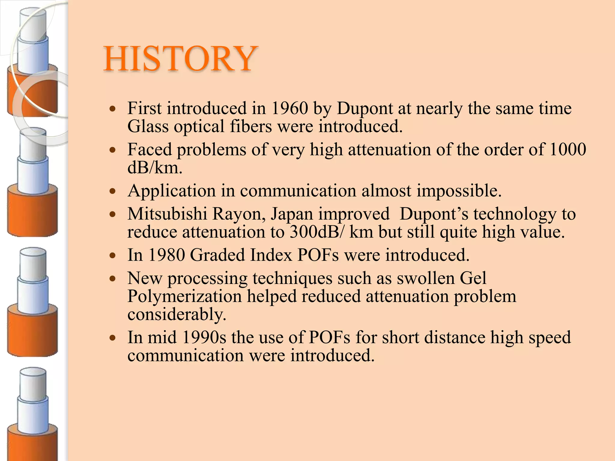
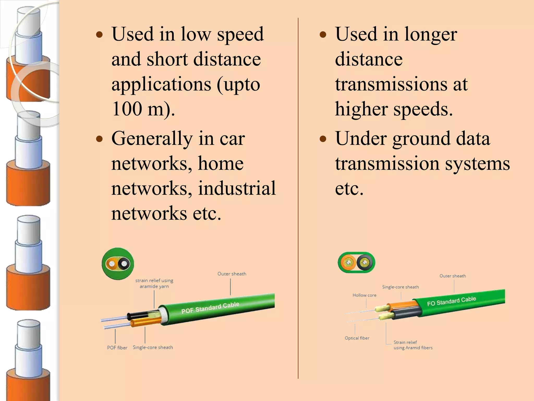
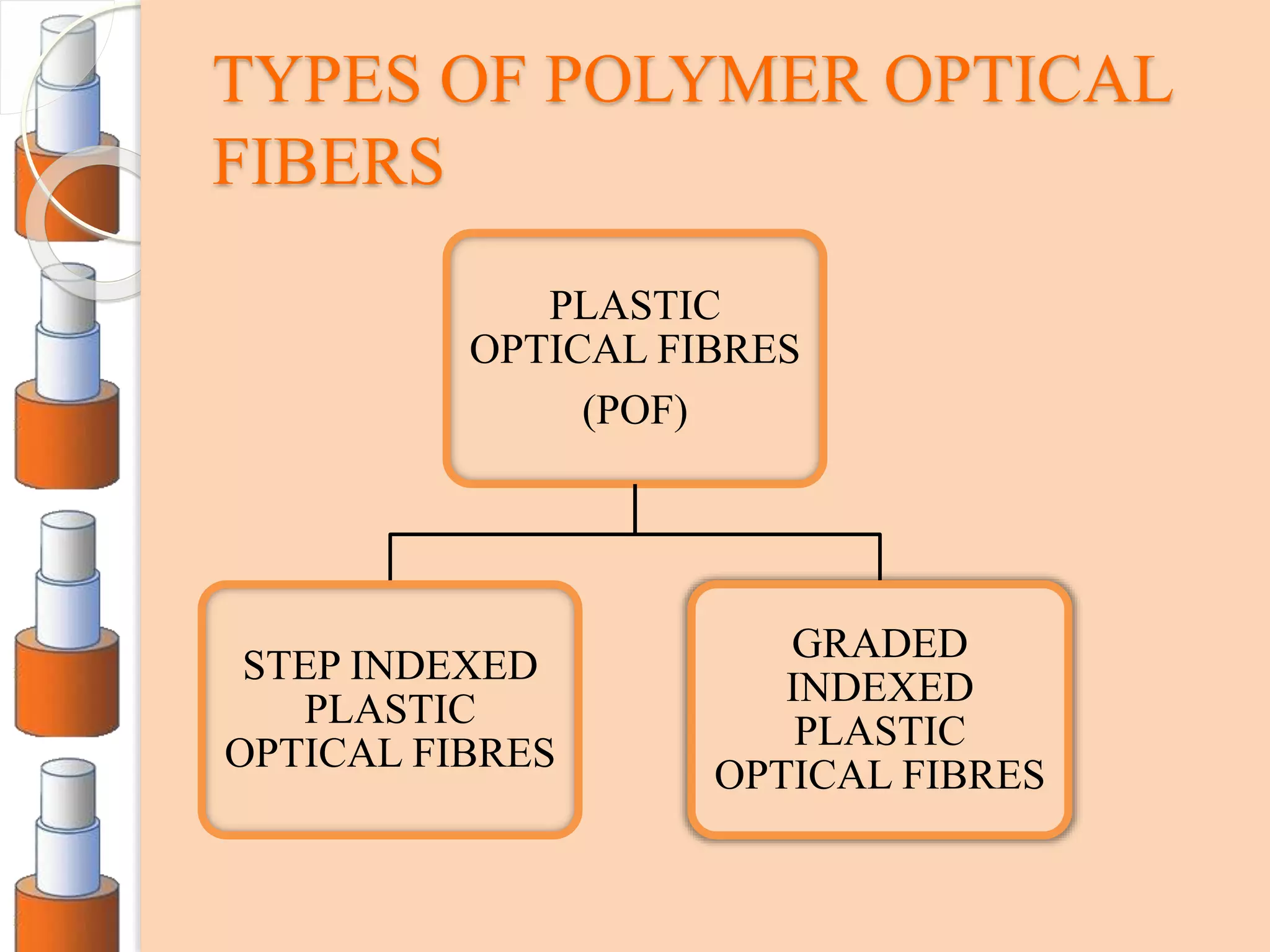
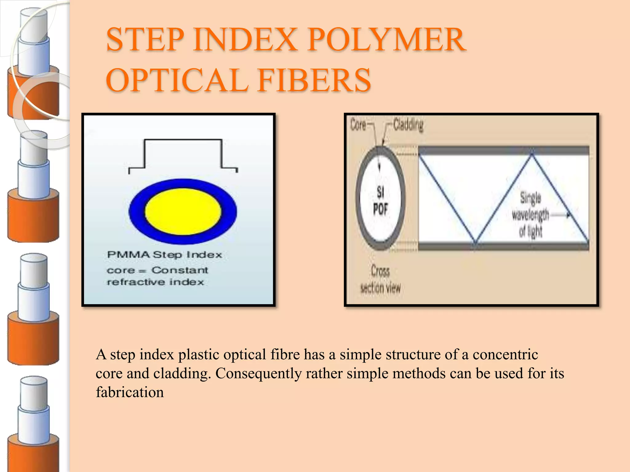
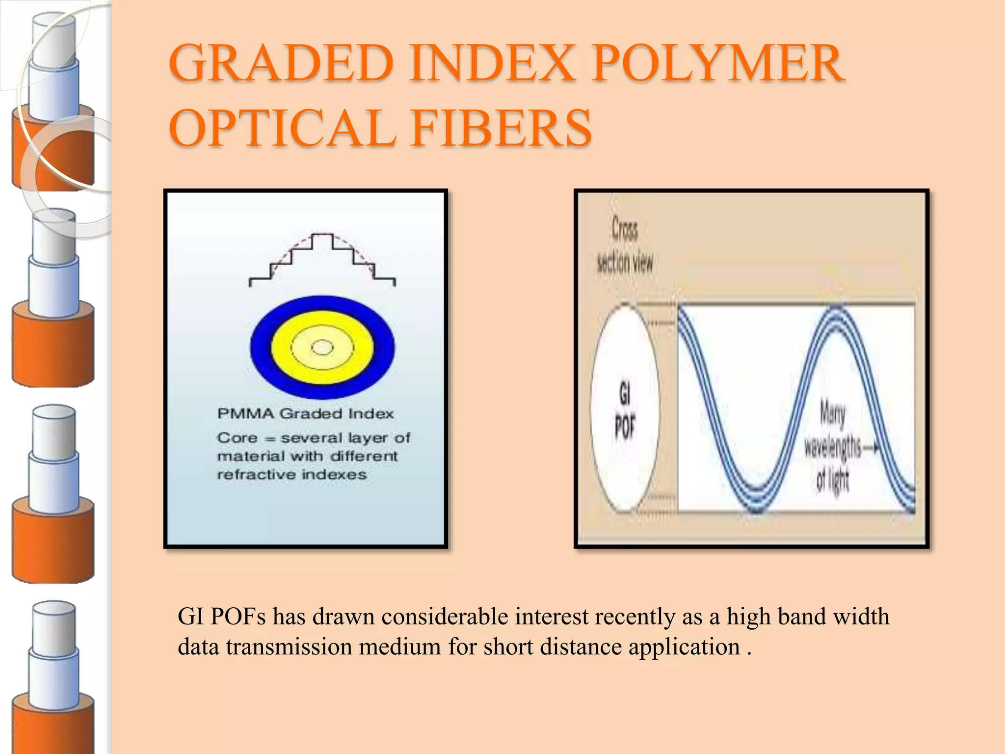
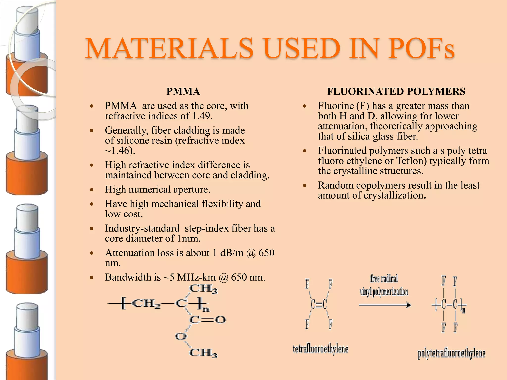
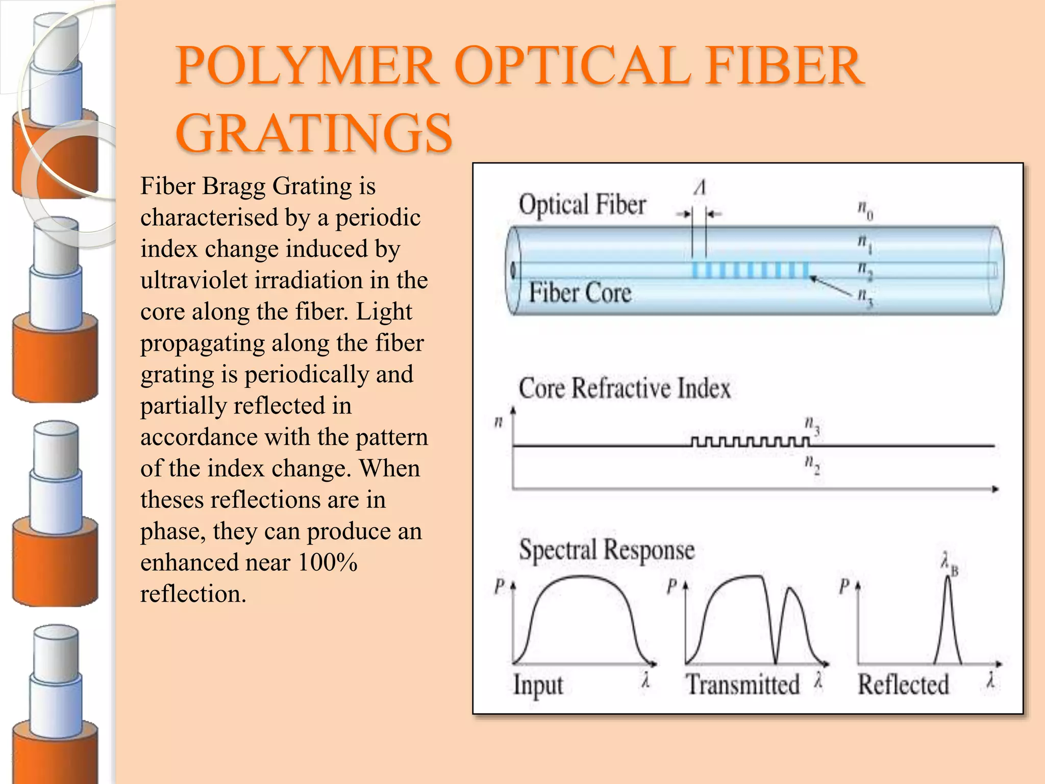
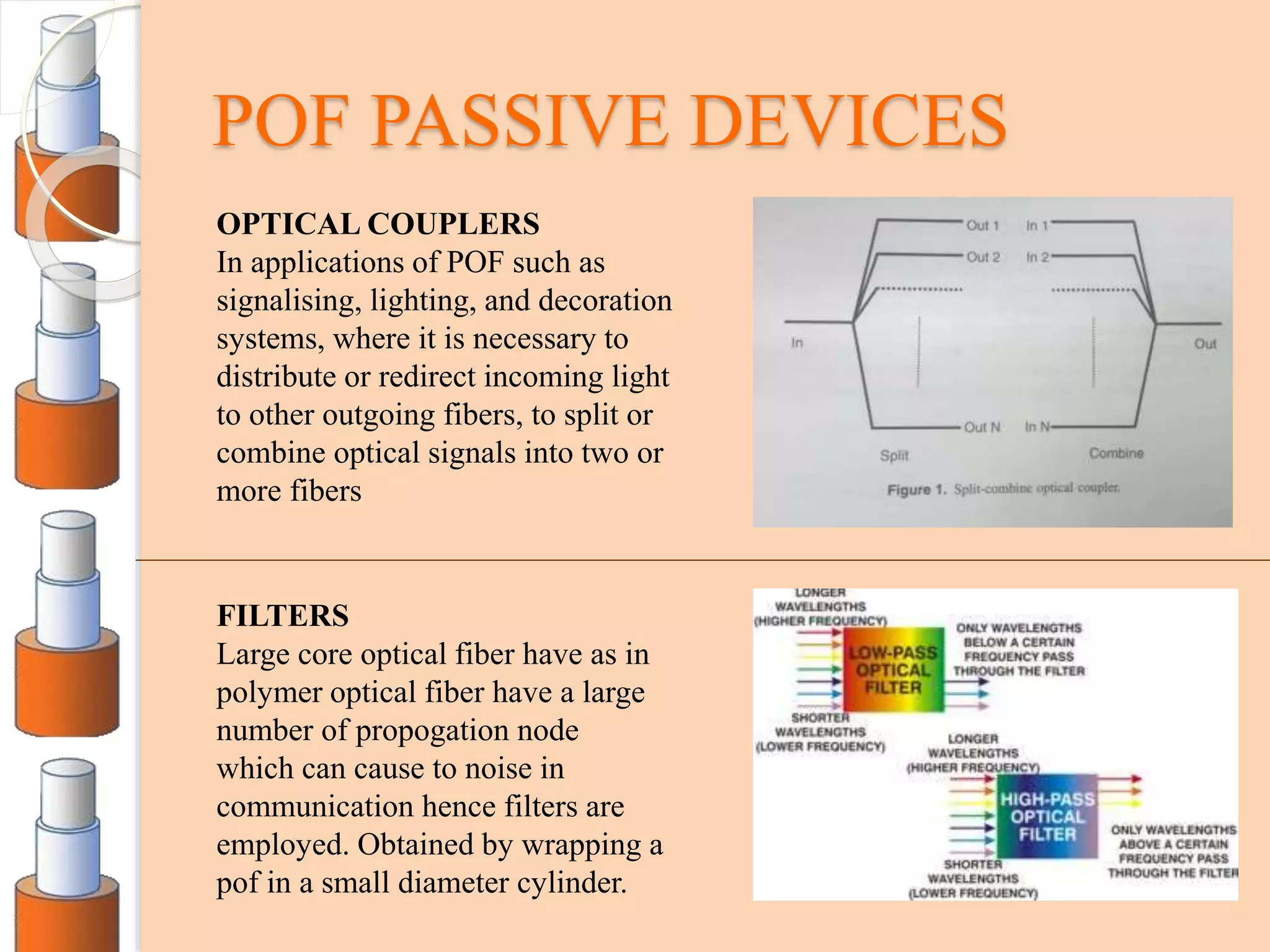
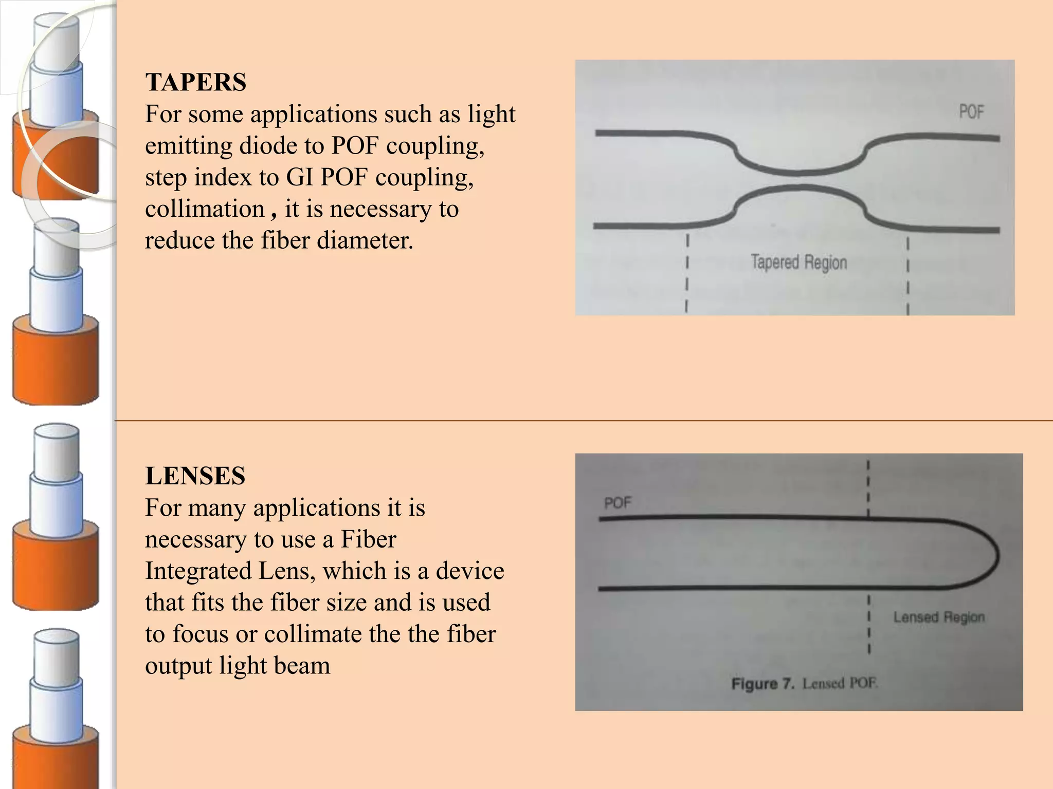
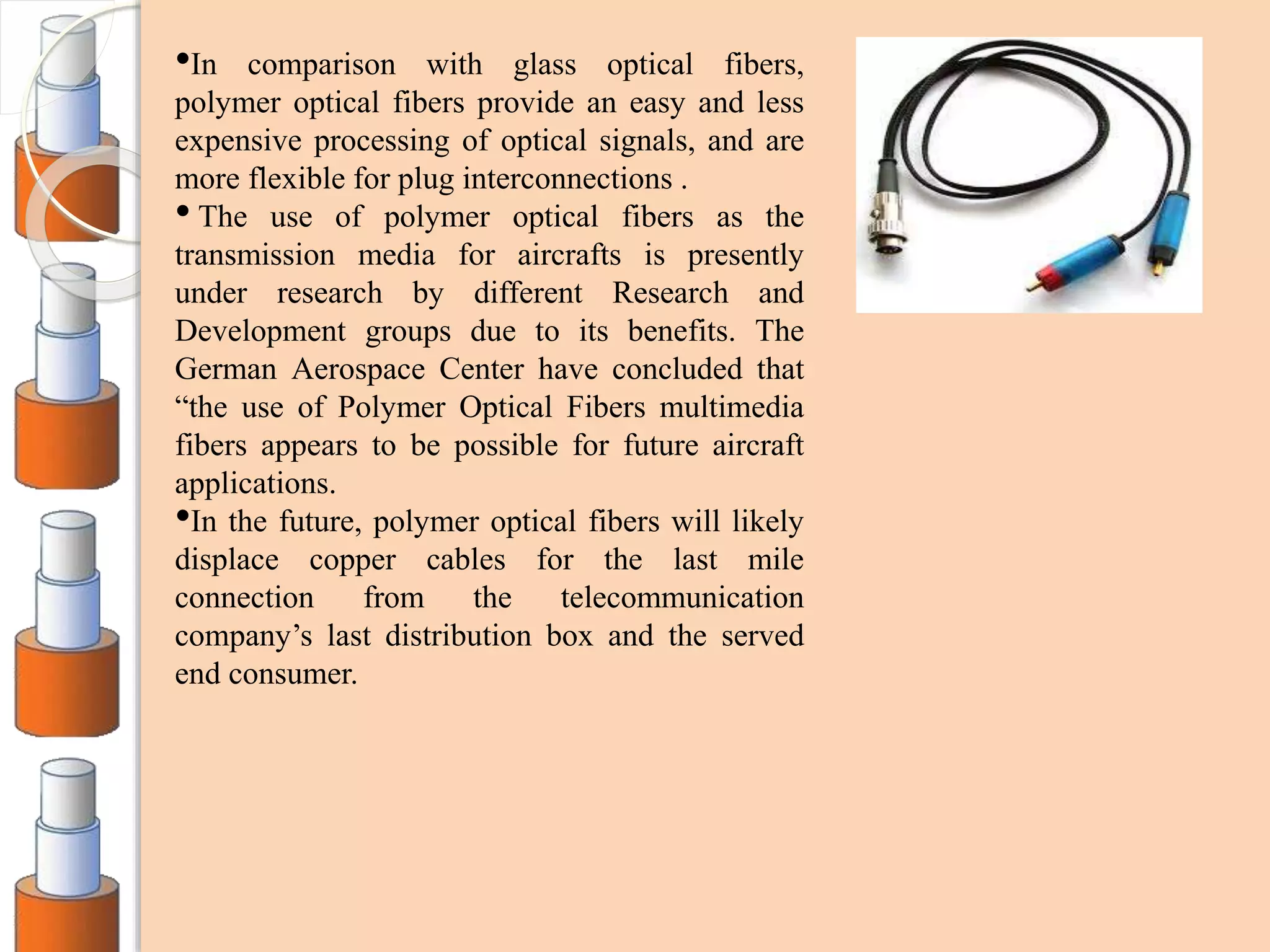
POLYMER OPTICAL
FIBERS
BY:-
Harshit Agarwal.
TOPICS TO BE DISCUSSED
 Introduction
 Principle Of Optical Fiber Communication
 History Of Polymer Optical Fiber
 Comparison of Polymer and Glass Optical Fiber
 Classification Of Pofs
 Materials Used In Pofs
 Application Of Pofs
 Fabrication Of Pofs
 Fabrication Of Si- Pofs
 Fabrication Of GI- Pofs
 Polymer Optical Fiber
 Plastic Optical Fiber Passive Devices
 Future Aspects Of Pofs
 Potential Of Pofs
INTRODUCTION
 An optical fiber (or optical
fiber) is a flexible, transparent
fiber made by drawing glass or
plastic to a diameter slightly
thicker than that of a human
hair. Optical fibers are used
most often as a means to
transmit light between the two
ends of the fiber and find wide
usage in fiber-optic
communications, where they
permit transmission over longer
distances and at
higher bandwidths
 Plastic optical fiber (POF)is
an optical fiber that is made out
of polymer. Similar to glass
optical fiber, POF transmits
light (for illumination or data)
through the core of the fiber.
PRINCIPLE OF OPTICAL FIBER
COMMUNICATION
Principle of operation
- Total Internal
Reflection
OPTICAL FIBER
HISTORY
 First introduced in 1960 by Dupont at nearly the same time
Glass optical fibers were introduced.
 Faced problems of very high attenuation of the order of 1000
dB/km.
 Application in communication almost impossible.
 Mitsubishi Rayon, Japan improved Dupont’s technology to
reduce attenuation to 300dB/ km but still quite high value.
 In 1980 Graded Index POFs were introduced.
 New processing techniques such as swollen Gel
Polymerization helped reduced attenuation problem
considerably.
 In mid 1990s the use of POFs for short distance high speed
communication were introduced.
COMPARISON B/W POFs & GOFs
POLYMER OPTICAL FIBER
 Plastic optical fiber, polymer
optical fiber is an optical fiber
which is made out of plastic.
It comprises of PMMA as the
core that facilitates the
transmission of light, and
fluorinated polymers as the
cladding material.
 Simpler and less expensive
components.
 Greater flexibility and light
weight.
 Bit rate upto 10Gbps.
GLASS OPTICAL FIBERS
 Glass optical fiber, just as its
name shows, is an optical
fiber made of glass. Being a
delicate type of optical fiber,
it cannot be cut, spliced or
repaired.
 Difficult handling and
delicate.
 Less resistant to flexibility
and accidental breakage.
 Higher information
transmission capacity & lower
losses.
 Used in low speed
and short distance
applications (upto
100 m).
 Generally in car
networks, home
networks, industrial
networks etc.
 Used in longer
distance
transmissions at
higher speeds.
 Under ground data
transmission systems
etc.
TYPES OF POLYMER OPTICAL
FIBERS
PLASTIC
OPTICAL FIBRES
(POF)
STEP INDEXED
PLASTIC
OPTICAL FIBRES
GRADED
INDEXED
PLASTIC
OPTICAL FIBRES
STEP INDEX POLYMER
OPTICAL FIBERS
A step index plastic optical fibre has a simple structure of a concentric
core and cladding. Consequently rather simple methods can be used for its
fabrication
GRADED INDEX POLYMER
OPTICAL FIBERS
GI POFs has drawn considerable interest recently as a high band width
data transmission medium for short distance application .
MATERIALS USED IN POFs
PMMA
 PMMA are used as the core, with
refractive indices of 1.49.
 Generally, fiber cladding is made
of silicone resin (refractive index
~1.46).
 High refractive index difference is
maintained between core and cladding.
 High numerical aperture.
 Have high mechanical flexibility and
low cost.
 Industry-standard step-index fiber has a
core diameter of 1mm.
 Attenuation loss is about 1 dB/m @ 650
nm.
 Bandwidth is ~5 MHz-km @ 650 nm.
FLUORINATED POLYMERS
 Fluorine (F) has a greater mass than
both H and D, allowing for lower
attenuation, theoretically approaching
that of silica glass fiber.
 Fluorinated polymers such a s poly tetra
fluoro ethylene or Teflon) typically form
the crystalline structures.
 Random copolymers result in the least
amount of crystallization.
APPLICATIONS
Currently the application of POFs can be
divided into four major categories:
 Lighting
 Communications.
 Sensors.
 Automobiles.
LIGHTING
 Decorations- lamps
and pools.
 Inspection of
mechanical welds in
pipes and engines
(airlanes, rockets and
automobiles).
 Medical
applications-
Endiscopes,
Bronchoscpoes,
Laproscopes
COMMUNICATION
•Research is being conducted to
reduce attenuation and increase
bandwidth to increase usage in
long distance communication.
•Ideal for short distance
network cabing
- New standard for LAN
cabling.
-Material cost fall between
copper and glass.
-Ease of installation.
•Gigabit Ethernet- Transport of
1.25Gbit/s Ethernet traffic over
900 m has been demonstrated
successfully.
SENSORS
 Optical measurement of flow, biofilm growth, toxicity, rotation,
humidity, fluoroscence.
 Humidity measurement
 - POG with PVA film.
 -Oil insulated power equipment.
 Toxicity biosensors.
- The fluoroscence produced by biological reaction is collected and
transmitted by POF.
AUTOMOBILES
•The number of electronic devices in
a car increases year by year,
primarily due to an increase in the
entertainment equipment desired for
modern passenger cars.
•This ubiquitous connection need is
a huge problem in networking
system designs for automotive
fiber from the viewpoint of both
physical space and system load.
Consequently, POF is specified in
the MOST standard to achieve the
lowest overall system weight and
easiest connectivity
FABRICATION OF POFs
STEP INDEXED
POLYMER
OPTICAL FIBRES
Continous Extrusion
Method
Preform Method
GRADED INDEXED
POLYMER
OPTICAL FIBRES
Photo-
Copolymerisaton
Swollen Gel
Polymerisation
Closed Co-Extrusion
Method
Centrifugal Method
FABRICATION OF STEP INDEX
POFs
A step Indexed plastic optical fiber has a simple
structure of a concentric core aand cladding.
Consequently rather simple fabrication techniques can
be applied for its fabrication, these techniques are
described as under.
1. Continous Extrusion Technique.
2. Preform Method
CONTINOUS EXTRUSION
METHOD
The polymer which becomes
the core of SI- POF is then
fed into a extruder by a gear
pump. The extruder is
capable of devolatalisation,
which removes monomer
residue and returns them to
the reactor. The core material
and the cladding material,
which are fed by separate
extruders, proceed into a
extrusion die where
concentric core - cladding
structure of an SI- POF is
formed.
PREFORM METHOD (SI POFs)
Method involves
two stages:
1. A cylindrical
preform 1-5 cm
in diameter and
upto 1 m in
length is made.
2. The preform is
drawn into a
fiber by heat
drawing
process.
FABRICATION OF GI- POFs
GI- POF has drawn considerable attention in the recent past as a high
bandwidth data transmission medium. The bandwidth of the POF is
maximized by optimizing the Distribution of Refractive Index.
Thus in manufacturing of GI- POF, the obtainable bandwidth of a
GI POF is directly related to the ability to control profile. To date
several methods have been proposed to for the manufacture of GI
POF. These methods are described in the upcoming sections.
 Photo copolymrization.
 Swollen Gel Polymerization.
 Closed Extrusion Method.
 Centrifugal Method.
PHOTO COPOLYMERISATION
(GI POFs)
• A 2.9 mm diameter glass tube
was was filled with a monomer
mixture methyl methacrylate and
vinyl benzoate and an initiator
benzoyl per oxide. the glass tube
reactor was then positioned
vertically in a constant
temperature chamber and rotated
about its vertical axis
• It is irradiated by UV. the UV
radiation was applied locally by
using a shade while the UV lamp
transversed from the bottom of
the tubular reactor to the top at a
constant speed.
SWOLLEN GEL
COPOLYMERIZATION (GI POFs)
A two stage process:
1. The monomer mixture is filled in the polymer tube to form gel at a lower
temperature to form a gel without significant copolymerization.
2. The temperature is raised to polymerization temperature to polymerize the
monomer, hence a rod is formed, which can be drawn into graded index
polymer optical fibre.
CLOSED CO EXTRUSION
METHOD (GI POFs)
• Versatile technology for making GI
POFs.
•The figure shows a schematic
diagram of the a N layer internal
diffusion and surface evaporation co
extrusion process.
•The tanks labeled 1- N are filled
with polymer melts.
•They are arranged so that when fed
to the concentric die the materials are
in decreasing order of the refractive
index of the polymers.
•It is thed passed through a hardening
zone H and is then receives by rolls.
CENTRIFUGAL METHOD
(GI POFs)
The centrifugal method is regarded as a potential method for the
preparation of the GI polymer rods because of the ability to
form large diameter GI rods. The figure here shows the
schematic representation of the preparation of the GI polymeric
rods by centrifugal method. Many aspects of this method are still
being studied
POLYMER OPTICAL FIBER
GRATINGS
Fiber Bragg Grating is
characterised by a periodic
index change induced by
ultraviolet irradiation in the
core along the fiber. Light
propagating along the fiber
grating is periodically and
partially reflected in
accordance with the pattern
of the index change. When
theses reflections are in
phase, they can produce an
enhanced near 100%
reflection.
FABRICATION OF POF
GRATINGS
 ABLATION: This involves melting and burning the polymer
surface.
 CHAIN SCISSION: This involves breaking the polymer chains,
thus decreasing the chain density, which in turns reduces the
refractive index.
 CROSS LINKING: This involves inducing free radicals and then
giving rise to the combination of polymer chains. This has the effect
of increasing the density of chains, thus increasing the refractive
index of the polymer.
 PHOTO POLYMERISATION: The incident light generates free
radicals , thus causing the polymerization of unreacted monomer
within the polymer. As a result, the polymerization density increases
and the refractive index increases accordingly.
POF PASSIVE DEVICES
OPTICAL COUPLERS
In applications of POF such as
signalising, lighting, and decoration
systems, where it is necessary to
distribute or redirect incoming light
to other outgoing fibers, to split or
combine optical signals into two or
more fibers
FILTERS
Large core optical fiber have as in
polymer optical fiber have a large
number of propogation node
which can cause to noise in
communication hence filters are
employed. Obtained by wrapping a
pof in a small diameter cylinder.
TAPERS
For some applications such as light
emitting diode to POF coupling,
step index to GI POF coupling,
collimation , it is necessary to
reduce the fiber diameter.
LENSES
For many applications it is
necessary to use a Fiber
Integrated Lens, which is a device
that fits the fiber size and is used
to focus or collimate the the fiber
output light beam
FUTURE ASPECTS
 Polymer Optic
Fibers Polymer
optical fibers
offer many
benefits when
compared to
other data
communication
solutions such as
copper cables,
wireless
communication
systems, and
glass fiber.
•In comparison with glass optical fibers,
polymer optical fibers provide an easy and less
expensive processing of optical signals, and are
more flexible for plug interconnections .
• The use of polymer optical fibers as the
transmission media for aircrafts is presently
under research by different Research and
Development groups due to its benefits. The
German Aerospace Center have concluded that
“the use of Polymer Optical Fibers multimedia
fibers appears to be possible for future aircraft
applications.
•In the future, polymer optical fibers will likely
displace copper cables for the last mile
connection from the telecommunication
company’s last distribution box and the served
end consumer.
REFERENCES
 Hari Singh Nalwa.(Ed.).(2004). Polymer Optical
Fibers. American Scientific Publishers.
• Chang-Won Park. Fabrication Techniques for Plastic Optical Fibers. USA
• Wen-Chang Chen,
Jui-Hsiang Liu, Yung Chang, Ming-Hsin Wei, and Hong-Wen Su. Gradient-
Index Polymer Optical Fibers: Analysis of Fabrication Techniques. Taiwan.
• Giok-Djan Khoe, Henrie van den Boom,
and Idelfonso Tafur Monroy. High Capacity Transmission System. The
Netherlands
• G. D. Peng and P. L. Chu. Polymer Optical Fiber Gratings, Australia.
• Liliana R. Kawase. Plastic Optical Fiber Passive Device. Brazil.
 An overview on fabrication method for polymer optical fibers.
Christian -Alexander Bunge. www.academia.edu
 Plastic optical fiber Vs Glass optical Fiber. Retrieved from
www.fiberopticsshare.com.
 Polymer optical fiber (n.d). Retrieved February 5, 2016, from
en.wikipedia.org/wiki/Plastic_optical_fiber.
Polymer optical fibers

Polymer optical fibers

  • 1.
  • 2.
    TOPICS TO BEDISCUSSED  Introduction  Principle Of Optical Fiber Communication  History Of Polymer Optical Fiber  Comparison of Polymer and Glass Optical Fiber  Classification Of Pofs  Materials Used In Pofs  Application Of Pofs  Fabrication Of Pofs  Fabrication Of Si- Pofs  Fabrication Of GI- Pofs  Polymer Optical Fiber  Plastic Optical Fiber Passive Devices  Future Aspects Of Pofs  Potential Of Pofs
  • 3.
    INTRODUCTION  An opticalfiber (or optical fiber) is a flexible, transparent fiber made by drawing glass or plastic to a diameter slightly thicker than that of a human hair. Optical fibers are used most often as a means to transmit light between the two ends of the fiber and find wide usage in fiber-optic communications, where they permit transmission over longer distances and at higher bandwidths  Plastic optical fiber (POF)is an optical fiber that is made out of polymer. Similar to glass optical fiber, POF transmits light (for illumination or data) through the core of the fiber.
  • 4.
    PRINCIPLE OF OPTICALFIBER COMMUNICATION Principle of operation - Total Internal Reflection OPTICAL FIBER
  • 5.
    HISTORY  First introducedin 1960 by Dupont at nearly the same time Glass optical fibers were introduced.  Faced problems of very high attenuation of the order of 1000 dB/km.  Application in communication almost impossible.  Mitsubishi Rayon, Japan improved Dupont’s technology to reduce attenuation to 300dB/ km but still quite high value.  In 1980 Graded Index POFs were introduced.  New processing techniques such as swollen Gel Polymerization helped reduced attenuation problem considerably.  In mid 1990s the use of POFs for short distance high speed communication were introduced.
  • 6.
    COMPARISON B/W POFs& GOFs POLYMER OPTICAL FIBER  Plastic optical fiber, polymer optical fiber is an optical fiber which is made out of plastic. It comprises of PMMA as the core that facilitates the transmission of light, and fluorinated polymers as the cladding material.  Simpler and less expensive components.  Greater flexibility and light weight.  Bit rate upto 10Gbps. GLASS OPTICAL FIBERS  Glass optical fiber, just as its name shows, is an optical fiber made of glass. Being a delicate type of optical fiber, it cannot be cut, spliced or repaired.  Difficult handling and delicate.  Less resistant to flexibility and accidental breakage.  Higher information transmission capacity & lower losses.
  • 7.
     Used inlow speed and short distance applications (upto 100 m).  Generally in car networks, home networks, industrial networks etc.  Used in longer distance transmissions at higher speeds.  Under ground data transmission systems etc.
  • 8.
    TYPES OF POLYMEROPTICAL FIBERS PLASTIC OPTICAL FIBRES (POF) STEP INDEXED PLASTIC OPTICAL FIBRES GRADED INDEXED PLASTIC OPTICAL FIBRES
  • 9.
    STEP INDEX POLYMER OPTICALFIBERS A step index plastic optical fibre has a simple structure of a concentric core and cladding. Consequently rather simple methods can be used for its fabrication
  • 10.
    GRADED INDEX POLYMER OPTICALFIBERS GI POFs has drawn considerable interest recently as a high band width data transmission medium for short distance application .
  • 11.
    MATERIALS USED INPOFs PMMA  PMMA are used as the core, with refractive indices of 1.49.  Generally, fiber cladding is made of silicone resin (refractive index ~1.46).  High refractive index difference is maintained between core and cladding.  High numerical aperture.  Have high mechanical flexibility and low cost.  Industry-standard step-index fiber has a core diameter of 1mm.  Attenuation loss is about 1 dB/m @ 650 nm.  Bandwidth is ~5 MHz-km @ 650 nm. FLUORINATED POLYMERS  Fluorine (F) has a greater mass than both H and D, allowing for lower attenuation, theoretically approaching that of silica glass fiber.  Fluorinated polymers such a s poly tetra fluoro ethylene or Teflon) typically form the crystalline structures.  Random copolymers result in the least amount of crystallization.
  • 12.
    APPLICATIONS Currently the applicationof POFs can be divided into four major categories:  Lighting  Communications.  Sensors.  Automobiles.
  • 13.
    LIGHTING  Decorations- lamps andpools.  Inspection of mechanical welds in pipes and engines (airlanes, rockets and automobiles).  Medical applications- Endiscopes, Bronchoscpoes, Laproscopes
  • 14.
    COMMUNICATION •Research is beingconducted to reduce attenuation and increase bandwidth to increase usage in long distance communication. •Ideal for short distance network cabing - New standard for LAN cabling. -Material cost fall between copper and glass. -Ease of installation. •Gigabit Ethernet- Transport of 1.25Gbit/s Ethernet traffic over 900 m has been demonstrated successfully.
  • 15.
    SENSORS  Optical measurementof flow, biofilm growth, toxicity, rotation, humidity, fluoroscence.  Humidity measurement  - POG with PVA film.  -Oil insulated power equipment.  Toxicity biosensors. - The fluoroscence produced by biological reaction is collected and transmitted by POF.
  • 16.
    AUTOMOBILES •The number ofelectronic devices in a car increases year by year, primarily due to an increase in the entertainment equipment desired for modern passenger cars. •This ubiquitous connection need is a huge problem in networking system designs for automotive fiber from the viewpoint of both physical space and system load. Consequently, POF is specified in the MOST standard to achieve the lowest overall system weight and easiest connectivity
  • 17.
    FABRICATION OF POFs STEPINDEXED POLYMER OPTICAL FIBRES Continous Extrusion Method Preform Method GRADED INDEXED POLYMER OPTICAL FIBRES Photo- Copolymerisaton Swollen Gel Polymerisation Closed Co-Extrusion Method Centrifugal Method
  • 18.
    FABRICATION OF STEPINDEX POFs A step Indexed plastic optical fiber has a simple structure of a concentric core aand cladding. Consequently rather simple fabrication techniques can be applied for its fabrication, these techniques are described as under. 1. Continous Extrusion Technique. 2. Preform Method
  • 19.
    CONTINOUS EXTRUSION METHOD The polymerwhich becomes the core of SI- POF is then fed into a extruder by a gear pump. The extruder is capable of devolatalisation, which removes monomer residue and returns them to the reactor. The core material and the cladding material, which are fed by separate extruders, proceed into a extrusion die where concentric core - cladding structure of an SI- POF is formed.
  • 20.
    PREFORM METHOD (SIPOFs) Method involves two stages: 1. A cylindrical preform 1-5 cm in diameter and upto 1 m in length is made. 2. The preform is drawn into a fiber by heat drawing process.
  • 21.
    FABRICATION OF GI-POFs GI- POF has drawn considerable attention in the recent past as a high bandwidth data transmission medium. The bandwidth of the POF is maximized by optimizing the Distribution of Refractive Index. Thus in manufacturing of GI- POF, the obtainable bandwidth of a GI POF is directly related to the ability to control profile. To date several methods have been proposed to for the manufacture of GI POF. These methods are described in the upcoming sections.  Photo copolymrization.  Swollen Gel Polymerization.  Closed Extrusion Method.  Centrifugal Method.
  • 22.
    PHOTO COPOLYMERISATION (GI POFs) •A 2.9 mm diameter glass tube was was filled with a monomer mixture methyl methacrylate and vinyl benzoate and an initiator benzoyl per oxide. the glass tube reactor was then positioned vertically in a constant temperature chamber and rotated about its vertical axis • It is irradiated by UV. the UV radiation was applied locally by using a shade while the UV lamp transversed from the bottom of the tubular reactor to the top at a constant speed.
  • 23.
    SWOLLEN GEL COPOLYMERIZATION (GIPOFs) A two stage process: 1. The monomer mixture is filled in the polymer tube to form gel at a lower temperature to form a gel without significant copolymerization. 2. The temperature is raised to polymerization temperature to polymerize the monomer, hence a rod is formed, which can be drawn into graded index polymer optical fibre.
  • 24.
    CLOSED CO EXTRUSION METHOD(GI POFs) • Versatile technology for making GI POFs. •The figure shows a schematic diagram of the a N layer internal diffusion and surface evaporation co extrusion process. •The tanks labeled 1- N are filled with polymer melts. •They are arranged so that when fed to the concentric die the materials are in decreasing order of the refractive index of the polymers. •It is thed passed through a hardening zone H and is then receives by rolls.
  • 25.
    CENTRIFUGAL METHOD (GI POFs) Thecentrifugal method is regarded as a potential method for the preparation of the GI polymer rods because of the ability to form large diameter GI rods. The figure here shows the schematic representation of the preparation of the GI polymeric rods by centrifugal method. Many aspects of this method are still being studied
  • 26.
    POLYMER OPTICAL FIBER GRATINGS FiberBragg Grating is characterised by a periodic index change induced by ultraviolet irradiation in the core along the fiber. Light propagating along the fiber grating is periodically and partially reflected in accordance with the pattern of the index change. When theses reflections are in phase, they can produce an enhanced near 100% reflection.
  • 27.
    FABRICATION OF POF GRATINGS ABLATION: This involves melting and burning the polymer surface.  CHAIN SCISSION: This involves breaking the polymer chains, thus decreasing the chain density, which in turns reduces the refractive index.  CROSS LINKING: This involves inducing free radicals and then giving rise to the combination of polymer chains. This has the effect of increasing the density of chains, thus increasing the refractive index of the polymer.  PHOTO POLYMERISATION: The incident light generates free radicals , thus causing the polymerization of unreacted monomer within the polymer. As a result, the polymerization density increases and the refractive index increases accordingly.
  • 28.
    POF PASSIVE DEVICES OPTICALCOUPLERS In applications of POF such as signalising, lighting, and decoration systems, where it is necessary to distribute or redirect incoming light to other outgoing fibers, to split or combine optical signals into two or more fibers FILTERS Large core optical fiber have as in polymer optical fiber have a large number of propogation node which can cause to noise in communication hence filters are employed. Obtained by wrapping a pof in a small diameter cylinder.
  • 29.
    TAPERS For some applicationssuch as light emitting diode to POF coupling, step index to GI POF coupling, collimation , it is necessary to reduce the fiber diameter. LENSES For many applications it is necessary to use a Fiber Integrated Lens, which is a device that fits the fiber size and is used to focus or collimate the the fiber output light beam
  • 30.
    FUTURE ASPECTS  PolymerOptic Fibers Polymer optical fibers offer many benefits when compared to other data communication solutions such as copper cables, wireless communication systems, and glass fiber.
  • 31.
    •In comparison withglass optical fibers, polymer optical fibers provide an easy and less expensive processing of optical signals, and are more flexible for plug interconnections . • The use of polymer optical fibers as the transmission media for aircrafts is presently under research by different Research and Development groups due to its benefits. The German Aerospace Center have concluded that “the use of Polymer Optical Fibers multimedia fibers appears to be possible for future aircraft applications. •In the future, polymer optical fibers will likely displace copper cables for the last mile connection from the telecommunication company’s last distribution box and the served end consumer.
  • 32.
    REFERENCES  Hari SinghNalwa.(Ed.).(2004). Polymer Optical Fibers. American Scientific Publishers. • Chang-Won Park. Fabrication Techniques for Plastic Optical Fibers. USA • Wen-Chang Chen, Jui-Hsiang Liu, Yung Chang, Ming-Hsin Wei, and Hong-Wen Su. Gradient- Index Polymer Optical Fibers: Analysis of Fabrication Techniques. Taiwan. • Giok-Djan Khoe, Henrie van den Boom, and Idelfonso Tafur Monroy. High Capacity Transmission System. The Netherlands • G. D. Peng and P. L. Chu. Polymer Optical Fiber Gratings, Australia. • Liliana R. Kawase. Plastic Optical Fiber Passive Device. Brazil.  An overview on fabrication method for polymer optical fibers. Christian -Alexander Bunge. www.academia.edu  Plastic optical fiber Vs Glass optical Fiber. Retrieved from www.fiberopticsshare.com.  Polymer optical fiber (n.d). Retrieved February 5, 2016, from en.wikipedia.org/wiki/Plastic_optical_fiber.

Editor's Notes

  • #27 It is a method used in glass optical fiber to imrove transmissions and reduce losses. Introdeuced in POF by doping and base material is significantly photosensitive at uv wavelengths. POF gratings can be fabricated by making use of these photo senstivities.
  • #28 These are the four methods for introducing gratings in polymer optical fiber.