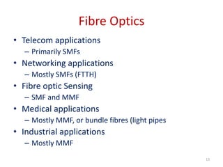
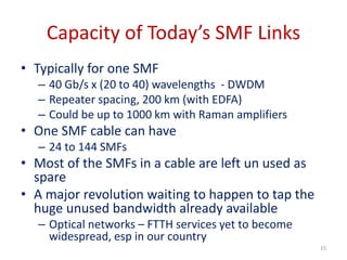
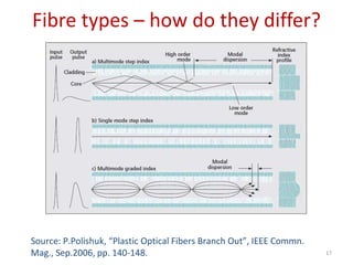
Optical Fibre communication
Overview
• Brief introduction to Optical Fibre
communication
• Single mode fibre (SMF) based FO links
• Multimode fibre (MMF) based FO links
• Short haul, high speed applications
• Modern trends in MMF based
communications
– Glass optical fibres (GOF)
– Plastic optical fibres (POF)
2
Introduction: Major milestones in
Electrical Communication
• 1838 – Samuel F.B. Morse invented Telegraphy
• 1866 – first transatlantic telegraph cable
• 1876 – Alexander Graham Bell invented
Telephone
• 1905 – Triode based Electronic amplifier
• 1940 – first coaxial-cable system (3 MHz –
3,000 voice channels or ONE
television channel)
• 1948 – first microwave system (4 GHz)
• 1975 – the most advanced coaxial system with a
bit rate of 274 Mb/s
3
Communication Systems of the 20th
Century
• Wire – Telegraphy (2 wires for telegraph
transmission – simplex & duplex)
• Wire – Telephony (2 wires for telephone
transmission of 1 channel)
• Carrier telephony (long-distance telephony
for multiple channels – 4,8,16)
• Coaxial cable systems (for 32 channel
PCM systems – 32x64kb/s = 2.048 Mb/s)
4
Problems of Electrical Communication
systems
• Affected by EMI
• Low bandwidth (4 kHz – telephone,
100-500 MHz per km – coaxial cable )
• High attenuation (20 dB/km – typically)
• High system cost
– due to too many repeaters for a given Bandwidth/
data rate
– Eg. 32 channel (2.048 Mbps) PCM link required one
repeater every 2 km
• Prone to tapping
• Bulky
5
History of Optical Fibre Communications
• 1966 – suggestion to use optical fiber (Kao &
Hockham)
• 1970 – Corning Glass optical fiber with 20 dB/km
near 1 μm
• 1970 - Semiconductor Laser with CW operation
at room temp.
• 1980 onwards – wide spread use of Optical
Fiber Communication using SMF and MMF
• 1990 – used Optical amplification (for increased repeater
spacing) and Wavelength-division multiplexing (WDM)
for increased data rate.
– Resulted in a data rate of 10 Tb/s by 2001.
6
Advantages of Optical Fiber
Communication (Fiber Optics)
• Very high bandwidth (10 - 500 GHz, typ.)
• Very low attenuation (lowest 0.16 dB/km)
• Immune to EMI
• Data security (almost impossible to tap
information)
• Lower system cost (fewer repeaters due to low
attenuation of fibers)
• Small size and low weight
• Very low Bit Error Rate ( < 10-10 typically)
Basics of Optical Fibre
Communication
An Optical Fiber Communication System
consists of
• Transmitter
– Optical source (LED or Laser diode) + driver
circuit
• Optical Fibre
– Single mode fibre, or
– Multimode fibre
• Receiver
– Photodetector PIN or APD + receiver circuit
A Modern Optical Communication
System for Telecom with WDM and
Optical Amplifiers
Source: Gerd Keiser, Optical Fiber
Communications, 4th ed.,
McGraw-Hill, 2008: Chapter 10.
Transmission windows and
bandwidths
Transmission-bandwidths in the O
(1300nm)- and C(1550nm)-bands
Source: Gerd Keiser, Optical Fiber
Communications, 4th ed.,
McGraw-Hill, 2008: Chapter 10.
Source: Nobel Lecture, 2009, CK Kao, “Transmission of Light in
Fiber for Optical Communication”
Source: Nobel Lecture, 2009, CK Kao, “Transmission of Light in
Fiber for Optical Communication”
Fibre Optics
• Telecom applications
– Primarily SMFs
• Networking applications
– Mostly SMFs (FTTH)
• Fibre optic Sensing
– SMF and MMF
• Medical applications
– Mostly MMF, or bundle fibres (light pipes
• Industrial applications
– Mostly MMF
13
SMF vs MMF
• Single mode fibres – today’s work horse for
long haul telecom as well as optical networks
• Multimode fibres – not widely used for
communications as single mode fibres. any
advantages?
14
Capacity of Today’s SMF Links
• Typically for one SMF
– 40 Gb/s x (20 to 40) wavelengths - DWDM
– Repeater spacing, 200 km (with EDFA)
– Could be up to 1000 km with Raman amplifiers
• One SMF cable can have
– 24 to 144 SMFs
• Most of the SMFs in a cable are left un used as
spare
• A major revolution waiting to happen to tap the
huge unused bandwidth already available
– Optical networks – FTTH services yet to become
widespread, esp in our country
15
Why MMF?
• Easy to use and couple light
• Large alignment tolerances ( typically a few
µm) compared to SMF (sub µm)
• Cost effective (cheaper tools, and connectors)
• Lot of interest today for short-haul
communications
16
Fibre types – how do they differ?
17
Source: P.Polishuk, “Plastic Optical Fibers Branch Out”, IEEE Commn.
Mag., Sep.2006, pp. 140-148.
MMF Types
• Glass Optical Fibres (Graded-index)
– 50/125 µm, 62.5/125 µm, 100/140 µm
• Plastic Optical Fibres
– PMMA or PF
– Step index or Graded index
– A variety of dimensions
18
MMF – Glass (GOF)
• Very extensively used for short haul (up to 10
km) high data rate (up to 10 Gb/s) links
• The preferred choice for LAN applications
(1300nm, 62.5/125 µm GI MMF)
• Many other MMF experiments have been
reported with much higher data rates
19
20
2007: 40 Gb/s, 3.4 km, BL product of 136 Gb/s km
Scott S-H. Yam1, and Frank Achten, Toward 100 Gbits/s Ethernet with
broad wavelength window multimode fiber, J.Opt.Netw., Vol. 6, No. 5,
pp.527-534, May 2007.
21
I. Gasulla, J. Capmany, 1 Tb/s·km WDM Transmission over Multimode
Fibre Link, ECOC, 2008, Paper Tu.3.E.5.
2008: 10x 20 Gb/s, 62.5/125 μm silica MMF,
WDM using 10 DFB lasers.
Use of MMFs with different bandwidth
grades for 10 Gb/s
• OM1 grade fiber
– 62.5/125 µm; called legacy or original fiber that was
designed for use with LEDs (larger core dia); typically up to
100 Mb/s
• OM2 grade fiber
– 50/125 µm; improved bandwidth over OM1; used for
1Gb/s (750m) or 10 Gb/s (82m)
• OM3 grade fiber
– 50/125 µm; higher bandwidth than OM2; can support
10Gb/s up to 300m; used with VCSELs
• OM4 grade fiber
– 50/125 µm; bandwidth much higher than OM3; can be
used for both 1 Gb/s and 10 Gb/s with 850 nm VCSELs for
distances up to 550 m; suitable for future 40 and 100 Gb/s
Source: Gerd Keiser, Optical Fiber Communications,
5e, Chap 13, McGraw Hill, New Delhi
MMF – Plastic (POF)
• Emerging as a lower-cost alternative to glass fiber
or copper at medium distances and bit rates of 10
Gb/s.
• Manufacturers form POFs out of plastic materials
such as polystyrene, polycarbonates, and
polymethyl methacrylate (PMMA).
• These materials have transmission windows in
the visible range (520–780 nm).
• The loss of light transmitted at these wavelengths
is high, ranging from 150 dB/km for PMMA to
1000 dB/km for polystyrene and polycarbonates.
24
POF
• Glass fibres have losses
– of 0.2 dB/km for a single-mode fiber and
– less than 3 dB/km for multimode fibers.
– Used extensively for long length applications
• Plastic fibers have been relegated to short-
distance applications, typically of a few
hundred meters or less
25
Typical POF Applications
• Data applications
– Industrial control
– automobiles,
– Home networks
– Short data links
• Non-data applications
– sensors for detecting high energy particles
– Signs
– illumination,
• Today, the surge in POF production and use stems
from its use in data transmission.
26
Advantages of POF (over Glass Fibre or
Copper Wire)
• Simpler and less expensive components.
• Lighter weight.
• Operation in the visible spectrum.
• Greater flexibility, and resilience to bending, shock, and
vibration.
• Immunity to electromagnetic interference (EMI).
• Ease in handling and connecting (POF diameters are 1 mm
compared with 8–100 μm for glass).
• Use of simple and inexpensive test equipment.
• Greater safety than glass fibers or fiber slivers;
• glass requires a laser light source
• Transceivers require less power than copper transceivers.
27
Disadvantages
• High loss during transmission
• Bandwidths lower than SMFs
• A small number of providers of total systems
• A lack of standards
• A lack of awareness among users of how to install and
design with POFs
• Limited production, and Small number of systems and
suppliers
• Applications research is incomplete
• Incomplete certification programs from POF installers
• Lack of high temperature fibers (125°C)
28

Chapter-5-Optical-Fibre-communication.pptx

  • 1.
  • 2.
    Overview • Brief introductionto Optical Fibre communication • Single mode fibre (SMF) based FO links • Multimode fibre (MMF) based FO links • Short haul, high speed applications • Modern trends in MMF based communications – Glass optical fibres (GOF) – Plastic optical fibres (POF) 2
  • 3.
    Introduction: Major milestonesin Electrical Communication • 1838 – Samuel F.B. Morse invented Telegraphy • 1866 – first transatlantic telegraph cable • 1876 – Alexander Graham Bell invented Telephone • 1905 – Triode based Electronic amplifier • 1940 – first coaxial-cable system (3 MHz – 3,000 voice channels or ONE television channel) • 1948 – first microwave system (4 GHz) • 1975 – the most advanced coaxial system with a bit rate of 274 Mb/s 3
  • 4.
    Communication Systems ofthe 20th Century • Wire – Telegraphy (2 wires for telegraph transmission – simplex & duplex) • Wire – Telephony (2 wires for telephone transmission of 1 channel) • Carrier telephony (long-distance telephony for multiple channels – 4,8,16) • Coaxial cable systems (for 32 channel PCM systems – 32x64kb/s = 2.048 Mb/s) 4
  • 5.
    Problems of ElectricalCommunication systems • Affected by EMI • Low bandwidth (4 kHz – telephone, 100-500 MHz per km – coaxial cable ) • High attenuation (20 dB/km – typically) • High system cost – due to too many repeaters for a given Bandwidth/ data rate – Eg. 32 channel (2.048 Mbps) PCM link required one repeater every 2 km • Prone to tapping • Bulky 5
  • 6.
    History of OpticalFibre Communications • 1966 – suggestion to use optical fiber (Kao & Hockham) • 1970 – Corning Glass optical fiber with 20 dB/km near 1 μm • 1970 - Semiconductor Laser with CW operation at room temp. • 1980 onwards – wide spread use of Optical Fiber Communication using SMF and MMF • 1990 – used Optical amplification (for increased repeater spacing) and Wavelength-division multiplexing (WDM) for increased data rate. – Resulted in a data rate of 10 Tb/s by 2001. 6
  • 7.
    Advantages of OpticalFiber Communication (Fiber Optics) • Very high bandwidth (10 - 500 GHz, typ.) • Very low attenuation (lowest 0.16 dB/km) • Immune to EMI • Data security (almost impossible to tap information) • Lower system cost (fewer repeaters due to low attenuation of fibers) • Small size and low weight • Very low Bit Error Rate ( < 10-10 typically)
  • 8.
    Basics of OpticalFibre Communication An Optical Fiber Communication System consists of • Transmitter – Optical source (LED or Laser diode) + driver circuit • Optical Fibre – Single mode fibre, or – Multimode fibre • Receiver – Photodetector PIN or APD + receiver circuit
  • 9.
    A Modern OpticalCommunication System for Telecom with WDM and Optical Amplifiers Source: Gerd Keiser, Optical Fiber Communications, 4th ed., McGraw-Hill, 2008: Chapter 10.
  • 10.
    Transmission windows and bandwidths Transmission-bandwidthsin the O (1300nm)- and C(1550nm)-bands Source: Gerd Keiser, Optical Fiber Communications, 4th ed., McGraw-Hill, 2008: Chapter 10.
  • 11.
    Source: Nobel Lecture,2009, CK Kao, “Transmission of Light in Fiber for Optical Communication”
  • 12.
    Source: Nobel Lecture,2009, CK Kao, “Transmission of Light in Fiber for Optical Communication”
  • 13.
    Fibre Optics • Telecomapplications – Primarily SMFs • Networking applications – Mostly SMFs (FTTH) • Fibre optic Sensing – SMF and MMF • Medical applications – Mostly MMF, or bundle fibres (light pipes • Industrial applications – Mostly MMF 13
  • 14.
    SMF vs MMF •Single mode fibres – today’s work horse for long haul telecom as well as optical networks • Multimode fibres – not widely used for communications as single mode fibres. any advantages? 14
  • 15.
    Capacity of Today’sSMF Links • Typically for one SMF – 40 Gb/s x (20 to 40) wavelengths - DWDM – Repeater spacing, 200 km (with EDFA) – Could be up to 1000 km with Raman amplifiers • One SMF cable can have – 24 to 144 SMFs • Most of the SMFs in a cable are left un used as spare • A major revolution waiting to happen to tap the huge unused bandwidth already available – Optical networks – FTTH services yet to become widespread, esp in our country 15
  • 16.
    Why MMF? • Easyto use and couple light • Large alignment tolerances ( typically a few µm) compared to SMF (sub µm) • Cost effective (cheaper tools, and connectors) • Lot of interest today for short-haul communications 16
  • 17.
    Fibre types –how do they differ? 17 Source: P.Polishuk, “Plastic Optical Fibers Branch Out”, IEEE Commn. Mag., Sep.2006, pp. 140-148.
  • 18.
    MMF Types • GlassOptical Fibres (Graded-index) – 50/125 µm, 62.5/125 µm, 100/140 µm • Plastic Optical Fibres – PMMA or PF – Step index or Graded index – A variety of dimensions 18
  • 19.
    MMF – Glass(GOF) • Very extensively used for short haul (up to 10 km) high data rate (up to 10 Gb/s) links • The preferred choice for LAN applications (1300nm, 62.5/125 µm GI MMF) • Many other MMF experiments have been reported with much higher data rates 19
  • 20.
    20 2007: 40 Gb/s,3.4 km, BL product of 136 Gb/s km Scott S-H. Yam1, and Frank Achten, Toward 100 Gbits/s Ethernet with broad wavelength window multimode fiber, J.Opt.Netw., Vol. 6, No. 5, pp.527-534, May 2007.
  • 21.
    21 I. Gasulla, J.Capmany, 1 Tb/s·km WDM Transmission over Multimode Fibre Link, ECOC, 2008, Paper Tu.3.E.5. 2008: 10x 20 Gb/s, 62.5/125 μm silica MMF, WDM using 10 DFB lasers.
  • 22.
    Use of MMFswith different bandwidth grades for 10 Gb/s • OM1 grade fiber – 62.5/125 µm; called legacy or original fiber that was designed for use with LEDs (larger core dia); typically up to 100 Mb/s • OM2 grade fiber – 50/125 µm; improved bandwidth over OM1; used for 1Gb/s (750m) or 10 Gb/s (82m) • OM3 grade fiber – 50/125 µm; higher bandwidth than OM2; can support 10Gb/s up to 300m; used with VCSELs • OM4 grade fiber – 50/125 µm; bandwidth much higher than OM3; can be used for both 1 Gb/s and 10 Gb/s with 850 nm VCSELs for distances up to 550 m; suitable for future 40 and 100 Gb/s
  • 23.
    Source: Gerd Keiser,Optical Fiber Communications, 5e, Chap 13, McGraw Hill, New Delhi
  • 24.
    MMF – Plastic(POF) • Emerging as a lower-cost alternative to glass fiber or copper at medium distances and bit rates of 10 Gb/s. • Manufacturers form POFs out of plastic materials such as polystyrene, polycarbonates, and polymethyl methacrylate (PMMA). • These materials have transmission windows in the visible range (520–780 nm). • The loss of light transmitted at these wavelengths is high, ranging from 150 dB/km for PMMA to 1000 dB/km for polystyrene and polycarbonates. 24
  • 25.
    POF • Glass fibreshave losses – of 0.2 dB/km for a single-mode fiber and – less than 3 dB/km for multimode fibers. – Used extensively for long length applications • Plastic fibers have been relegated to short- distance applications, typically of a few hundred meters or less 25
  • 26.
    Typical POF Applications •Data applications – Industrial control – automobiles, – Home networks – Short data links • Non-data applications – sensors for detecting high energy particles – Signs – illumination, • Today, the surge in POF production and use stems from its use in data transmission. 26
  • 27.
    Advantages of POF(over Glass Fibre or Copper Wire) • Simpler and less expensive components. • Lighter weight. • Operation in the visible spectrum. • Greater flexibility, and resilience to bending, shock, and vibration. • Immunity to electromagnetic interference (EMI). • Ease in handling and connecting (POF diameters are 1 mm compared with 8–100 μm for glass). • Use of simple and inexpensive test equipment. • Greater safety than glass fibers or fiber slivers; • glass requires a laser light source • Transceivers require less power than copper transceivers. 27
  • 28.
    Disadvantages • High lossduring transmission • Bandwidths lower than SMFs • A small number of providers of total systems • A lack of standards • A lack of awareness among users of how to install and design with POFs • Limited production, and Small number of systems and suppliers • Applications research is incomplete • Incomplete certification programs from POF installers • Lack of high temperature fibers (125°C) 28