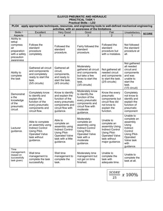
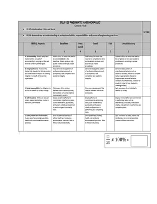
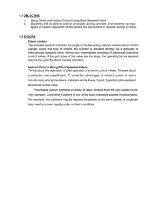
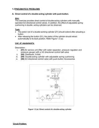
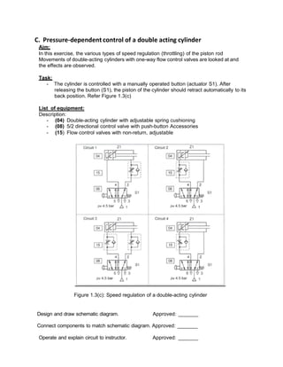
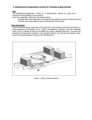
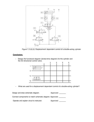
SlideShare a Scribd company logo
1 of 20
Download to read offline
DIPLOMA IN MECHANICAL ENGINEERING (DKM4/DTP4/DEM4/DMB4)
PRACTICAL TASK 1: PNEUMATIC CIRCUIT
COURSE CODE : DJJ5123
COURSE : PNEUMATIC AND HYDRAULIC
NAME : REGISTRATION NO:
DATE : SUBMISSION DATE :
CLASS :
LECTURER :
PREPARED BY:
(PUAN ZUHAILA MOHAMMAD )
CHECKED /
APPROVED BY:
PLO 4
Practical
Task1
PLO 8 Generic Skill:
Professionalism,
Ethics and
Moral
CLO 2 CLO 3
LD 2 LD 8
A A
B B
C C
D D
E E
TOTAL MARKS
(100%)
/25
TOTAL MARKS
(100%)
/25
DJJ5123 PNEUMATIC AND HIDRAULIC
PRACTICAL TASK 1
Practical Skills – LD2
PLO4 apply appropriate techniques, resources, and engineering tools to well-defined mechanical engineering
activities, with an awareness of the limitations
Skills /
Aspects
Excellent Very Good Good Fair Unsatisfactory
SCORE
5 4 3 2 1
Ability to
setup
compress
air
preparation
with a safety
precaution
awareness
Follows the
standard
procedure
completely.
Followed the
standard
procedure.
Fairly followed the
standard
procedure.
Followed the
standard
procedure but
with a mistakes.
Not followed
the standard
procedure at
all.
Ability to
complete
the task
Gathered all circuit
and components
and completely
ready to start the
task.
(5/5 circuits)
Gathered all
circuit,
components,
and ready to
start the task.
(4/5 circuits)
Moderately
gathered all circuit
and components
but take a few
times to start the
task.
(3/5 circuits)
Not gathered all
needed circuit
and components
to start the task.
(2/5 circuits)
Not gathered
all needed
circuit and
components
and was
unable to
start the
task.
(1/5 circuit)
Demonstrat
e the
knowledge
of the
pneumatic
circuit
Completely know
to identify and
explain the
function of the
every pneumatic
components and
circuit flow.
Know to identify
and explain the
function of the
every pneumatic
components and
circuit flow with
guidance.
Moderately know
to identify the
function of the
every pneumatic
components and
circuit flow with
moderate
guidance.
Know the every
pneumatic
components but
circuit flow did
not know to
explain the
function.
Completely
not know to
identify and
explain the
function of
pneumatic
component
Lecturer
guidance.
Able to complete
an assembly using
Indirect Control
Using Pilot-
Operated Valve
task without
guidance.
Able to
complete an
assembly using
Indirect Control
Using Pilot-
Operated Valve
task with a little
guidance.
Moderately
complete an
assembly using
Indirect Control
Using Pilot-
Operated Valve
task with a
moderate
guidance.
Unable to
complete an
assembly Using
Indirect Control
Using Pilot-
Operated Valve
task without
major guidance.
Unable to
complete an
assembly
Using
Indirect
Control
Using Pilot-
Operated
Valve task
with
guidance.
Time
management.
(based on
successfully
task given)
Well time
management to
complete the task
successfully.
Well time
management to
complete the
task.
Moderately time
management but
not get on time
finished.
Unable to
complete the
task with
adequate time.
Unable to
complete the
task at all.
𝑆𝐶𝑂𝑅𝐸
25
𝑥 100%
COURSE LEARNING OUTCOMES (CLO):
Upon completion of this course, students will be able to:
CLO2. Construct accurately pneumatic, electro-pneumatic, electro-hydraulic and
hydraulic circuit according to assigned task. (P4, PLO4)
CLO3. Demonstrate understanding of engineering norm and practices in pneumatics
and Hydraulics during practical work sessions. (A3, PLO8)
SAFETY MEASURES WHEN USING PNEUMATIC CONTROL SYSTEMS
a. Compressed air can cause serious damage to the human body if they enter the body
through ducts like the oral cavity or ears.
b. Never spray compressed air onto anyone.
c. Under high temperature, compressed air can pass through human skin.
d. Compressed air released from the exhaust contains particles and oil droplets, which can
cause damage to eyes.
e. Even though the pressure of compressed air in pipes and reservoirs is relatively low,
when the container loses its entirety, fierce explosions may still occur.
f. Before switching on a compressed air supply unit, one should thoroughly inspect the
whole circuit to see if there are any loose parts, abnormal pressure or damaged pipes.
g. A loose pipe may shake violently due to the high pressure built up inside it. Therefore,
each time before the system pressure is increased; thorough inspection of the entire
circuit is required to prevent accidents.
h. As the force produced by pneumatic cylinders is relatively large, and the action is usually
very fast, you may suffer serious injuries if you get hit by a cylinder.
i. Switches should be installed on the compressed air supply unit to allow easy and speedy
control of air flow.
j. In case of a leakage, the compressed air supply unit should be turned off immediately.
k. The compressed air supply unit must be turned off before changes can be made to the
system.
l. Stay clear of the moving parts of the system. Never try to move the driving parts in the
mechanical operation valve with your hand.
EQUIPMENT REQUIRED
FESTO; Pneumatic Workbench
PROCEDURE
PROCEDURE SUMMARY
In the first part of the exercise, you will verify the status of the trainer by executing the
"trainer status verification procedure".
In the second part of the exercise, you will set up and operate a pneumatic circuit using
the Conditioning Unit, a directional control valve and a cylinder.
Trainer Status Verification Procedure
Each procedure in this manual that requires the use of the Pneumatics Trainer includes
the statement: "Verify the status or the trainer according to the procedure given in
Exercise 1-2". This status verification procedure consists of the following steps:
 Install the work surface on a work table or on a support bench, if any.
 Make sure the work surface is secured to the work table or support bench to ensure
that it will not move or fall down.
 If you use a support bench, make sure the four caster brakes are locked.
 On the Conditioning Unit, close the main shutoff valve by pushing down on the
control button.
 Pull up the regulator adjusting knob to unlock the regulator and turn it completely
counterclockwise.
 Close the four branch shutoff valves of the manifold (collar in the lower position).
Figure 3 shows the Conditioning Unit with shutoff valves.
Figure 1: Conditioning Unit with Branch Shutoff Valves.
Fundamental Pneumatic Circuit
1. Locate the following components:
 Conditioning Unit;
 Directional control valve, 3-way, 2-position, pushbutton-operated;
Note: A directional control valve is a device used to open and close flow paths in a
pneumatic circuit.
 Cylinder, 2.7-cm (or 1 1/16-in) bore, 10-cm (or 4-in) stroke, single acting, and spring
return.
Note: A cylinder is an actuator that converts fluid energy into mechanical energy. Single-
acting cylinders generate force in a single direction.
Figure 2: Schematic Diagram Of A Pneumatics Circuit.
2. Mount the components on the work surface and connect the circuit shown in Figure 4
Refer to the connection diagram shown in Figure 1-21 to make your connections.
Connect the Conditioning Unit to the NC (normally non-passing) port of the directional
control valve.
Figure 3: Connection Diagram of a Pneumatic Circuit.
3. On the Conditioning Unit, open the main shutoff valve and the branch shutoff valve at
the manifold. Screw a tip (bullet) to the rod of the cylinder.
4. Pull up regulator adjusting knob to unlock the regulator and turn it clockwise to set the
pressure at 200 kpa (or 30 psi0 on the regulated Pressure Gauge.
Note: Each time you set the pressure, it is recommended to close and reopen the main shutoff
valve to overcome friction. Readjust the pressure if necessary.
TASK: APPLICATIONS IN PNEUMATIC SYSTEM
1.1 OBJECTIVE
i. Using Direct and Indirect Control Using Pilot-Operated Valve
ii. Students will be able to control of double-acting cylinder, and knowing various
types of speed regulation of the piston rod movement of double-acting cylinder.
1.2 THEORY
Direct control
The simplest level of control for the single or double-acting cylinder involves direct control
signals. Using this type of control, the cylinder is actuated directly via a manually or
mechanically actuated valve, without any intermediate switching of additional directional
control valves. If the port sizes of the valve are too large, the operating forces required
may be too great for direct manual operation.
Indirect Control Using Pilot-Operated Valves
To introduce the operation of pilot-operated directional control valves. To learn about
construction and classification. To show the advantages of indirect control in demo
circuits using a long line device, cylinders and a 4-way, 5-port, 2-position pilot-operated
directional control valve.
Pneumatics system performs a variety of tasks, ranging from the very simple to the
very complex. Controlling cylinders is one of the most important aspects of pneumatics.
For example, two cylinders may be required to operate at the same speed, or a cylinder
may need to extend rapidly under no load conditions.
1.3PNEUMATICS PROBLEMS
A. Direct control of a double-acting cylinder with push-button.
Aim:
This exercise provides direct control of double-acting cylinders with manually
operated 5/2 directional control valves. In addition, the effect of adjustable spring
cushioning in double- acting cylinders can be observed.
Task:
 The piston rod of a double-working cylinder (Z1) should extend after actuating a
button.
 After releasing the button (S1), the piston of the cylinder should retract
automatically to its back position. Refer Figure 1.3 (a).
List of equipment’s:
Description:
i. (01) Air service unit (filter with water separator, pressure regulator and
pressure gauge) with a 3/2 directional control ball valve
ii. (02) Distributor, 6-fold
iii. (04) Double-acting cylinder with adjustable spring cushioning
iv. (08) 5/2 directional control valve with push-button Accessories
Figure 1.3 (a): Direct control of a double-acting cylinder
Circuit Problem:
Using the given components and layout, design a schematic circuit which will
operate one spring return cylinder from any one of three identical valves.
Design and draw schematic diagram. Approved: _______
Connect components to match schematic diagram.Approved: _______
Operate and explain circuit to instructor. Approved: _______
Conclusion:
 The double-acting cylinder can be directly controlled by a ________________________
 In the basic setting (spring position) of a directional valve, port 1 supplied with compressed
air, port 2 is always and port 4 always .
1.3 PNEUMATICS PROBLEMS (continues)
B. Application
Parts are accumulating on a conveyor belt and waiting to be released and transferred to the
next phase of assembly. Technicians at multiple stations need to control the gate release
mechanism to have parts sent to their assembly station.
Objective:
To be able to design and assemble an “OR” logic circuit.
Circuit Problem:
Using the given components and layout, design a schematic circuit which will operate one
spring return cylinder from any one of three identical valves.
Design and draw schematic diagram. Approved: _______
Connect components to match schematic diagram. Approved: _______
Operate and explain circuit to instructor. Approved: _______
Layout of Components Needed:
Part
#
Component Description Qty
1 2-position, spring offset, 3-way valve 3
2 shuttle valve 2
3 push button actuator 3
4 Single acting, spring return cylinder 1
Figure: 1.3 (b)
C. Pressure-dependent control of a double acting cylinder
Aim:
In this exercise, the various types of speed regulation (throttling) of the piston rod
Movements of double-acting cylinders with one-way flow control valves are looked at and
the effects are observed.
Task:
- The cylinder is controlled with a manually operated button (actuator S1). After
releasing the button (S1), the piston of the cylinder should retract automatically to its
back position. Refer Figure 1.3(c)
List of equipment:
Description:
- (04) Double-acting cylinder with adjustable spring cushioning
- (08) 5/2 directional control valve with push-button Accessories
- (15) Flow control valves with non-return, adjustable
Figure 1.3(c): Speed regulation of a double-acting cylinder
Design and draw schematic diagram. Approved: _______
Connect components to match schematic diagram. Approved: _______
Operate and explain circuit to instructor. Approved: _______
Conclusion
Referring to Figure 1.3(c), which circuit demonstrates the following?
a. In Circuit ( ): The speed of the cylinder piston is restricted when
extending.
b. In Circuit ( ): The speed of the cylinder piston is restricted when
retracting.
c. In Circuit ( ): Both speed of the cylinder piston are restricted.
D. Displacement dependent control of a double-acting cylinder
Aim:
The displacement-dependent control of a double-acting cylinder by using limit
switches in demonstrated in this exercise.
Upon the completion of this task, the student will be
• Familiar with indirect actuation of a double acting cylinder by using a double pilot valve.
• Familiar with using different types of directional control valves
Task description:
Using a diverting device, parts are to be moved from one conveyor track onto the other in a
linear sequence as illustrated in Fig. 1.3(d)(i). By operating a selector valve the oscillating
piston rod of a cylinder pushes the turntable via a pawl in stepped sequence. The parts are
diverted and transported onwards in the opposite direction. By returning the selector valve
back to the normal position the drive unit is switched off.
Figure 1.3 (d)(i): Positional sketch
Figure 1.3 (d) (ii): Displacement dependent control of a double-acting cylinder
Conclusion:
- Design the functional diagram (stroke-time diagram) for the cylinder and
the 5/2 directional control valve.
- What are used for a displacement dependent control of a double-acting cylinder?
Design and draw schematic diagram. Approved: _______
Connect components to match schematic diagram. Approved: _______
Operate and explain circuit to instructor. Approved: _______
E. Pressure-dependent control of a double acting cylinder
Aim:
By using a 3/2 directional control valve with adjustable minimum pressure of response, a
pressure dependent control (and in addition displacement dependent) control of a double
acting cylinder is put into effect.
Upon the completion of this task, the student will be
• Familiar with indirect actuation of a double acting cylinder with a double pilot valve.
• Able to use and adjust the pressure sequence valve.
Taskdescription:
A plastic component is embossed using a die driven by a double-acting cylinder. The
die is to advance and emboss the plastic when a push button is operated. The return of
the die is to be effected when a preset pressure is reached. The embossing pressure is
to be adjustable.
Figure 1.3(e): Positional sketch
Task requirements:
1. Draw pneumatic circuit diagram
2. Simulate the circuit using Automation studio software.
3. Assemble the circuit practically and check its operation
List of equipment:
Description:
- (21) Pressure gauge
- (22) 3/2 directional control valve, with adjustable operating pressure
- (13) 3/2 directional control valves, with roller
- (04) Double-acting cylinder with adjustable spring cushioning
- (11) 5/2 directional control valve, impulse valve
- (15) Flow control valves with non-return, adjustable
- (06) 3/2 directional control valve, with manually operated push-button
- (13) 3/2 way roller valve for automatic return of the cylinder.
Figure 1.3(e) (i): Pressure dependent control of a double-acting cylinder
Conclusion:
- Mention the conditions to extend the piston of the cylinder.
- Mention the conditions to retract the piston of the cylinder.
Prepared by: Zuhaila Mohammad
- Design the functional diagram (stroke-time diagram) for the cylinder and the
5/2 directional control valve.
Design and draw schematic diagram. Approved: _______
Connect components to match schematic diagram. Approved: _______
Operate and explain circuit to instructor. Approved: _______
References:
1. https://www.iei.liu.se/flumes/tmms03/filarkiv/lab/1.451122/Lab2_tmms03_PneumaticControlSystems.pdf
2. https://elearning.ju.edu.jo/file.php/14990/Exp._2_Pneumatic_Control_of_a_Double-
acting_Cylinder_2017.pdf
3. Festo Didactics
Prepared by: Zuhaila Mohammad

More Related Content

What's hot

J4012 pneumatik dan hidraulik unit2
J4012 pneumatik dan hidraulik unit2J4012 pneumatik dan hidraulik unit2
J4012 pneumatik dan hidraulik unit2Asraf Malik
 
J4012 pneumatik dan hidraulik unit3
J4012 pneumatik dan hidraulik unit3J4012 pneumatik dan hidraulik unit3
J4012 pneumatik dan hidraulik unit3Asraf Malik
 
J4012 pneumatik dan hidraulik unit7
J4012 pneumatik dan hidraulik unit7J4012 pneumatik dan hidraulik unit7
J4012 pneumatik dan hidraulik unit7Asraf Malik
 
Introduction to electropneumatic
Introduction to electropneumaticIntroduction to electropneumatic
Introduction to electropneumaticAditya Kurniawan
 
J4012 pneumatik dan hidraulik unit11
J4012 pneumatik dan hidraulik unit11J4012 pneumatik dan hidraulik unit11
J4012 pneumatik dan hidraulik unit11Asraf Malik
 
Chapter 1 introduction to pneumatic
Chapter 1 introduction to pneumaticChapter 1 introduction to pneumatic
Chapter 1 introduction to pneumaticTaj Nesha
 
1.sistem litar hidraulik
1.sistem litar hidraulik1.sistem litar hidraulik
1.sistem litar hidraulikEdi Slipknot
 
Pneumatics Circuits Components (Circuit details)
Pneumatics Circuits Components (Circuit details)Pneumatics Circuits Components (Circuit details)
Pneumatics Circuits Components (Circuit details)S K
 
Sistem pneumatik
Sistem pneumatikSistem pneumatik
Sistem pneumatikFendy Endy
 
J4012 pneumatik dan hidraulik unit10
J4012 pneumatik dan hidraulik unit10J4012 pneumatik dan hidraulik unit10
J4012 pneumatik dan hidraulik unit10Asraf Malik
 
penyelenggaraan industri
penyelenggaraan industripenyelenggaraan industri
penyelenggaraan industriJius Musz
 

What's hot (20)

J4012 pneumatik dan hidraulik unit2
J4012 pneumatik dan hidraulik unit2J4012 pneumatik dan hidraulik unit2
J4012 pneumatik dan hidraulik unit2
 
J4012 pneumatik dan hidraulik unit3
J4012 pneumatik dan hidraulik unit3J4012 pneumatik dan hidraulik unit3
J4012 pneumatik dan hidraulik unit3
 
J4012 pneumatik dan hidraulik unit7
J4012 pneumatik dan hidraulik unit7J4012 pneumatik dan hidraulik unit7
J4012 pneumatik dan hidraulik unit7
 
Pneumatic circuits
Pneumatic circuitsPneumatic circuits
Pneumatic circuits
 
Introduction to electropneumatic
Introduction to electropneumaticIntroduction to electropneumatic
Introduction to electropneumatic
 
Hidraulik
HidraulikHidraulik
Hidraulik
 
Kertas penerangan k1
Kertas penerangan k1Kertas penerangan k1
Kertas penerangan k1
 
J4012 pneumatik dan hidraulik unit11
J4012 pneumatik dan hidraulik unit11J4012 pneumatik dan hidraulik unit11
J4012 pneumatik dan hidraulik unit11
 
Chapter 1 introduction to pneumatic
Chapter 1 introduction to pneumaticChapter 1 introduction to pneumatic
Chapter 1 introduction to pneumatic
 
Electrohydraulic
ElectrohydraulicElectrohydraulic
Electrohydraulic
 
Sistem pneumatik
Sistem pneumatikSistem pneumatik
Sistem pneumatik
 
1.sistem litar hidraulik
1.sistem litar hidraulik1.sistem litar hidraulik
1.sistem litar hidraulik
 
Pneumatics Circuits Components (Circuit details)
Pneumatics Circuits Components (Circuit details)Pneumatics Circuits Components (Circuit details)
Pneumatics Circuits Components (Circuit details)
 
Sistem pneumatik
Sistem pneumatikSistem pneumatik
Sistem pneumatik
 
J4012 pneumatik dan hidraulik unit10
J4012 pneumatik dan hidraulik unit10J4012 pneumatik dan hidraulik unit10
J4012 pneumatik dan hidraulik unit10
 
Merombak gearbox manual
Merombak gearbox manual Merombak gearbox manual
Merombak gearbox manual
 
3. switch
3. switch3. switch
3. switch
 
penyelenggaraan industri
penyelenggaraan industripenyelenggaraan industri
penyelenggaraan industri
 
Maintainance
MaintainanceMaintainance
Maintainance
 
11. starter motor
11. starter motor11. starter motor
11. starter motor
 

Similar to Practical task 1 pneumatik june 2018

Instrumentation & Control Lab Manual.pdf
Instrumentation & Control Lab Manual.pdfInstrumentation & Control Lab Manual.pdf
Instrumentation & Control Lab Manual.pdfNTU Faisalabad
 
IRJET- Leakage Testing Machine
IRJET- Leakage Testing MachineIRJET- Leakage Testing Machine
IRJET- Leakage Testing MachineIRJET Journal
 
A Review Paper on Pneumatic Operated Collapsable Steering System
A Review Paper on Pneumatic Operated Collapsable Steering SystemA Review Paper on Pneumatic Operated Collapsable Steering System
A Review Paper on Pneumatic Operated Collapsable Steering SystemIRJET Journal
 
Asco Series 551, 552, 553, Pilot Solenoid Valves, Atex Hazardous Areas - Proc...
Asco Series 551, 552, 553, Pilot Solenoid Valves, Atex Hazardous Areas - Proc...Asco Series 551, 552, 553, Pilot Solenoid Valves, Atex Hazardous Areas - Proc...
Asco Series 551, 552, 553, Pilot Solenoid Valves, Atex Hazardous Areas - Proc...Thorne & Derrick UK
 
171839416-commissioning-of-hydro-ppt.ppt
171839416-commissioning-of-hydro-ppt.ppt171839416-commissioning-of-hydro-ppt.ppt
171839416-commissioning-of-hydro-ppt.pptssuser9e9be71
 
Working elements of Pneumatic System with Circuits, Safety, Installation
Working elements of Pneumatic System with Circuits, Safety, InstallationWorking elements of Pneumatic System with Circuits, Safety, Installation
Working elements of Pneumatic System with Circuits, Safety, InstallationMohammad Azam Khan
 
Basic hydraulic systems
Basic hydraulic systemsBasic hydraulic systems
Basic hydraulic systemsHong Giang
 
Compressor fundamentals
Compressor fundamentalsCompressor fundamentals
Compressor fundamentalsPrem Baboo
 
FABRICATION OF PNEUMATIC CONTROLLED RAMMER STRIKER FOR MOULDING PROCES.pptx
FABRICATION  OF  PNEUMATIC CONTROLLED RAMMER STRIKER FOR MOULDING PROCES.pptxFABRICATION  OF  PNEUMATIC CONTROLLED RAMMER STRIKER FOR MOULDING PROCES.pptx
FABRICATION OF PNEUMATIC CONTROLLED RAMMER STRIKER FOR MOULDING PROCES.pptxchockalingam athilingam
 
Single action cylinder
Single action cylinderSingle action cylinder
Single action cylinderrawaabdullah
 
Hyster b214 (h450 hds ec) forklift service repair manual
Hyster b214 (h450 hds ec) forklift service repair manualHyster b214 (h450 hds ec) forklift service repair manual
Hyster b214 (h450 hds ec) forklift service repair manualuufdjjjskkemm
 
Hyster b214 (h500 hd ec) forklift service repair manual
Hyster b214 (h500 hd ec) forklift service repair manualHyster b214 (h500 hd ec) forklift service repair manual
Hyster b214 (h500 hd ec) forklift service repair manualufjkskemfseol
 
Hyster b214 (h450 hds ec) forklift service repair manual
Hyster b214 (h450 hds ec) forklift service repair manualHyster b214 (h450 hds ec) forklift service repair manual
Hyster b214 (h450 hds ec) forklift service repair manualfujsjefkskem
 
Hyster b214 (h500 hd ec) forklift service repair manual
Hyster b214 (h500 hd ec) forklift service repair manualHyster b214 (h500 hd ec) forklift service repair manual
Hyster b214 (h500 hd ec) forklift service repair manualfhjsekfksemert
 
Hyster b214 (h450 hds ec) forklift service repair manual
Hyster b214 (h450 hds ec) forklift service repair manualHyster b214 (h450 hds ec) forklift service repair manual
Hyster b214 (h450 hds ec) forklift service repair manualfjkskmmdmme
 

Similar to Practical task 1 pneumatik june 2018 (20)

Instrumentation & Control Lab Manual.pdf
Instrumentation & Control Lab Manual.pdfInstrumentation & Control Lab Manual.pdf
Instrumentation & Control Lab Manual.pdf
 
mn03010.pdf
mn03010.pdfmn03010.pdf
mn03010.pdf
 
IRJET- Leakage Testing Machine
IRJET- Leakage Testing MachineIRJET- Leakage Testing Machine
IRJET- Leakage Testing Machine
 
A Review Paper on Pneumatic Operated Collapsable Steering System
A Review Paper on Pneumatic Operated Collapsable Steering SystemA Review Paper on Pneumatic Operated Collapsable Steering System
A Review Paper on Pneumatic Operated Collapsable Steering System
 
Fab gearshift 2012
Fab gearshift 2012Fab gearshift 2012
Fab gearshift 2012
 
Asco Series 551, 552, 553, Pilot Solenoid Valves, Atex Hazardous Areas - Proc...
Asco Series 551, 552, 553, Pilot Solenoid Valves, Atex Hazardous Areas - Proc...Asco Series 551, 552, 553, Pilot Solenoid Valves, Atex Hazardous Areas - Proc...
Asco Series 551, 552, 553, Pilot Solenoid Valves, Atex Hazardous Areas - Proc...
 
Pneumatic conveyor snpt2012
Pneumatic conveyor  snpt2012Pneumatic conveyor  snpt2012
Pneumatic conveyor snpt2012
 
Hst ppt
Hst pptHst ppt
Hst ppt
 
171839416-commissioning-of-hydro-ppt.ppt
171839416-commissioning-of-hydro-ppt.ppt171839416-commissioning-of-hydro-ppt.ppt
171839416-commissioning-of-hydro-ppt.ppt
 
Working elements of Pneumatic System with Circuits, Safety, Installation
Working elements of Pneumatic System with Circuits, Safety, InstallationWorking elements of Pneumatic System with Circuits, Safety, Installation
Working elements of Pneumatic System with Circuits, Safety, Installation
 
Basic hydraulic systems
Basic hydraulic systemsBasic hydraulic systems
Basic hydraulic systems
 
Compressor fundamentals
Compressor fundamentalsCompressor fundamentals
Compressor fundamentals
 
Fmp 8000 manual
Fmp 8000 manualFmp 8000 manual
Fmp 8000 manual
 
FABRICATION OF PNEUMATIC CONTROLLED RAMMER STRIKER FOR MOULDING PROCES.pptx
FABRICATION  OF  PNEUMATIC CONTROLLED RAMMER STRIKER FOR MOULDING PROCES.pptxFABRICATION  OF  PNEUMATIC CONTROLLED RAMMER STRIKER FOR MOULDING PROCES.pptx
FABRICATION OF PNEUMATIC CONTROLLED RAMMER STRIKER FOR MOULDING PROCES.pptx
 
Single action cylinder
Single action cylinderSingle action cylinder
Single action cylinder
 
Hyster b214 (h450 hds ec) forklift service repair manual
Hyster b214 (h450 hds ec) forklift service repair manualHyster b214 (h450 hds ec) forklift service repair manual
Hyster b214 (h450 hds ec) forklift service repair manual
 
Hyster b214 (h500 hd ec) forklift service repair manual
Hyster b214 (h500 hd ec) forklift service repair manualHyster b214 (h500 hd ec) forklift service repair manual
Hyster b214 (h500 hd ec) forklift service repair manual
 
Hyster b214 (h450 hds ec) forklift service repair manual
Hyster b214 (h450 hds ec) forklift service repair manualHyster b214 (h450 hds ec) forklift service repair manual
Hyster b214 (h450 hds ec) forklift service repair manual
 

Recently uploaded

APPLICATIONS-AC/DC DRIVES-OPERATING CHARACTERISTICS
APPLICATIONS-AC/DC DRIVES-OPERATING CHARACTERISTICSAPPLICATIONS-AC/DC DRIVES-OPERATING CHARACTERISTICS
APPLICATIONS-AC/DC DRIVES-OPERATING CHARACTERISTICSKurinjimalarL3
 
(SHREYA) Chakan Call Girls Just Call 7001035870 [ Cash on Delivery ] Pune Esc...
(SHREYA) Chakan Call Girls Just Call 7001035870 [ Cash on Delivery ] Pune Esc...(SHREYA) Chakan Call Girls Just Call 7001035870 [ Cash on Delivery ] Pune Esc...
(SHREYA) Chakan Call Girls Just Call 7001035870 [ Cash on Delivery ] Pune Esc...ranjana rawat
 
Gfe Mayur Vihar Call Girls Service WhatsApp -> 9999965857 Available 24x7 ^ De...
Gfe Mayur Vihar Call Girls Service WhatsApp -> 9999965857 Available 24x7 ^ De...Gfe Mayur Vihar Call Girls Service WhatsApp -> 9999965857 Available 24x7 ^ De...
Gfe Mayur Vihar Call Girls Service WhatsApp -> 9999965857 Available 24x7 ^ De...srsj9000
 
HARMONY IN THE NATURE AND EXISTENCE - Unit-IV
HARMONY IN THE NATURE AND EXISTENCE - Unit-IVHARMONY IN THE NATURE AND EXISTENCE - Unit-IV
HARMONY IN THE NATURE AND EXISTENCE - Unit-IVRajaP95
 
College Call Girls Nashik Nehal 7001305949 Independent Escort Service Nashik
College Call Girls Nashik Nehal 7001305949 Independent Escort Service NashikCollege Call Girls Nashik Nehal 7001305949 Independent Escort Service Nashik
College Call Girls Nashik Nehal 7001305949 Independent Escort Service NashikCall Girls in Nagpur High Profile
 
Introduction to IEEE STANDARDS and its different types.pptx
Introduction to IEEE STANDARDS and its different types.pptxIntroduction to IEEE STANDARDS and its different types.pptx
Introduction to IEEE STANDARDS and its different types.pptxupamatechverse
 
HARDNESS, FRACTURE TOUGHNESS AND STRENGTH OF CERAMICS
HARDNESS, FRACTURE TOUGHNESS AND STRENGTH OF CERAMICSHARDNESS, FRACTURE TOUGHNESS AND STRENGTH OF CERAMICS
HARDNESS, FRACTURE TOUGHNESS AND STRENGTH OF CERAMICSRajkumarAkumalla
 
MANUFACTURING PROCESS-II UNIT-2 LATHE MACHINE
MANUFACTURING PROCESS-II UNIT-2 LATHE MACHINEMANUFACTURING PROCESS-II UNIT-2 LATHE MACHINE
MANUFACTURING PROCESS-II UNIT-2 LATHE MACHINESIVASHANKAR N
 
Structural Analysis and Design of Foundations: A Comprehensive Handbook for S...
Structural Analysis and Design of Foundations: A Comprehensive Handbook for S...Structural Analysis and Design of Foundations: A Comprehensive Handbook for S...
Structural Analysis and Design of Foundations: A Comprehensive Handbook for S...Dr.Costas Sachpazis
 
(ANVI) Koregaon Park Call Girls Just Call 7001035870 [ Cash on Delivery ] Pun...
(ANVI) Koregaon Park Call Girls Just Call 7001035870 [ Cash on Delivery ] Pun...(ANVI) Koregaon Park Call Girls Just Call 7001035870 [ Cash on Delivery ] Pun...
(ANVI) Koregaon Park Call Girls Just Call 7001035870 [ Cash on Delivery ] Pun...ranjana rawat
 
chaitra-1.pptx fake news detection using machine learning
chaitra-1.pptx  fake news detection using machine learningchaitra-1.pptx  fake news detection using machine learning
chaitra-1.pptx fake news detection using machine learningmisbanausheenparvam
 
Extrusion Processes and Their Limitations
Extrusion Processes and Their LimitationsExtrusion Processes and Their Limitations
Extrusion Processes and Their Limitations120cr0395
 
Call for Papers - African Journal of Biological Sciences, E-ISSN: 2663-2187, ...
Call for Papers - African Journal of Biological Sciences, E-ISSN: 2663-2187, ...Call for Papers - African Journal of Biological Sciences, E-ISSN: 2663-2187, ...
Call for Papers - African Journal of Biological Sciences, E-ISSN: 2663-2187, ...Christo Ananth
 
Porous Ceramics seminar and technical writing
Porous Ceramics seminar and technical writingPorous Ceramics seminar and technical writing
Porous Ceramics seminar and technical writingrakeshbaidya232001
 
(ANJALI) Dange Chowk Call Girls Just Call 7001035870 [ Cash on Delivery ] Pun...
(ANJALI) Dange Chowk Call Girls Just Call 7001035870 [ Cash on Delivery ] Pun...(ANJALI) Dange Chowk Call Girls Just Call 7001035870 [ Cash on Delivery ] Pun...
(ANJALI) Dange Chowk Call Girls Just Call 7001035870 [ Cash on Delivery ] Pun...ranjana rawat
 
MANUFACTURING PROCESS-II UNIT-5 NC MACHINE TOOLS
MANUFACTURING PROCESS-II UNIT-5 NC MACHINE TOOLSMANUFACTURING PROCESS-II UNIT-5 NC MACHINE TOOLS
MANUFACTURING PROCESS-II UNIT-5 NC MACHINE TOOLSSIVASHANKAR N
 
Software Development Life Cycle By Team Orange (Dept. of Pharmacy)
Software Development Life Cycle By  Team Orange (Dept. of Pharmacy)Software Development Life Cycle By  Team Orange (Dept. of Pharmacy)
Software Development Life Cycle By Team Orange (Dept. of Pharmacy)Suman Mia
 
Call Girls Delhi {Jodhpur} 9711199012 high profile service
Call Girls Delhi {Jodhpur} 9711199012 high profile serviceCall Girls Delhi {Jodhpur} 9711199012 high profile service
Call Girls Delhi {Jodhpur} 9711199012 high profile servicerehmti665
 
SPICE PARK APR2024 ( 6,793 SPICE Models )
SPICE PARK APR2024 ( 6,793 SPICE Models )SPICE PARK APR2024 ( 6,793 SPICE Models )
SPICE PARK APR2024 ( 6,793 SPICE Models )Tsuyoshi Horigome
 

Recently uploaded (20)

APPLICATIONS-AC/DC DRIVES-OPERATING CHARACTERISTICS
APPLICATIONS-AC/DC DRIVES-OPERATING CHARACTERISTICSAPPLICATIONS-AC/DC DRIVES-OPERATING CHARACTERISTICS
APPLICATIONS-AC/DC DRIVES-OPERATING CHARACTERISTICS
 
(SHREYA) Chakan Call Girls Just Call 7001035870 [ Cash on Delivery ] Pune Esc...
(SHREYA) Chakan Call Girls Just Call 7001035870 [ Cash on Delivery ] Pune Esc...(SHREYA) Chakan Call Girls Just Call 7001035870 [ Cash on Delivery ] Pune Esc...
(SHREYA) Chakan Call Girls Just Call 7001035870 [ Cash on Delivery ] Pune Esc...
 
Gfe Mayur Vihar Call Girls Service WhatsApp -> 9999965857 Available 24x7 ^ De...
Gfe Mayur Vihar Call Girls Service WhatsApp -> 9999965857 Available 24x7 ^ De...Gfe Mayur Vihar Call Girls Service WhatsApp -> 9999965857 Available 24x7 ^ De...
Gfe Mayur Vihar Call Girls Service WhatsApp -> 9999965857 Available 24x7 ^ De...
 
HARMONY IN THE NATURE AND EXISTENCE - Unit-IV
HARMONY IN THE NATURE AND EXISTENCE - Unit-IVHARMONY IN THE NATURE AND EXISTENCE - Unit-IV
HARMONY IN THE NATURE AND EXISTENCE - Unit-IV
 
College Call Girls Nashik Nehal 7001305949 Independent Escort Service Nashik
College Call Girls Nashik Nehal 7001305949 Independent Escort Service NashikCollege Call Girls Nashik Nehal 7001305949 Independent Escort Service Nashik
College Call Girls Nashik Nehal 7001305949 Independent Escort Service Nashik
 
Introduction to IEEE STANDARDS and its different types.pptx
Introduction to IEEE STANDARDS and its different types.pptxIntroduction to IEEE STANDARDS and its different types.pptx
Introduction to IEEE STANDARDS and its different types.pptx
 
HARDNESS, FRACTURE TOUGHNESS AND STRENGTH OF CERAMICS
HARDNESS, FRACTURE TOUGHNESS AND STRENGTH OF CERAMICSHARDNESS, FRACTURE TOUGHNESS AND STRENGTH OF CERAMICS
HARDNESS, FRACTURE TOUGHNESS AND STRENGTH OF CERAMICS
 
MANUFACTURING PROCESS-II UNIT-2 LATHE MACHINE
MANUFACTURING PROCESS-II UNIT-2 LATHE MACHINEMANUFACTURING PROCESS-II UNIT-2 LATHE MACHINE
MANUFACTURING PROCESS-II UNIT-2 LATHE MACHINE
 
Structural Analysis and Design of Foundations: A Comprehensive Handbook for S...
Structural Analysis and Design of Foundations: A Comprehensive Handbook for S...Structural Analysis and Design of Foundations: A Comprehensive Handbook for S...
Structural Analysis and Design of Foundations: A Comprehensive Handbook for S...
 
(ANVI) Koregaon Park Call Girls Just Call 7001035870 [ Cash on Delivery ] Pun...
(ANVI) Koregaon Park Call Girls Just Call 7001035870 [ Cash on Delivery ] Pun...(ANVI) Koregaon Park Call Girls Just Call 7001035870 [ Cash on Delivery ] Pun...
(ANVI) Koregaon Park Call Girls Just Call 7001035870 [ Cash on Delivery ] Pun...
 
Exploring_Network_Security_with_JA3_by_Rakesh Seal.pptx
Exploring_Network_Security_with_JA3_by_Rakesh Seal.pptxExploring_Network_Security_with_JA3_by_Rakesh Seal.pptx
Exploring_Network_Security_with_JA3_by_Rakesh Seal.pptx
 
chaitra-1.pptx fake news detection using machine learning
chaitra-1.pptx  fake news detection using machine learningchaitra-1.pptx  fake news detection using machine learning
chaitra-1.pptx fake news detection using machine learning
 
Extrusion Processes and Their Limitations
Extrusion Processes and Their LimitationsExtrusion Processes and Their Limitations
Extrusion Processes and Their Limitations
 
Call for Papers - African Journal of Biological Sciences, E-ISSN: 2663-2187, ...
Call for Papers - African Journal of Biological Sciences, E-ISSN: 2663-2187, ...Call for Papers - African Journal of Biological Sciences, E-ISSN: 2663-2187, ...
Call for Papers - African Journal of Biological Sciences, E-ISSN: 2663-2187, ...
 
Porous Ceramics seminar and technical writing
Porous Ceramics seminar and technical writingPorous Ceramics seminar and technical writing
Porous Ceramics seminar and technical writing
 
(ANJALI) Dange Chowk Call Girls Just Call 7001035870 [ Cash on Delivery ] Pun...
(ANJALI) Dange Chowk Call Girls Just Call 7001035870 [ Cash on Delivery ] Pun...(ANJALI) Dange Chowk Call Girls Just Call 7001035870 [ Cash on Delivery ] Pun...
(ANJALI) Dange Chowk Call Girls Just Call 7001035870 [ Cash on Delivery ] Pun...
 
MANUFACTURING PROCESS-II UNIT-5 NC MACHINE TOOLS
MANUFACTURING PROCESS-II UNIT-5 NC MACHINE TOOLSMANUFACTURING PROCESS-II UNIT-5 NC MACHINE TOOLS
MANUFACTURING PROCESS-II UNIT-5 NC MACHINE TOOLS
 
Software Development Life Cycle By Team Orange (Dept. of Pharmacy)
Software Development Life Cycle By  Team Orange (Dept. of Pharmacy)Software Development Life Cycle By  Team Orange (Dept. of Pharmacy)
Software Development Life Cycle By Team Orange (Dept. of Pharmacy)
 
Call Girls Delhi {Jodhpur} 9711199012 high profile service
Call Girls Delhi {Jodhpur} 9711199012 high profile serviceCall Girls Delhi {Jodhpur} 9711199012 high profile service
Call Girls Delhi {Jodhpur} 9711199012 high profile service
 
SPICE PARK APR2024 ( 6,793 SPICE Models )
SPICE PARK APR2024 ( 6,793 SPICE Models )SPICE PARK APR2024 ( 6,793 SPICE Models )
SPICE PARK APR2024 ( 6,793 SPICE Models )
 

Practical task 1 pneumatik june 2018

  • 1. DIPLOMA IN MECHANICAL ENGINEERING (DKM4/DTP4/DEM4/DMB4) PRACTICAL TASK 1: PNEUMATIC CIRCUIT COURSE CODE : DJJ5123 COURSE : PNEUMATIC AND HYDRAULIC NAME : REGISTRATION NO: DATE : SUBMISSION DATE : CLASS : LECTURER : PREPARED BY: (PUAN ZUHAILA MOHAMMAD ) CHECKED / APPROVED BY: PLO 4 Practical Task1 PLO 8 Generic Skill: Professionalism, Ethics and Moral CLO 2 CLO 3 LD 2 LD 8 A A B B C C D D E E TOTAL MARKS (100%) /25 TOTAL MARKS (100%) /25
  • 2. DJJ5123 PNEUMATIC AND HIDRAULIC PRACTICAL TASK 1 Practical Skills – LD2 PLO4 apply appropriate techniques, resources, and engineering tools to well-defined mechanical engineering activities, with an awareness of the limitations Skills / Aspects Excellent Very Good Good Fair Unsatisfactory SCORE 5 4 3 2 1 Ability to setup compress air preparation with a safety precaution awareness Follows the standard procedure completely. Followed the standard procedure. Fairly followed the standard procedure. Followed the standard procedure but with a mistakes. Not followed the standard procedure at all. Ability to complete the task Gathered all circuit and components and completely ready to start the task. (5/5 circuits) Gathered all circuit, components, and ready to start the task. (4/5 circuits) Moderately gathered all circuit and components but take a few times to start the task. (3/5 circuits) Not gathered all needed circuit and components to start the task. (2/5 circuits) Not gathered all needed circuit and components and was unable to start the task. (1/5 circuit) Demonstrat e the knowledge of the pneumatic circuit Completely know to identify and explain the function of the every pneumatic components and circuit flow. Know to identify and explain the function of the every pneumatic components and circuit flow with guidance. Moderately know to identify the function of the every pneumatic components and circuit flow with moderate guidance. Know the every pneumatic components but circuit flow did not know to explain the function. Completely not know to identify and explain the function of pneumatic component Lecturer guidance. Able to complete an assembly using Indirect Control Using Pilot- Operated Valve task without guidance. Able to complete an assembly using Indirect Control Using Pilot- Operated Valve task with a little guidance. Moderately complete an assembly using Indirect Control Using Pilot- Operated Valve task with a moderate guidance. Unable to complete an assembly Using Indirect Control Using Pilot- Operated Valve task without major guidance. Unable to complete an assembly Using Indirect Control Using Pilot- Operated Valve task with guidance. Time management. (based on successfully task given) Well time management to complete the task successfully. Well time management to complete the task. Moderately time management but not get on time finished. Unable to complete the task with adequate time. Unable to complete the task at all. 𝑆𝐶𝑂𝑅𝐸 25 𝑥 100%
  • 3.
  • 4. COURSE LEARNING OUTCOMES (CLO): Upon completion of this course, students will be able to: CLO2. Construct accurately pneumatic, electro-pneumatic, electro-hydraulic and hydraulic circuit according to assigned task. (P4, PLO4) CLO3. Demonstrate understanding of engineering norm and practices in pneumatics and Hydraulics during practical work sessions. (A3, PLO8) SAFETY MEASURES WHEN USING PNEUMATIC CONTROL SYSTEMS
  • 5. a. Compressed air can cause serious damage to the human body if they enter the body through ducts like the oral cavity or ears. b. Never spray compressed air onto anyone. c. Under high temperature, compressed air can pass through human skin. d. Compressed air released from the exhaust contains particles and oil droplets, which can cause damage to eyes. e. Even though the pressure of compressed air in pipes and reservoirs is relatively low, when the container loses its entirety, fierce explosions may still occur. f. Before switching on a compressed air supply unit, one should thoroughly inspect the whole circuit to see if there are any loose parts, abnormal pressure or damaged pipes. g. A loose pipe may shake violently due to the high pressure built up inside it. Therefore, each time before the system pressure is increased; thorough inspection of the entire circuit is required to prevent accidents. h. As the force produced by pneumatic cylinders is relatively large, and the action is usually very fast, you may suffer serious injuries if you get hit by a cylinder. i. Switches should be installed on the compressed air supply unit to allow easy and speedy control of air flow. j. In case of a leakage, the compressed air supply unit should be turned off immediately. k. The compressed air supply unit must be turned off before changes can be made to the system. l. Stay clear of the moving parts of the system. Never try to move the driving parts in the mechanical operation valve with your hand. EQUIPMENT REQUIRED FESTO; Pneumatic Workbench PROCEDURE
  • 6. PROCEDURE SUMMARY In the first part of the exercise, you will verify the status of the trainer by executing the "trainer status verification procedure". In the second part of the exercise, you will set up and operate a pneumatic circuit using the Conditioning Unit, a directional control valve and a cylinder. Trainer Status Verification Procedure Each procedure in this manual that requires the use of the Pneumatics Trainer includes the statement: "Verify the status or the trainer according to the procedure given in Exercise 1-2". This status verification procedure consists of the following steps:  Install the work surface on a work table or on a support bench, if any.  Make sure the work surface is secured to the work table or support bench to ensure that it will not move or fall down.  If you use a support bench, make sure the four caster brakes are locked.  On the Conditioning Unit, close the main shutoff valve by pushing down on the control button.  Pull up the regulator adjusting knob to unlock the regulator and turn it completely counterclockwise.  Close the four branch shutoff valves of the manifold (collar in the lower position). Figure 3 shows the Conditioning Unit with shutoff valves. Figure 1: Conditioning Unit with Branch Shutoff Valves. Fundamental Pneumatic Circuit
  • 7. 1. Locate the following components:  Conditioning Unit;  Directional control valve, 3-way, 2-position, pushbutton-operated; Note: A directional control valve is a device used to open and close flow paths in a pneumatic circuit.  Cylinder, 2.7-cm (or 1 1/16-in) bore, 10-cm (or 4-in) stroke, single acting, and spring return. Note: A cylinder is an actuator that converts fluid energy into mechanical energy. Single- acting cylinders generate force in a single direction. Figure 2: Schematic Diagram Of A Pneumatics Circuit. 2. Mount the components on the work surface and connect the circuit shown in Figure 4 Refer to the connection diagram shown in Figure 1-21 to make your connections. Connect the Conditioning Unit to the NC (normally non-passing) port of the directional control valve. Figure 3: Connection Diagram of a Pneumatic Circuit. 3. On the Conditioning Unit, open the main shutoff valve and the branch shutoff valve at the manifold. Screw a tip (bullet) to the rod of the cylinder.
  • 8. 4. Pull up regulator adjusting knob to unlock the regulator and turn it clockwise to set the pressure at 200 kpa (or 30 psi0 on the regulated Pressure Gauge. Note: Each time you set the pressure, it is recommended to close and reopen the main shutoff valve to overcome friction. Readjust the pressure if necessary. TASK: APPLICATIONS IN PNEUMATIC SYSTEM
  • 9. 1.1 OBJECTIVE i. Using Direct and Indirect Control Using Pilot-Operated Valve ii. Students will be able to control of double-acting cylinder, and knowing various types of speed regulation of the piston rod movement of double-acting cylinder. 1.2 THEORY Direct control The simplest level of control for the single or double-acting cylinder involves direct control signals. Using this type of control, the cylinder is actuated directly via a manually or mechanically actuated valve, without any intermediate switching of additional directional control valves. If the port sizes of the valve are too large, the operating forces required may be too great for direct manual operation. Indirect Control Using Pilot-Operated Valves To introduce the operation of pilot-operated directional control valves. To learn about construction and classification. To show the advantages of indirect control in demo circuits using a long line device, cylinders and a 4-way, 5-port, 2-position pilot-operated directional control valve. Pneumatics system performs a variety of tasks, ranging from the very simple to the very complex. Controlling cylinders is one of the most important aspects of pneumatics. For example, two cylinders may be required to operate at the same speed, or a cylinder may need to extend rapidly under no load conditions.
  • 10. 1.3PNEUMATICS PROBLEMS A. Direct control of a double-acting cylinder with push-button. Aim: This exercise provides direct control of double-acting cylinders with manually operated 5/2 directional control valves. In addition, the effect of adjustable spring cushioning in double- acting cylinders can be observed. Task:  The piston rod of a double-working cylinder (Z1) should extend after actuating a button.  After releasing the button (S1), the piston of the cylinder should retract automatically to its back position. Refer Figure 1.3 (a). List of equipment’s: Description: i. (01) Air service unit (filter with water separator, pressure regulator and pressure gauge) with a 3/2 directional control ball valve ii. (02) Distributor, 6-fold iii. (04) Double-acting cylinder with adjustable spring cushioning iv. (08) 5/2 directional control valve with push-button Accessories Figure 1.3 (a): Direct control of a double-acting cylinder Circuit Problem:
  • 11. Using the given components and layout, design a schematic circuit which will operate one spring return cylinder from any one of three identical valves. Design and draw schematic diagram. Approved: _______ Connect components to match schematic diagram.Approved: _______ Operate and explain circuit to instructor. Approved: _______ Conclusion:  The double-acting cylinder can be directly controlled by a ________________________  In the basic setting (spring position) of a directional valve, port 1 supplied with compressed air, port 2 is always and port 4 always .
  • 12. 1.3 PNEUMATICS PROBLEMS (continues) B. Application Parts are accumulating on a conveyor belt and waiting to be released and transferred to the next phase of assembly. Technicians at multiple stations need to control the gate release mechanism to have parts sent to their assembly station. Objective: To be able to design and assemble an “OR” logic circuit. Circuit Problem: Using the given components and layout, design a schematic circuit which will operate one spring return cylinder from any one of three identical valves. Design and draw schematic diagram. Approved: _______ Connect components to match schematic diagram. Approved: _______ Operate and explain circuit to instructor. Approved: _______ Layout of Components Needed: Part # Component Description Qty 1 2-position, spring offset, 3-way valve 3 2 shuttle valve 2 3 push button actuator 3 4 Single acting, spring return cylinder 1 Figure: 1.3 (b)
  • 13. C. Pressure-dependent control of a double acting cylinder Aim: In this exercise, the various types of speed regulation (throttling) of the piston rod Movements of double-acting cylinders with one-way flow control valves are looked at and the effects are observed. Task: - The cylinder is controlled with a manually operated button (actuator S1). After releasing the button (S1), the piston of the cylinder should retract automatically to its back position. Refer Figure 1.3(c) List of equipment: Description: - (04) Double-acting cylinder with adjustable spring cushioning - (08) 5/2 directional control valve with push-button Accessories - (15) Flow control valves with non-return, adjustable Figure 1.3(c): Speed regulation of a double-acting cylinder Design and draw schematic diagram. Approved: _______ Connect components to match schematic diagram. Approved: _______ Operate and explain circuit to instructor. Approved: _______
  • 14. Conclusion Referring to Figure 1.3(c), which circuit demonstrates the following? a. In Circuit ( ): The speed of the cylinder piston is restricted when extending. b. In Circuit ( ): The speed of the cylinder piston is restricted when retracting. c. In Circuit ( ): Both speed of the cylinder piston are restricted.
  • 15. D. Displacement dependent control of a double-acting cylinder Aim: The displacement-dependent control of a double-acting cylinder by using limit switches in demonstrated in this exercise. Upon the completion of this task, the student will be • Familiar with indirect actuation of a double acting cylinder by using a double pilot valve. • Familiar with using different types of directional control valves Task description: Using a diverting device, parts are to be moved from one conveyor track onto the other in a linear sequence as illustrated in Fig. 1.3(d)(i). By operating a selector valve the oscillating piston rod of a cylinder pushes the turntable via a pawl in stepped sequence. The parts are diverted and transported onwards in the opposite direction. By returning the selector valve back to the normal position the drive unit is switched off. Figure 1.3 (d)(i): Positional sketch
  • 16. Figure 1.3 (d) (ii): Displacement dependent control of a double-acting cylinder Conclusion: - Design the functional diagram (stroke-time diagram) for the cylinder and the 5/2 directional control valve. - What are used for a displacement dependent control of a double-acting cylinder? Design and draw schematic diagram. Approved: _______ Connect components to match schematic diagram. Approved: _______ Operate and explain circuit to instructor. Approved: _______
  • 17. E. Pressure-dependent control of a double acting cylinder Aim: By using a 3/2 directional control valve with adjustable minimum pressure of response, a pressure dependent control (and in addition displacement dependent) control of a double acting cylinder is put into effect. Upon the completion of this task, the student will be • Familiar with indirect actuation of a double acting cylinder with a double pilot valve. • Able to use and adjust the pressure sequence valve. Taskdescription: A plastic component is embossed using a die driven by a double-acting cylinder. The die is to advance and emboss the plastic when a push button is operated. The return of the die is to be effected when a preset pressure is reached. The embossing pressure is to be adjustable. Figure 1.3(e): Positional sketch Task requirements: 1. Draw pneumatic circuit diagram 2. Simulate the circuit using Automation studio software. 3. Assemble the circuit practically and check its operation List of equipment: Description: - (21) Pressure gauge - (22) 3/2 directional control valve, with adjustable operating pressure - (13) 3/2 directional control valves, with roller - (04) Double-acting cylinder with adjustable spring cushioning - (11) 5/2 directional control valve, impulse valve - (15) Flow control valves with non-return, adjustable - (06) 3/2 directional control valve, with manually operated push-button - (13) 3/2 way roller valve for automatic return of the cylinder.
  • 18. Figure 1.3(e) (i): Pressure dependent control of a double-acting cylinder Conclusion: - Mention the conditions to extend the piston of the cylinder. - Mention the conditions to retract the piston of the cylinder.
  • 19. Prepared by: Zuhaila Mohammad - Design the functional diagram (stroke-time diagram) for the cylinder and the 5/2 directional control valve. Design and draw schematic diagram. Approved: _______ Connect components to match schematic diagram. Approved: _______ Operate and explain circuit to instructor. Approved: _______ References: 1. https://www.iei.liu.se/flumes/tmms03/filarkiv/lab/1.451122/Lab2_tmms03_PneumaticControlSystems.pdf 2. https://elearning.ju.edu.jo/file.php/14990/Exp._2_Pneumatic_Control_of_a_Double- acting_Cylinder_2017.pdf 3. Festo Didactics