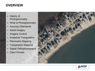
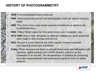
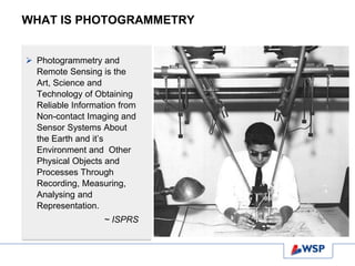
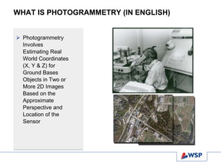
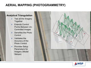
Photogrammetry 101
Ted Covill, CP, PPS
NEARC Spring 2015 Conference
May 11, 2015
OVERVIEW
 History of
Photogrammetry
 What is Photogrammetry
 Accuracy Standards
 Aerial Imagery
 Imagery Control
 Analytical Triangulation
 Planimetric Mapping
 Topographic Mapping
 Digital Orthophotography
 Data Formats
HISTORY OF PHOTOGRAMMETRY
 1839: First photographs were produced
 1849: Aime Laussedat proved that photography could be used to produce
maps
 1862: The Union Army used aerial cameras on balloons to observe the
Confederate Army
 1909: Wilbur Wright takes the first aerial photo over Centocelli, Italy
 1914-1945: Due to high demands on defense intelligence, great advances
were made in both Europe and the US
 1942: Bausch & Lomb became the chief supplier of aerial cameras
and mapping equipment worldwide
 Today: Photo missions are flown by aircraft (fixed wing and helicopter) with
cameras, digital sensors and LiDAR sensors attached to the
underside of an aircraft. The development of systems for producing
accurate measurements has continued to advance from an aerial
platform.
WHAT IS PHOTOGRAMMETRY
 Photogrammetry and
Remote Sensing is the
Art, Science and
Technology of Obtaining
Reliable Information from
Non-contact Imaging and
Sensor Systems About
the Earth and it’s
Environment and Other
Physical Objects and
Processes Through
Recording, Measuring,
Analysing and
Representation.
~ ISPRS
WHAT IS PHOTOGRAMMETRY (IN ENGLISH)
 Photogrammetry
Involves
Estimating Real
World Coordinates
(X, Y & Z) for
Ground Bases
Objects in Two or
More 2D Images
Based on the
Approximate
Perspective and
Location of the
Sensor
ACCURACY STANDARDS
 National Map
Accuracy
Standards
(NMAS)
 American Society
of
Photogrammetry
& Remote
Sensing (ASPRS)
Accuracy
Standards
PROJECT PLANNING
 Define Project
Area
 Define the
Accuracy
Specification,
Both Horizontal
and Vertical
 Determine
Control
Location
Requirements
 Targets vs.
Photo ID
 Will Airborne
GPS (AbGPS)
be used
AERIAL IMAGERY
Aerial Imagery:
 Fixed Wing or
Helicopter
 Traditional Film (Color
& BW) or Digital (Color
& Infrared)
 Stereo Coverage (60%
Forward Overlap/ 30%
Side Overlap)
 Fly at the Proper
Altitude to Insure
Accuracy
 Fall/Spring Flying
Season (Leaf-off
Conditions)
 Fly at the Right Time of
Day (High Sun Angle)
AERIAL IMAGERY
Types of Sensors
 Film Cameras
 Digital Sensors
 LiDAR Sensors
AERIAL IMAGERY – Film Cameras
Film Types
 Black & White Film
 Color Film
 Infrared Film
AERIAL IMAGERY – FILM CAMERAS
Commons Camera
Systems
 Wild RC20/30
 Zeiss Top
 Zeiss/Jena LMK
AERIAL IMAGERY – DIGITAL SENSORS
 Push Broom
Sensors
 Frame Sensors
AERIAL IMAGERY- PUSH BROOM SENSORS
 Seamless Strip
Imagery
 Utilizes AbGPS and
IMU
 Forward, Nadir and
Backward Scanning
 Leica ADS80 (Push
Broom)
 Jena (Push Broom)
AERIAL IMAGERY- FRAME SENSORS
 Individual Flight Lines with
Overlapping Images
 Utilizes AbGPS & IMU
 Microsoft UltraCAM (Frame)
 Z/I DMC (Frame)
AERIAL IMAGERY – ADVANTAGES OF DIGITAL
SENSORS
 No Need for Film (If you can find it)
 No Chemical Processing or
Chemical Waste
 No Need to Scan Negatives (No
Dust, Lint or Scratches)
 More Efficient Work Flow – True
Digital Throughput
 Improved Automated Techniques
and Processing
 Superior Image Quality (8 bit vs. 16
bit)
GROUND CONTROL
 Establishes
Reference System
to tie the Imagery to
Project Coordinate
System
 Targets (Paints
“X”’s) or Photo ID
(Visible Features
Such as CBs, MHs
& Poles)
 Can Utilize Airborne
GPS to Reduce
Number of Control
Points or Control
Remote Areas
AERIAL MAPPING (PHOTOGRAMMETRY)
Analytical Triangulation
 Ties all the Imagery
Together
 Extends Control
Points Between Un-
Controlled Images
 Densifies the Photo
Control
 Validates the
Accuracy of the
Photo Control
 Provides Setup
Parameters for
Imagery (Model
Setups)
PHOTOGRAMMETRIC MAPPING –
STEREO COMPILATION
 Workstation Operators View
Stereo Imagery on a High
Resolution Monitor
 Stereo Viewing is Achieved via
an Active or Passive Viewing
System
 Active: Stereo Pair Images are
Alternately “Flashed” on the
Monitor. The Left or Right
Image is Synced with the Left
or Right Lens of the Glasses
 Passive: Both Images are on
the Monitor Simultaneously.
Stereo View is Achieved with
Polarized or Anaglyph (Red
Blue)
PHOTOGRAMMETRIC MAPPING –
STEREO COMPILATION
 Workstation Operator Utilizes
a 3D Cursors Called a
“Measuring Mark”
 The Operator can Move the
Measuring Mark Through 3D
Space
 To Digitize an Object, the
Operator Places the
Measuring Mark on the
Feature and Digitizes the
Feature
 X, Y, Z Coordinates are
Recorded Along With
Appropriate Level/Layer
PLANIMETRIC MAPPING
 All Planimetric/DTM
Data Collected in 3D
from the Imagery
 Data is Collected on
Specific Layers
(Buildings, Pavement,
Hydro etc.)
 Mapping Should be
Done at the Proper
Scale (Project
Dependent)
 Final Data Delivered to
Clients Specifications
TOPOGRAPHIC MAPPING
Digital Terrain Model
(DTM)
 DTM comprised of
Mass Points & Break
Lines
 Break Lines (Hard or
Soft) Indicates
Either a Natural or
Man-made Change
in the Terrain
 Mass Points are
used to supplement
Break Lines
 Mass Points are
Placed at High &
Low Areas
TOPOGRAPHIC MAPPING
Contours
 Old School – Ground
Was Traced at a
Constant Elevation
by the
Photogrammetrist.
Spot Elevations were
Measured in areas
where Contours were
far apart.
 Current Process –
Contours Computer
Generated. A TIN is
Created from the
DTM and the
Contours are
Threaded
Throughout the TIN
DIGITAL ORTHOPHOTOGRAPHY
Digital Orthophotography
 Digital Imagery with Spatial Intelligence
 Combines Imagery with AT and DTM
 Hybrid Map. Can be used as a
Backdrop with Mapping Data
DATA FORMATS
 AutoCAD (.dwg &
.dxf)
 MicroStation
 ESRI Geodatabase
 XML
 Standard or Custom
ASCII Formats
 LAS
 Raster (GeoTiff, SID,
JP2)
QUESTIONS?
Ted Covill, CP, PPS
508 248 1970
ted.covill@wspgroup.com
April 30, 2015

Photogrammetry 101

  • 1.
    Photogrammetry 101 Ted Covill,CP, PPS NEARC Spring 2015 Conference May 11, 2015
  • 2.
    OVERVIEW  History of Photogrammetry What is Photogrammetry  Accuracy Standards  Aerial Imagery  Imagery Control  Analytical Triangulation  Planimetric Mapping  Topographic Mapping  Digital Orthophotography  Data Formats
  • 3.
    HISTORY OF PHOTOGRAMMETRY 1839: First photographs were produced  1849: Aime Laussedat proved that photography could be used to produce maps  1862: The Union Army used aerial cameras on balloons to observe the Confederate Army  1909: Wilbur Wright takes the first aerial photo over Centocelli, Italy  1914-1945: Due to high demands on defense intelligence, great advances were made in both Europe and the US  1942: Bausch & Lomb became the chief supplier of aerial cameras and mapping equipment worldwide  Today: Photo missions are flown by aircraft (fixed wing and helicopter) with cameras, digital sensors and LiDAR sensors attached to the underside of an aircraft. The development of systems for producing accurate measurements has continued to advance from an aerial platform.
  • 4.
    WHAT IS PHOTOGRAMMETRY Photogrammetry and Remote Sensing is the Art, Science and Technology of Obtaining Reliable Information from Non-contact Imaging and Sensor Systems About the Earth and it’s Environment and Other Physical Objects and Processes Through Recording, Measuring, Analysing and Representation. ~ ISPRS
  • 5.
    WHAT IS PHOTOGRAMMETRY(IN ENGLISH)  Photogrammetry Involves Estimating Real World Coordinates (X, Y & Z) for Ground Bases Objects in Two or More 2D Images Based on the Approximate Perspective and Location of the Sensor
  • 6.
    ACCURACY STANDARDS  NationalMap Accuracy Standards (NMAS)  American Society of Photogrammetry & Remote Sensing (ASPRS) Accuracy Standards
  • 7.
    PROJECT PLANNING  DefineProject Area  Define the Accuracy Specification, Both Horizontal and Vertical  Determine Control Location Requirements  Targets vs. Photo ID  Will Airborne GPS (AbGPS) be used
  • 8.
    AERIAL IMAGERY Aerial Imagery: Fixed Wing or Helicopter  Traditional Film (Color & BW) or Digital (Color & Infrared)  Stereo Coverage (60% Forward Overlap/ 30% Side Overlap)  Fly at the Proper Altitude to Insure Accuracy  Fall/Spring Flying Season (Leaf-off Conditions)  Fly at the Right Time of Day (High Sun Angle)
  • 9.
    AERIAL IMAGERY Types ofSensors  Film Cameras  Digital Sensors  LiDAR Sensors
  • 10.
    AERIAL IMAGERY –Film Cameras Film Types  Black & White Film  Color Film  Infrared Film
  • 11.
    AERIAL IMAGERY –FILM CAMERAS Commons Camera Systems  Wild RC20/30  Zeiss Top  Zeiss/Jena LMK
  • 12.
    AERIAL IMAGERY –DIGITAL SENSORS  Push Broom Sensors  Frame Sensors
  • 13.
    AERIAL IMAGERY- PUSHBROOM SENSORS  Seamless Strip Imagery  Utilizes AbGPS and IMU  Forward, Nadir and Backward Scanning  Leica ADS80 (Push Broom)  Jena (Push Broom)
  • 14.
    AERIAL IMAGERY- FRAMESENSORS  Individual Flight Lines with Overlapping Images  Utilizes AbGPS & IMU  Microsoft UltraCAM (Frame)  Z/I DMC (Frame)
  • 15.
    AERIAL IMAGERY –ADVANTAGES OF DIGITAL SENSORS  No Need for Film (If you can find it)  No Chemical Processing or Chemical Waste  No Need to Scan Negatives (No Dust, Lint or Scratches)  More Efficient Work Flow – True Digital Throughput  Improved Automated Techniques and Processing  Superior Image Quality (8 bit vs. 16 bit)
  • 16.
    GROUND CONTROL  Establishes ReferenceSystem to tie the Imagery to Project Coordinate System  Targets (Paints “X”’s) or Photo ID (Visible Features Such as CBs, MHs & Poles)  Can Utilize Airborne GPS to Reduce Number of Control Points or Control Remote Areas
  • 17.
    AERIAL MAPPING (PHOTOGRAMMETRY) AnalyticalTriangulation  Ties all the Imagery Together  Extends Control Points Between Un- Controlled Images  Densifies the Photo Control  Validates the Accuracy of the Photo Control  Provides Setup Parameters for Imagery (Model Setups)
  • 18.
    PHOTOGRAMMETRIC MAPPING – STEREOCOMPILATION  Workstation Operators View Stereo Imagery on a High Resolution Monitor  Stereo Viewing is Achieved via an Active or Passive Viewing System  Active: Stereo Pair Images are Alternately “Flashed” on the Monitor. The Left or Right Image is Synced with the Left or Right Lens of the Glasses  Passive: Both Images are on the Monitor Simultaneously. Stereo View is Achieved with Polarized or Anaglyph (Red Blue)
  • 19.
    PHOTOGRAMMETRIC MAPPING – STEREOCOMPILATION  Workstation Operator Utilizes a 3D Cursors Called a “Measuring Mark”  The Operator can Move the Measuring Mark Through 3D Space  To Digitize an Object, the Operator Places the Measuring Mark on the Feature and Digitizes the Feature  X, Y, Z Coordinates are Recorded Along With Appropriate Level/Layer
  • 20.
    PLANIMETRIC MAPPING  AllPlanimetric/DTM Data Collected in 3D from the Imagery  Data is Collected on Specific Layers (Buildings, Pavement, Hydro etc.)  Mapping Should be Done at the Proper Scale (Project Dependent)  Final Data Delivered to Clients Specifications
  • 21.
    TOPOGRAPHIC MAPPING Digital TerrainModel (DTM)  DTM comprised of Mass Points & Break Lines  Break Lines (Hard or Soft) Indicates Either a Natural or Man-made Change in the Terrain  Mass Points are used to supplement Break Lines  Mass Points are Placed at High & Low Areas
  • 22.
    TOPOGRAPHIC MAPPING Contours  OldSchool – Ground Was Traced at a Constant Elevation by the Photogrammetrist. Spot Elevations were Measured in areas where Contours were far apart.  Current Process – Contours Computer Generated. A TIN is Created from the DTM and the Contours are Threaded Throughout the TIN
  • 23.
    DIGITAL ORTHOPHOTOGRAPHY Digital Orthophotography Digital Imagery with Spatial Intelligence  Combines Imagery with AT and DTM  Hybrid Map. Can be used as a Backdrop with Mapping Data
  • 24.
    DATA FORMATS  AutoCAD(.dwg & .dxf)  MicroStation  ESRI Geodatabase  XML  Standard or Custom ASCII Formats  LAS  Raster (GeoTiff, SID, JP2)
  • 25.
    QUESTIONS? Ted Covill, CP,PPS 508 248 1970 ted.covill@wspgroup.com April 30, 2015