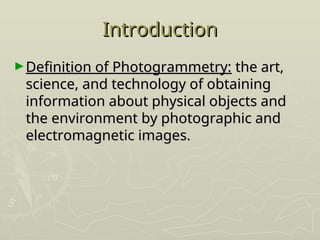
The document provides a comprehensive overview of photogrammetry, defining it as the art, science, and technology of obtaining information about physical objects and environments through images. It details its applications, variations, historical development, mathematical foundations, and processes involved in mapping and measurement. Additionally, it highlights considerations for project planning, execution, and the various challenges encountered in different terrains.

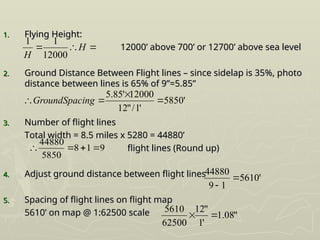
![Scale of a Vertical Photo
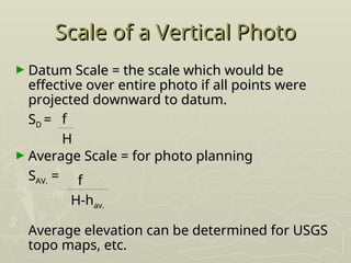
Scale of a Vertical Photo
► S = or
S = or
► f = focal length 6” or 152.4 mm is common
f = focal length 6” or 152.4 mm is common
► H’ = height of plane above ground
H’ = height of plane above ground
► h = height (elevation) of ground
h = height (elevation) of ground
► H = height of place above datum [altimeter
H = height of place above datum [altimeter
reading (2% error)]
reading (2% error)]
f
f
H
H
’
’
f
f
H-
H-
h
h](https://image.slidesharecdn.com/photogrammetry-241026120530-c95fdd2e/85/Aerial-photogrammetry-basic-concepts-and-primer-ppt-15-320.jpg)


![[Deck] What's New in Spark-Iceberg Integration via DSV2.pptx](https://cdn.slidesharecdn.com/ss_thumbnails/deckwhatsnewinspark-icebergintegrationviadsv2-260210005337-25955b12-thumbnail.jpg?width=640&height=640&fit=bounds)


