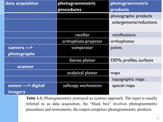
Haramaya University
CSSH
School of GeES
Department of Geo−Information Science
Aerial Photography and Photogrammetry (GISc3085)
By Kassaye Hussien (Ass. Professor)
June ,2021
1
Arial Photography and
Photogrammetry
Lessons
1. Photogrammetry
2. Principal design of aerial cameras
3. Internal camera geometry
4. Types of aerial photographs
5. Vertical aerial photographs
6. Stereo pair photographs
7. Photographic scale
8. Relief displacement
9. Image parallax
10. Air photo interpretation
11. Orthophoto
2
BY KASSAYE HUSSIEN
Objectives:
• Up on completion of the chapter you will be able to:
 Define photogrammetry,
Describe historical background of Aerial photography and
photogrammetry
Explain types of photogrammetry
Understand photogrammetric products
 Describe principal design of aerial cameras,
 Classify aerial photographs,
 Understand stereo-pair photographs,
 Define photographic scale,
 Describe relief displacement,
 Define image parallax,
 Describe airphoto interpretation techniques.
3
 What is Photogrammetry?
 Definition
 There is no universally accepted definition of
photogrammetry. The definition given below captures the
most important notion of photogrammetry.
 Photogrammetry - measuring from photographs
 The name “photogrammetry" is derived from the three Greek words
 photos – ‘light’
 gramma -that which is ‘letter or drawn or written"
 metron -to ‘measure’
•
4
1.Introduction
Cont…
 Photogrammetry is the technique of measuring objects
(2D or 3D) from photographs.
 Its most important feature is the fact, that the
objects are measured without being touched
 Photogrammetry → metric exploitation of imagery
5
Definition……
•Photogrammetry: is defined as the art, science or
technology of obtaining reliable information about physical
objects and the environment through processes of:
 recording,
 measuring, and
 interpreting photographic images
 Remember this: Photogrammetry is the metric
interpretation of image data
 Photogrammetry is a measurement technology in which
the three dimensional coordinates of points on an object
is determined.
 This is achieved by stereoscopy, which is measurements
made in two (or more) photographic images taken from
different positions (different views).
6
Cont.
•The imagery can be acquired by
 special aerial photo cameras
 video cameras
 digital cameras
 radiation sensors
• The imagery could be stored as
 conventional photographs in paper form(hardcopy)
 digital images on tape or СD(soft copy)
 The output of photogrammetry is typically a map, drawing,
measurement, or a 3D model of some real-world object
or scene.
7
• Two distinct areas are included within this definition of
Photogrammetry:
i. Metric Photogrammetry: which consists of making precise
measurements from photos and other information sources to
determine the relative locations of points.
• This enables finding distances, angles, areas, elevations,
and the sizes and shapes of objects.
ii. Interpretive Photogrammetry: deals principally in
recognizing & identifying objects and judging their
significance through careful and systematic analysis from
photographic images.
• When we can identify what we see on the photographs and
communicate this information to others, we are practicing air
photo interpretation.
8
Cont…
 These images created from satellite imagery which senses
energy in wavelengths.
 Forms basis for remote sensing (art or science of gathering
information about an object or image without actually
coming into physical contact).
 Photo interpretation involves in the study of photographic
images, while remote sensing involves not only the analysis
of photography but also the use of data collected from
remote sensing instruments.
9
Cont…
 In order to simplify understanding an abstract definition
and to get a quick grasp at the complex field of
photogrammetry, look to systems approach (Table. 1.1).
10
Cont..
data acquisition photogrammetric
procedures
photogrammetric
products
photographic products
enlargements/reductions
rectifier rectifications
orthophoto projector orthophotos
camera --->
photographs
comparator points
Stereo plotter DEMs, profiles, surfaces
scanner
analytical plotter maps
topographic maps
sensor ---> digital
imagery
softcopy workstation special maps
11
Table 1.1: Photogrammetry portrayed as systems approach. The input is usually
referred to as data acquisition, the “black box" involves photogrammetric
procedures and instruments; the output comprises photogrammetric products.
Cont…
 The first stereoplotters (Kelsh Plotter) where projection
stereoplotters
◦ they used only the light rays and optics to adjust the image
 The next was the analog stereoplotters
◦ they used more sophisticated optics to view the image.
 The analytical stereoplotter is used today.
◦ It incorporates a computer which does the work of
mathematically aligning the images so that they line up
properly.
◦ allows for storing the data and redrawing at any desired
scale.
12
Cont…
 A rectifier is kind of a copy machine for making plane
rectifications.
 Orthophoto projector generates orthophotos
 A comparator is a precise measuring instrument which lets
you measure points on a diapositive (photo coordinates).
◦ It is mainly used in aerial triangulation.
◦ In order to measure 3-D positions of points in a stereo model, a
stereo plotting instrument or stereo plotter for short, is used.
 An analytical plotter establishes the transformation
computationally. Both types of plotters are mainly used to
produce maps, DEMs and profiles.
13
14
plotter
CONT..
15
A. Analytical Stereoplotter
B. Kelsh Projection Stereoplotter
Data Acquisition…
 How can we get Data in RS? OR
 Describe the process of data acquisition in RS.
 How can we get data in Photogrammetry? Or
 Describe the process of data acquisition in PGM.
16
Data acquisition
 Data acquisition in photogrammetry is concerned with
obtaining reliable information about the properties of surfaces and
objects without physical contact with the objects which is, in
essence, the most obvious difference to surveying.
 The remotely received information can be grouped into four
categories:
 Geometric information involves the spatial position and the
shape of objects. It is the most important information source in
photogrammetry.
 Physical information refers to properties of electromagnetic
radiation, e.g., radiant energy, wavelength, and polarization.
 Semantic information is related to the meaning of an image. It
is usually obtained by interpreting the recorded data.
17
Cont…
 Temporal information is related to the change of an object in
time, usually obtained by comparing several images which were
recorded at different times.
 As indicated in Table 1.2 the remotely sensed objects may range
from planets to portions of the earth’s surface, to industrial parts,
historical buildings or human bodies.

 The generic name for data acquisition devices is sensor,
consisting of an optical and detector system. The sensor is
mounted on a platform.
 The most typical sensors are cameras where photographic
material serves as detectors. They are mounted on airplanes as
the most common platforms.
 Table 1.2 summarizes the different objects and platforms and
associates them to different applications of photogrammetry.
18
Cont…
object sensor platform specialization
planet space vehicle Space Photogrammetry (d >30km)
earth’s surface airplane space vehicle Aerial Photogrammetry (2km -10km)
industrial part tripod Industrial Photogrammetry
historical building tripod Architectural photogrammetry
human body tripod Biostereometrics
19
Table 1.2
Close Range (d <10m) andTerrestrial PGM (10m -100m)
On the basis of platforms or camera location
Check Points
 What is photogrammetry (PGM)?
 Compare and contrast RS and PGM?
 Explain the differences between metric and interpretative
photogrammetry.
 Describe the types of PGM On the basis of orientation of
camera axis, sensor system used, principle of recreating
geometry, procedure involved for reducing the data from
photographs and Applications Point of View (Reading
Assignment).
 Discuss the importance of photogrammetry in geographic
information systems.
 List field of studies that intensively apply PGM.
20
Fundamental principle of Photogrammetry
 The fundamental principle used by photogrammetry is
triangulation.
 Triangulation is the principle used by both photogrammetry
and theodolites to produce 3-dimensional point
measurements.
 By taking photographs from at least two different locations,
so-called “lines of sight” can be developed from each camera
to points on the object.
 These lines of sight (sometimes called rays owing to their
optical nature) are mathematically intersected to produce
the 3-dimensional coordinates of the points of interest.
21
CONT…
 Aerial Triangulation (AT) in Photogrammetry is
methods of determine and calculate 3D object coordinates
by photogrammetric means, by using photographs exposed
from different positions, covering the same object.
◦ measure several unknown point clearly visible in
the aerial triangulation in a stereo instrument.
◦ the inputs for aerial triangulation
 Scanned Images
 Camera Report
 Ground Control Data/ Ground Control Point
22
Cont…
 AerialTriangulation is classified three categories:
◦ Analogue Aerial Triangulation
◦ Semi Analytical Aerial Triangulation
◦ Analytical Aerial Triangulation
◦ Digital Aerial Triangulation (automation)
23
Cont…
 Advantages AT
 Minimizing delays and hardships due to adverse weather
condition.
 Access to much of the property within the project area is
not required.
 Field surveying in difficult area, such as Marshes, Extreme
slope, volcanic areas, hazardous rock formation, etc; can be
minimized.
24
Cont…
 Triangulation is also the principle used by theodolites for 3D
coordinate measurement.
 If you are familiar with these instruments, you will find many
similarities (and some differences) between photogrammetry and
theodolites.
 Triangulation is also the way your two eyes work together to
gauge distance (called depth perception).
 Two eyes can measure relative distance to scene point,
using geometric triangulation
25
Check Points
 Explain triangulation.
 Describe advantages of AT.
 What are the inputs for AT
26
Assignment one (20%)
1.What is photogrammetry? (PGM) (1%)
2. Compare and contrast RS and PGM. (2%)
3. Explain the differences between metric and interpretative.
photogrammetry. (3%)
4. Describe the types of PGM On the basis of orientation of
camera axis, sensor system used, principle of recreating
geometry, procedure involved for reducing the data from
photographs and Applications Point ofView (5%).
5. Discuss the importance of photogrammetry in geographic
information systems. (5%)
6. List field of studies that intensively apply PGM. (1%)
7. Explain triangulation. (1%)
8. Describe advantages of AT. (1%)
9. What are the inputs for AT. (1%)
27
Photogrammetry versus Remote Sensing
 The principle difference between photogrammetry and remote
sensing is in the application;
 While photogrammetrists produce maps and precise three-
dimensional positions of points, remote sensing specialists
analyze and interpret images for deriving information about
the earth’s land and water areas.
 Photogrammetry is the science of measuring distances, angles,
areas, etc. in photographs. These measurements are then able to
be mathematically transferred into “real world” measurements.
 Given that these photogrammetrically derived real-world
measurements are gathered “remotely”, i.e. not “on the ground”
or “in the real world”, enables us to label it as “remote
sensing”.
 “Remote Sensing” on the other hand, can deal with all other
sensors (e.g. RADAR, SONAR, imaging, etc. and doesn’t
necessarily rely on spatial measurements as it’s main concern.
28
Cont…
 As depicted in Fig. 1.1 both disciplines are also related to
Geographic Information Systems (GIS)
◦ they provide GIS with essential information.
◦ Quite often, the core of topographic information is produced by
photogrammetrists in form of a digital map
29
Figure 1.1: Relationship of
photogrammetry, remote sensing and GIS.
1.2 Historical Background
 Origin of photogrammetry
 aerial photography was the base for the emergence of
Photogrammetry.
 The First photographs taken in 1839
 Balloons, Kites, Pigeons were used to capture Photo
from air( till aeroplane were invented)
30
The English meteorologist E. D.
Archibald was among the first to
take successful photographs from
kites in 1882
He used a string of kites, with the
camera being attached to the last
1882
1858
Historical Background
Historical development of Aerial photograph
31
The first aerial photography taken
from an airplane was in 1909, by
Wilbur Wright.
1909
The first successful aerial
photograph from a rocket mounted
camera was taken by the Swedish
inventor, Alfred Nobel in 1897
1903
In 1903 the Bavarian Pigeon Corps used
pigeons to transmit messages and take
aerial photos. Julius Neubronne patented
the "breast mounted pigeon camera". The
camera weighed 70 grams and took
automatic exposures every 30 seconds.
1897
Cont.…
 The first photo ever taken from space on October 24, 1946
from a cool 65 miles up (104.607km), it was taken with a
35mm camera mounted on a V-2 missile launched from the
White Sands Missile Range in New Mexico.
32
Historical Background…
Satellites, Since 1972 (high resolution)
33
Check Points
 Explain the historical development of PGM
34
Photogrammetry
Photograph vs. Image
35
Historical development of Photogrammetry
 The development of photogrammetry clearly
depends on the general development of science
and technology.
 It is interesting to note that the four major phases
of photogrammetry are directly related to the
technological inventions of
 photography,
 airplanes,
 computers and electronics.
36
Check Points
 Explain the difference between photograph and Image
 Explain the historical advancement of PGM.
 Describe the relationships among PGM, RS and GIS?
37
1.3 Phases of Photogrammetry
A. First generation - Plane table photogrammetry
B. The second generation (analog photogrammetry)
C. Third Generation(Analytical)
D. The fourth generation( digital photogrammetry)
38
Phases of Photogrammetry:
 Phases of Photogrammetry:
A. First generation - Plane table photogrammetry
 Measurements made on a map on a table.
 Photographs used to extract angles.
 Photogrammetry had its beginning with the invention of
photography by Daguerre and Niepce in 1839
 First use of terrestrial photographs for topographic maps -
Laussedat, 1849 ‘Father of photogrammetry". City map of
Paris (1851).
 Film - Eastman, 1884.
39
Phases of Photogrammetry
 Major photogrammetric phases as a result of technological
innovations.
40
Phases of Photogrammetry….
B. The second generation (analoge photogrammetry) is
characterized by the invention of stereo photogrammetry by
Pulfrich (1901).
 This paved the way for the construction of the first
stereoplotter by Orel, in 1908.
 World War One was a major impetus(a driving force) to
development of aerial photography
 Airplanes and cameras became operational during the first
world war.
 Between the two world wars, the main foundations of aerial
survey techniques were built and they stand until today.
41
Analogue Photogrammetry
 Optical or mechanical instruments were used to
reconstruct three-dimensional geometry from two
overlapping photographs.
 The main product during this phase was topographic
maps
42
Optical Mechanical
Photogrammetry
 Aeroplane (Wright 1903). First aerial imagery from
aeroplane in 1909.
 The Wright brothers, Orville (August 19, 1871 –
January 30, 1948) and Wilbur (April 16, 1867 – May
30, 1912), were two American brothers, inventors.
43
Phases of Photogrammetry…..
C.Third Generation:
 With the advent of the computer, the third generation has
begun, under the motto of analytical photogrammetry
 Schmid was one of the first photogrammetrists who had
access to a computer.
 He developed the basis of analytical photogrammetry in the
fifties, using matrix algebra.
 For the first time a serious attempt was made to employ
adjustment theory to photogrammetric measurements
 Apart from aerial triangulation, the analytical plotter
(Helava 1957) is another major invention of the third
generation
 Analytical plotter - image-map coordinate transformation
by electronic computation
44
Phase of photogrammetry…..
Analytical Photogrammetry :
 The computer replaces some expensive optical and
mechanical components.
 The resulting devices were analog/digital hybrids.
 Analytical aerotriangulation, analytical plotters, and
orthophoto projectors were the main developments
during this phase.
 Outputs of analytical photogrammetry can be
topographic maps, but can also be digital products,
such as digital maps and DEMs
45
Phases of Photogrammetry…..
D.The fourth generation( digital photogrammetry)
is rapidly emerging as a new discipline in photogrammetry.
 In contrast to all other phases, digital images are used
instead of aerial photographs.
 With the availability of storage devices which permit rapid
access to digital imagery, and special microprocessor
chips, digital photogrammetry began in earnest only a few
years ago.
 The field is still in its infancy and has not yet made its way
into the photogrammetric practice.
46
Phases of Photogrammetry…..
 Digital photogrammetry:
 is applied to digital images that are stored and
processed on a computer.
 Digital photogrammetry is sometimes called softcopy
photogrammetry.
 The output products are in digital form, such as
digital maps, DEMs, and digital orthophotos saved on
computer storage media.
47
cont
 Single or pairs of digital images are loaded into a
computer with image processing capabilities.
 Images may be from satellite or airborne scanners,
CCD cameras or are conventional photographs
captured by a line scanner.
 Images are either displayed on the screen for operator
interpretation, enhanced by image processing or
subjected to image correlation in order to form a
digital elevation model (DEM) or extract details.
48
cont
 The inventions of the following devices have been
contributing the development of Digital
photogrammetry:
 Charge-Coupled Device (CCD) (Boyle, Smith 1969).
 Landsat (1972)
 Digital camera (Sesson (Eastman Kodak) 1975 - 0.01
Mpixels).
 Flash memory (Masuoka (Toshiba) 1980).
49
Why photogrammetry
 Extracting geometrical information and producing
maps.
 Cheaper than terrestrial methods.
 Extracting qualitative information.
 High speed of map generation.
50
Why photogrammetry……..
 Ideal technology when measuring objects such as
– Vast regions to be mapped
– Irregular shapes and
– Objects that are too
• Hot or cold
• Soft
• Delicate(very fine in texture)
• Inaccessible
• Toxic
• Radioactive to touch
51
Photogrammetric products
A.Planimetric maps –
Planimetric elements in geography are those features that
are independent of elevation, such as roads, building
footprints, and rivers and lakes. They are represented on
two-dimensional maps as they are seen from the air, or in
aerial photography. These features are often digitized from
orthorectified aerial photography into data layers that can
be used in analysis and cartographic outputs.
B.Topographic maps –
A type of map characterized by large-scale detail and
quantitative representation of relief, using contour lines.
Traditional definitions require a topographic map to show
both natural and man-made features. A topographic map is
typically published as a map series.
52
Photogrammetric products…..
 Photomap (Orthophotos)
 DEM/ DTM
 Virtual landscapes
 Nadir imagery is essential for mapping
 Overlap and side lap is required to give 3D information
 Note that
 Maps are the most prominent product of
photogrammetry.
 They are produced at various scales and degrees of
accuracies.
 Planimetric maps contain only the horizontal
position of ground features while topographic maps
include elevation data, usually in the form of contour
lines and spot elevations.
 Thematic maps emphasize one particular feature, e.g.,
transportation network.
53
1.4 Applications of photogrammetry
Topographical mapping:
• The plotting of map detail and contours is normally
carried out using aerial photogrammetric methods
• These methods are used for both original survey and
revision, and replace classical ground methods except
where the task is so small that flying is uneconomical
• The technique needs a certain amount of ground
surveyed control, but this requirement is being
continually reduced with the improvement of aerial
triangulation techniques to provide supplementary
control.
• A final Field check is necessary
54
Applications of photogrammetry
 Large Scale Plans:
• Large scale plans can be produced accurately and
quickly by air survey methods, but requires thorough
checking.
• by archaeologists to quickly produce plans of large
or complex sites
• by meteorologists as a way to determine the actual
wind speed of a tornado where objective weather
data cannot be obtained
• For large tasks such as road building and major
constructions, air survey methods are quicker and
cheaper than ground methods.
• profiles for determination of earthwork quantities can
be simply obtained using aerial photographs.
55
Applications of photogrammetry
• Land use maps
• Hydrographical maps: mapping coast lines etc.,
• Exploration and reconnaissance
• Terrestrial and Scientific uses
– Detailed surveying of historic buildings
– Traffic accidents
– Medical applications etc.,
• Stereoscopic applications and measurements
56
Applications of photogrammetry
• Cadastral Maps:
• Similar types and advantages compare to large scale
maps can be gained here.
• Ground techniques are accurate but not required in
all cases.
•Airphoto techniques provides necessary information
with adequate accuracy.
57
Check Points
 Discuss the photogrammetric applications in GIS. 5%
 Explain why photogrammetry is important field of study. 2%
 Explain the difference between photograph and Image.1%
 Explain the historical advancement of PGM. 4%
 Discus in brief, the phases of photogrammetry.5%
58
1.5 Basic Categories
► Photogrammetric Types from Applications Point
of View (d is distance from camera to object)
A. Close range d<10 m
B. Terrestrial Photogrammetry10 m<d<100 m
 Photographs are taken from fixed position on or
near the ground with camera distance settings to
finite values
C. Aerial Photogrammetry (Far range)2km<d<10
km
 Photographs are taken by a camera mounted in an
aircraft flying over the area with camera distance
setting to indefinite
D. Space Photogrammetry (Furthest Range) 30
km<d
59
Types of Photogrammetry…..
 Aerial and Space Photogrammetry
 Used for mapping Earth or planets
 Imaging system is based on an aircraft or spacecraft
 Target is the ground surface
 Image data is processed to create new spatial
information products
 Close range photogrammetry
 Used for industrial measurement
 Imaging system is handheld
 Target is the object being measured
 Image data is processed to make precise
measurements
60
Close Range Photogrammetry
61
Terrestrial Photogrammetry
Terrestrial:
62
Aerial Photogrammetry
Aerial Photo:
63
Space Photogrammetry
Space Photogrammetry:
64
Space Photogrammetry
Space Photogrammetry:
65
Activities
1.How archaeologists and meteorologists apply photogrammetry?
2.List and describe Photogrammetric Types from Applications Point of
view?
3.Discuss the relationship among RS,GIS, aerial photography and
photogrammetry.
4.Explain the evolution or historical development of Photogrammetry.
5.What are the most important products of photogrammetry?
6.Define photogrammetry.
7.Assume you are an expert of producing topographic map of Ethiopia. How
can you produce this extensive map?
66
Lesson 2. Camera
 most fundamental device in the field of photogrammetry
 It is the basic instrument which acquires images, from which
photogrammetric products are produced.
 Single-lens frame cameras are the most common cameras in
use today
 Imaging devices can be categorized according to how the
image is formed:
1.Frame cameras
2.strip cameras, linear array sensors, or pushbroom scanners
3.flying spot scanners or whiskbroom scanners
67
68
Scan line
Cont…
69
70
2.1. Principle design of aerial cameras
• Cameras are framing systems which acquire a snapshot of
an area (A), of the surface.
• Camera systems use a lens (B) (or system
of lenses collectively referred to as the optics)
to form an image at the focal plane (C), the
plane at which a film is placed and image
is registered.
• Cameras can be used on a variety
of platforms including ground-
based stages, helicopters, aircraft,
and spacecraft.
71
72
73
74
 Camera Body = houses camera driving mechanism, driving
monitor, operating handles and electrical connections, switches and
other accessories
 Film magazine – container of films
 Focal plane = all light ray through lens cone come to focus
 The focal length of the lens is the distance between the lens and
the image sensor.
 Diaphragm and Shutter regulate the amount of light which will
expose the photograph.
 Shutter controls the length of time that light is permitted to pass
through the lens.
 The lens cone assembly Contains the lens, shutter, and
diaphragm
 The filter serves three purposes:
 (1) It reduces the effect of atmospheric haze,
 (2) it helps provide uniform light distribution over the entire
format, and
 (3) it protects the lens from damage and dust.
2.2. Internal camera geometry
• Lens: the most important and expensive component and is
used for projecting an optical image onto the film.
• Focal length (principal distance) together
with the flying height, it determines the photo
scale.
• The focal length also determines the angle
of view of the camera and determines the area "seen" by the
camera.
• Position of principal point is defined by fiducial marks,
mounted on the frame of the camera.
• Fiducial marks are also
required to align(arrange) photos
for stereoviewing.
75
Internal camera geometry
76
Photo Scale
 Map scale
 S (Scale) = MD (Map Distance)/GD (Ground Distance)
 Photo Scale
 S = PD (Photo Distance)/GD
77
(When Computation of scale from terrain level).
(When the ground elevation is at sea level, h becomes zero)
2.3.Types of Camera
Types of Camera:
 Aerial cameras can be classified in a number of ways:
1. By lens type: single lens, multiple lens.
2. By angular field: normal angle-up to 75ᵒ; wide angle-
75ᵒ to 100ᵒ;and, super wide angle-100ᵒ and above.
3. By focal length: short-up to 6 inches; normal-6 to 12
inches; and, long-more than 12 inches.
4. By use: reconnaissance, mapping and special
78
Check Points and Assignment 2 (25%)
1.Name and briefly describe the main parts of a frame aerial
mapping camera.4%
2. List and briefly describe the three geometric categories of
imaging devices.4%
3. Explain why photogrammetry is important field of study.
2%
4. Explain the difference between photograph and Image.1%
5. Explain the historical advancement of PGM. 4%
6. Discus in brief, the phases of photogrammetry.3%
7. Discuss the difference among ground based, aerial and
Space photographs.3%
8. Explain the advantages of aerial photographs.2%
9. Discuss the difference between swath and nadir.2%
79
Lesson 3.Aerial Photography
 The term "photography" is derived from two Greek
words meaning "light"(photo) and "writing" (graphien).
 Photography is production of permanent images by means of
the action of light on sensitized surfaces (film or array inside
a camera), which finally giving rise to a new form of visual
art.
 Aerial Photography means photography from the air
 Aerial photography is the taking of photographs of the
ground from an elevated/direct-down position.
 Usually the camera is not supported by a ground-based
structure 80
 Platforms for aerial photography include:
 fixed-wing aircraft,
 helicopters,
 multirotor Unmanned Aircraft Systems (UAS),
 balloons,
 blimps and dirigibles (airships),
 rockets, pigeons, kites, parachutes, stand-alone
telescoping and vehicle-mounted poles.
 Mounted cameras may be triggered (cause to function)
remotely or automatically; hand-held photographs may be
taken by a photographer.
81
82
Aerial photography ……
Note Aerial photography should not be confused with air-to-
air photography, where one or more aircraft are used as chase
planes that "chase" and photograph other aircraft in flight.
83
Historical Background of Aerial photography
Read Historical Background of photogrammetry.
Assignment two
1.Discuss the history of Aerial photography.
2.Discuss the difference among ground based, aerial and
Space photographs.
3.Explain the advantages of aerial photographs.
4.List the components of aerial camera.
5.Discuss the difference between swath and nadir.
84
3.2 Advantages of Aerial Photography
 Advantages of Aerial Photography over Ground-Based
Observation:
 Aerial photography offers an improved vantage point.
 Aerial photography has the capability to stop action.
 It provides a permanent recording.
 It has broader spectral sensitivity than the human eye.
 It has better spatial resolution and geometric fidelity
(reliability) than many ground-based sensing methods.
85
3.3 Applications of Aerial Photography…..
 Applications of Aerial Photography:
 Land-Use Planning and Mapping
 Geologic Mapping
 Archaeology
 Species Habitat Mapping
 Integration of Aerial Photography into GIS
 Digital Image Processing
86
3.4 Characteristics of Aerial Photography…
1. Synoptic Viewpoint:
 Aerial photographs give a bird's eye view of large areas
enabling us to see surface features in their spatial context
(general view of a whole).
 They enable the detection of small scale features and
spatial relationships that would not be found on ground.
87
Characteristics of Aerial Photography…
2.Time freezing ability:
 They are virtually permanent records of the existing
conditions on the Earth’s surface at one point in time, and
used as an historical document.
3. Capability to stop action:
 They provides a stop action view of dynamic conditions
and are useful in studying dynamic phenomena such as
flooding, moving wildlife traffic, oil spills, forest fires
88
Characteristics of Aerial Photography…
4.Three dimensional perspective:
 It provides a stereoscopic view of the Earth’s surface and
make it possible to take measurements horizontally and
vertically
 a characteristic that is lacking for the majority of remotely
sensed data.
5. Spectral and spatial resolution:
 Aerial photographs are sensitive to radiation in
wavelengths that are outside of the spectral sensitivity of
the human eye (0.3 μm to 0.9μm versus 0.4 μm to 0.7 μm).
89
Characteristics of Aerial Photography…
6.They are sensitive to objects outside the spatial resolving
power of human eye.
7. Availability:
 Aerial photographs are readily available at a range of
scales for much of the world.
8. Economy:
 They are much cheaper than field surveys and are often
cheaper and more accurate than maps.
90
3.5 Types of aerial photographs
• Two types:
 Vertical aerial photographs( Axis of camera vertical < 3˚)
 Oblique aerial photographs(Axis of camera inclined to vertical line
> 3˚)
• Photographs that are tilted less than 3° off the vertical
are regarded as vertical.
•
91
Cont…
92
Camera axis < 3° inclined by 30° tilted by 60°
93
Cont…
•Vertical aerial photographs:
 Lens axis is perpendicular to the surface.
 It covers a relatively small area.
 The ground area covered by a single photograph
approximates the shape of a square or rectangle.
 Relief is not readily apparent.
 Distances and directions vary across the photograph
unless the ground is flat.
 It provides a bird’s-eye view of the area which is not the
normal view experienced by people in the area.
94
Types of aerial ...
• Oblique photographs are taken with the angle from the
vertical deliberately set somewhere between 3° and 90°.
•
95
Cont…
•They are termed
 low oblique if the horizon is not visible on the photograph
 high oblique if the horizon is visible.
• Low oblique photographs:
 The camera lens system is inclined by usually 30°.
 Covers a relatively small area.
 The ground area covered is trapezoidal
although the photograph is square.
Since scale varies over the photograph,
distances and directions are not true.
 Relief can be seen but it is distorted.
 The horizon is not visible.
 The objects have a more familiar view which resembles the view
the observer would get from a high vantage(places affording good
view) point such as a hill or the roof of a high building.
96
Types of aerial ...
• High oblique photographs:
 The camera is tilted about 60° from the vertical.
 The horizon is always visible.
 It covers a very large area.
 The ground view is trapezoidal
though the photograph is square.
 Familiarity of the view varies
depending on the height from which
the photograph was taken.
 Scale is variable therefore distance and directions on the
photograph are not true.
 Relief can be seen but it is sometimes distorted.
97
Types of aerial photographs:
In general we have two major Types of photographs
(categorized by tilt)
98
Types of aerial photographs:
99
Fig. Geometry of vertical, oblique and horizontal
photographs.
100
VERTICAL LOW OBLIQUE HIGH OSLIQUE HORIZONTAL
• Advantages of vertical photographs over oblique
 Vertical photographs give approximate uniform scale over
the photograph but oblique photos do not.
 Measuring distances and directions on vertical photos are
therefore easier and more accurate.
 In flat areas the vertical photos can almost be used as a
map.
 Since scale of the vertical photos is nearly constant, scale
and directions can be measured in the same
way as those on a map.
 Limited geometric distortions.
 Stereoscopic study on vertical photos
is more effective than on oblique photos.
Constant scale makes interpretation easier and tall buildings
do not hide data as they do on oblique photos.
101
• Advantages of oblique photographs over vertical
 Oblique photos give a more natural view of ground features
especially buildings, bridges etc.
 Oblique photos cover more ground area than vertical
photos from the same altitude and focal length.
 Oblique photos can give cover in areas where low cloud
might obscure(hidden) the ground using vertical photos.
 Determination of feature elevations is more accurate on
oblique photos than on vertical photos.
 Cameras can be cheaper since
photography not used for precision
photogrammetry.
 Tree canopy or other tall buildings
can mask detail on vertical photos which may be visible on
oblique photos.
102
3.6 Taking vertical aerial photographs
• When taking vertical aerial photographs, the aircraft
flies in a series of lines, each called a
flight run (A).
• Photos are taken in rapid succession
looking straight down at the ground,
often with a 60% overlap between next photos.
• The overlap ensures total coverage along a flight line
and also facilitates stereoscopic viewing.
•.
103
Lateral or Side overlap(Side Lap) and Forward Overlap (End Lap))
104
Lateral Overlap (Side Lap) Forward Overlap (End Lap)
Air Base and End lap….
105
TakingVertical Aerial Photograph
Tips!!
106
Basic geometry of a vertical aerial
photograph.
107
Illustration of imaging for a nadir-viewing camera
108
Focal Length, Coverage and Quality
 Focal length and quality of photo has direct relation
 Focal length and coverage has invers relation.
 Coverage = F(f,Al and Format of camera)
109
3.7 Stereo pair of photographs
• Successive photo pairs display the overlap region from
different perspectives and
• can be viewed through a device called a stereoscope to
see a three-dimensional view of the area, called a stereo
model.
• Two next images form a stereopair
(A)+(B) which allows to perceive a
stereo model within overlapping area
(C).
• Single image allows to measure planimetric (X,Y)
coordinates of an object.
• Stereopair allows to retrieve 3D coordinates (X,Y,Z) of
the object.
110
Overlap Between Runs
30% overlap between
runs or swaths
111
Run #1
Run #2
Presentation Assignment
1. Describe the difference between nadir and swath 1%
112
2.What is the primary difference between high and low
oblique aerial photographs? 1%
3. Define the following photogrammetric terms: end lap,
side lap, stereopair, exposure station, and flying height. 1%
4. Discuss the importance of photogrammetry in geographic
information systems. 3%
5. Presentation 4%
3.8 Photographic scale
• The amount of detail shown in an aerial photograph is
dependent, among other things, on the scale of
photograph.
• “photograph scale” is an expression that states one
unit / any unit/ of distance on a photograph represents a
specific number of units of actual ground distance.
• Scales may be expressed as unit equivalents,
representative fractions, or ratios.
1mm = 25m ( unit equivalent), or
1/25,000 (Representative Fraction), or
1:25,000 (Ratio).
• The scale of a vertical photograph approximately
equals to the ratio of the flying height above the ground
(H) and the focal length of the camera lens (f).
113
• For a vertical photograph taken over flat terrain, scale
is a function of the focal length (f) of the
camera used to acquire the image and
the flying height above the ground (H)
from which the image was taken.
114
H
f
S 
ave
ave
h
H
f
S


• If the photographed terrain varies in
elevation, object distance will also vary
and photo scale will like wise vary.
• Photo scale increases with increasing
terrain elevation and decreases with
decreasing terrain elevation.
3.10. Image Displacement
 The difference between an accurate planimeteric
map and a vertical aerial photograph lies in the
fact that the former depicts all features at their
correct horizontal position whereas the images on
the latter are generally displaced from their true
plane position because of (causes of image
displacement):
 (i)Photographic deficiencies ;
 (ii) Ground relief ;
 (iii) and Tilt of the camera.
115
cont
3.11. Displacement due to Photographic Deficiencies
 Displacement due to photographic deficiencies can be
caused by:
 inferior lens,
 faulty assemblage of camera,
 faulty shutter,
 film shrinkage and
 the failure of the film-flattening mechanism at the
camera focal plane.
 These deficiencies may result in a noticeable lack of
sharpness in the images
116
3.12. Relief Displacement
•.
117
• The figure shows displacement due to relief in a single
photograph. (A) as the photograph is taken, (B) as the
photograph appears.
 Variations in ground relief is the most significant source of image
displacement on vertical aerial photographs.
 The image of any feature lying above or below the horizontal ground
surface (datum plane) would be displaced on a vertical aerial photograph
from its true plan position.
cont
 Relief displacement is the shift or displacement in the
photographic position of an image caused by the relief
of the object, i.e., its elevation above or below a
selected datum.
 This displacement is outward for objects above the
datum and inward for objects below the datum
d = relief displacement (mm)
r = radial distance from nadir (mm)
h = height of the terrain above reference plane (m)
H = flight altitude above reference plane (m)
118
cont
• The direction of displacement is Radial from the Nadir(N)
of the photograph
• In a truly vertical photograph where nadir (N) coincides
with principal point (PP) of the photograph, the following
facts will hold good:
1.The topographic displacement varies directly with the height
of the object and the distance between the object and the
principal point (nadir).
2.Relief displacement is radial from the nadir and all objects of
the same height and equidistance from the nadir in any
direction will be displaced the same amount.
3.There is no displacement at nadir.
4.Objects projecting above a selected datum are displaced
radially outward from the optical centre of the photo principal
point (PP) on a line passing through the true plane position of'
the object.
119
cont
5.Relief displacement varies inversely with the height of
the photography. Greater will be the flying height lesser
displacement:
6.Relief displacement varies directly with the height of
the object. Taller objects are displaced more than shorter
objects.
120
• As the distance from the principal point increases, the
relief displacement increases.
• Objects not under the principal point will lean
outward.
• Towers A and B are equally high, but placed at
different distances from the nadir point, thus have
different relief displacements.
• Objects directly below center
of camera lens (i.e. at the nadir)
will have only their tops visible.
121
• Relief displacement increases
as the elevation of the point
increase.
3.13 Image Parallax
• Image Parallax is an apparent displacement of an object when seen from
two different points.
•In case of aerial photographs an object is viewed or photographed from
two different positions.
•Consequently, an apparent shift in the position of that object takes place,
which is referred to as parallaxes displacement.
•Parallax refers to the apparent change in relative positions of stationary
objects caused by a change in viewing position.
• The change in position of an image from one photograph to the next
caused by the aircraft’s motion is termed stereoscopic parallax or simply
parallax.
• Parallax of any point is directly related to the elevation of the point, and
that parallax is greater for high points than low points.
• Variation of parallax with elevation provides the fundamental basis for
determining elevations of points from photographic measurements (3D
view).
122
Cont…
Parallax
123
cont
 Types of Parallax
 Parallax is of two types:
1. Absolute parallax (X-parallax) –
 displacement along or parallel to the line of flight and
is represented by the algebraic difference of the
distances of corresponding images from their
respective nadirs when measured parallel to the line of
flight.
2. Y-parallax –
 displacement at right angles to the line of flight.
 Y-parallax is not commonly used in aerial
photography for forestry purposes
124
• The absolute stereoscopic parallax (x-parallax) P at a
point is defined to be the algebraic difference, measured
parallel to the line of flight, of the distances of the two
images from their respective principal points.
125
• Displacement in stereoscopic
pairs of photographs. A) as the
photographs are taken, B) as
the photos appear. Similar
triangles are used to derive the
basic parallax formula .
where:
h = height of object
H = flying height of the aircraft above
the base of the object
P = absolute stereoscopic parallax at
the base of the object
dP = parallax difference between the top of the object and the base of the
object.
• Aerial photographs have the following advantages over
maps:
 It provides a current pictorial view as opposed to a
symbolic representation of the survey area
 It is more readily obtained, the mapping process
which often includes aerial photography, can take
months to complete.
 It can be used to provide information of inaccessible
areas.
 It shows things that are often omitted from maps.
 It provides a permanent synoptic(wide view) record
of an area which can be used to compare with earlier
or later photographs to monitor changes in an area.
126
• The following are disadvantages of photographs
compared to maps:
Position location and scale are only approximate.
Ground features are difficult to identify or interpret
without the symbols that appear on maps
Some features are obscured(being out of sight) by
other ground detail, buildings in forests for example.
Obtaining relief information requires stereoscopic
overlapping photographs and a stereoscope.
The absence of contrasting colour or tone makes
interpretation difficult in poor lighting conditions.
There is no marginal data to assist in its
interpretation.
It requires skill and training to use effectively.
127
4. Air photo Interpretation
• Aerial photographs contain a detailed record of features
on the ground at the time of data acquisition.
• Photographic interpretation is the act of examining
photographic images for the purpose of identifying
objects and judging their significance.
• Success in photo interpretation varies with:
 training and experience of the interpreter
 nature of the objects or phenomena being interpreted
quality of the photographs being utilized
• A photo interpreter systematically examines the photos
and, frequently, other supporting materials such as maps
and reports of field observations.
128
4.1 Elements of Airphoto Interpretation
• A systematic study of aerial photographs usually
involves several basic characteristics of features shown
on a photograph.
• The exact characteristics useful for any specific task
depend on the field of application.
• Most applications consider the following basic
characteristics, or variation of them:
 Shape
 Size
 Pattern
 Tone
 Texture
 Shadow
 Site
 Association
129
i. Shape: refers to the general form, configuration, or
outline of individual objects.
• Many features possess characteristic shapes that
readily identify the features.
• In the case of stereoscopic photographs, the object’s
height also defines its shape.
• Anthropogenic features usually appear as straight or
smooth curved lines, while natural features usually
appear to be irregular.
• Some of the most prominent man-made features are
highways, railroads, bridges, canals, and buildings.
• For example, a railroad is usually readily distinguished
from a highway because its shape consists of long
straight tangents and gentle curves as opposed to the
curvy shape of a highway.
130
131
This is a baseball diamond next to a track and field area.
ii. Size: of objects on photographs must be considered in
the context of the photo scale.
• In the use of size as a diagnostic characteristic both the
relative and absolute sizes of objects can be important.
• The size of objects can be important in discrimination of
objects and features (cars vs. trucks or buses; bush vs.
trees, etc.).
• The size of unknown objects on a photograph, as
determined from the scale of the photograph or a
comparison with known objects of known size, gives a
clue to their identity.
• For example, in a built-up area the smaller buildings are
usually dwellings, and the larger buildings are
commercial or community buildings.
132
iii. Pattern: relates to the spatial arrangement of objects.
• It is the regular arrangement of objects that can be
diagnostic of features on the landscape.
• The repetition of certain general forms or relationships
is characteristic of many objects
• Both man made & natural gives objects a pattern that
aids the photo interpreter in recognizing them.
• Pattern can be either man-made or natural.
• Pattern can also be very important in geologic or
geomorphologic analysis.
• Example, drainage pattern can tell the trained observer
a great deal about the lithology and structural patterns in
an area.
133
134
Pattern is another
principle that helps us
identify trees.
The man-made
patterns of fields,
orchards, and roads
contrast with
nature's patterns of
river and forest.
iv. Tone (colour): refers to colour or relative brightness
of objects on photographs.
• Tone can be defined as each distinguishable variation
from white to black.
• It is related to reflectance of light from objects.
• With out tonal differences, the shapes, patterns, &
textures of objects could not be discerned or detected.
135
v. Texture: is the frequency of tonal change on the
photographic image.
• It is a product of their individual shape, size, pattern,
shadow, and tone.
• As the scale of the photograph is reduced, the texture
of any given object or area becomes progressively finer
and ultimately disappears.
• An interpreter can often distinguish between features
with similar reflectance based on their texture
differences.
• An example would be the smooth texture of green
grass as contrasted with the rough texture of green tree
crowns on medium scale aerial photos.
136
vi. Shadows: are important to interpreters in two
opposing respects:
 the shape or outline of a shadow affords an impression of
the profile view of objects (which aids interpretation), and
 objects within shadows reflect little light and are difficult to
discern on photographs (which hinders interpretation)
• Shadows are very helpful in identifying features since
they show the familiar side view of the object.
• Some excellent examples are the shadows of water
towers or cooling towers and bridges.
• When viewed directly from above, only a round circle
or dot is seen, whereas the shadow shows the profile
and helps to identify the object.
• Relative lengths of shadows also usually give a good
indication of relative heights of objects; however the
length of a shadow will also depend on other factors
such as the time of day and year.
137
138
139
140
141
• Bridge (Shadow): Shadow is
another principle of photo
interpretation.
• An object's shadow often
gives us as much information
as the object itself.
• On this larger scale photo, it's
easy to see the design of the
steel superstructure and the
piers by looking at the
shadows.
vii. Site: refers to topographic or geographic location
and is particularly important aid in interpretation.
• Agricultural crops may like certain conditions.
• Man made features may also be found on rivers (e.g.
power plant) or on a hill top (observatory or radar
facility).
• For example, certain tree species would be expected to
occur on well-drained upland sites, whereas other tree
species would be expected to occur on poorly drained
lowland sites.
• Various tree species occur only in certain geographic
areas (e.g., “teff” occurs in “Kolla” but not in “Dega”).
142
viii. Association: refers to the occurrence of certain
features in relation to others.
• Quite often an object not easily recognized by itself
may be identified by its relative position to surrounding
objects.
• Naturally some features are found in association with
others.
• For example, a church with its compound might be
difficult if it is located in a forest, but would be easy to
identify if it is sited in an area of low forest cover.
• Schools at different levels typically have characteristic
playing fields, parking lots, and clusters of buildings in
urban areas.
143
144
This is an air port because
of its shape and because
there are air planes.
4.2 Airphoto interpretation keys
• Two general types of airphoto interpretation keys exist:
 Selective key
 Elimination key
• A selective key: contains numerous photographic
examples with supporting text.
• The interpreter simply selects that example that most
closely corresponds to the object he/she is trying to
identify, e.g. industries, landforms, etc.
• An elimination key: takes a hierarchical structure of a
set of alternatives in which the interpreter eliminates
various criteria from the classification.
• The interpreter follows a precise step-wise process that
leads to the elimination of all items except the one
(ones) that he/she is trying to identify.
145
4.3. Airphoto Interpretation Equipment
• Stereoscope: is an instrument which facilitates the
stereo viewing process.
146
Mirror stereoscope
Lens stereoscope
• Many applications of
aerial photography use
stereoscopic coverage
and stereo viewing.
Airphoto Interpretation Equipment
Tips!
Types of air photo interpretation:
1.Lens Type Stereoscope - is the simplest optical instrument for
viewing objects in three dimensions.
2.Prism Type Stereoscope - consists of two thin prisms which are
fixed in a stand and are used for viewing stereo-pairs.
3. Mirror Type Stereoscope(reflecting stereoscope) - The
superiority of this stereoscope over the other two types of
stereoscopes lies in the fact that it affords full separation of the
stereoscopic pair of photographs.
 And provides full view of the entire stereoscopic model under
normal observing (no magnification) conditions
147
5. Orthophoto
• Orthophoto combines the image characteristics of an
aerial photograph with the geometric qualities of a map.
• Unlike normal aerial photographs, distortions and
relief displacement are removed so ground features are
displayed in their true planimetrically correct position.
• Orthophotography is the process of making an
orthophoto.
• Accurate measurements of distance, area and
directions can be made, however
should not be used for detailed
photo interpretation due to a loss
in resolution.
148
149

Aerial photogrammetry chapter pptx-1.pdf

  • 1.
    Haramaya University CSSH School ofGeES Department of Geo−Information Science Aerial Photography and Photogrammetry (GISc3085) By Kassaye Hussien (Ass. Professor) June ,2021 1
  • 2.
    Arial Photography and Photogrammetry Lessons 1.Photogrammetry 2. Principal design of aerial cameras 3. Internal camera geometry 4. Types of aerial photographs 5. Vertical aerial photographs 6. Stereo pair photographs 7. Photographic scale 8. Relief displacement 9. Image parallax 10. Air photo interpretation 11. Orthophoto 2 BY KASSAYE HUSSIEN
  • 3.
    Objectives: • Up oncompletion of the chapter you will be able to:  Define photogrammetry, Describe historical background of Aerial photography and photogrammetry Explain types of photogrammetry Understand photogrammetric products  Describe principal design of aerial cameras,  Classify aerial photographs,  Understand stereo-pair photographs,  Define photographic scale,  Describe relief displacement,  Define image parallax,  Describe airphoto interpretation techniques. 3
  • 4.
     What isPhotogrammetry?  Definition  There is no universally accepted definition of photogrammetry. The definition given below captures the most important notion of photogrammetry.  Photogrammetry - measuring from photographs  The name “photogrammetry" is derived from the three Greek words  photos – ‘light’  gramma -that which is ‘letter or drawn or written"  metron -to ‘measure’ • 4 1.Introduction
  • 5.
    Cont…  Photogrammetry isthe technique of measuring objects (2D or 3D) from photographs.  Its most important feature is the fact, that the objects are measured without being touched  Photogrammetry → metric exploitation of imagery 5
  • 6.
    Definition…… •Photogrammetry: is definedas the art, science or technology of obtaining reliable information about physical objects and the environment through processes of:  recording,  measuring, and  interpreting photographic images  Remember this: Photogrammetry is the metric interpretation of image data  Photogrammetry is a measurement technology in which the three dimensional coordinates of points on an object is determined.  This is achieved by stereoscopy, which is measurements made in two (or more) photographic images taken from different positions (different views). 6
  • 7.
    Cont. •The imagery canbe acquired by  special aerial photo cameras  video cameras  digital cameras  radiation sensors • The imagery could be stored as  conventional photographs in paper form(hardcopy)  digital images on tape or СD(soft copy)  The output of photogrammetry is typically a map, drawing, measurement, or a 3D model of some real-world object or scene. 7
  • 8.
    • Two distinctareas are included within this definition of Photogrammetry: i. Metric Photogrammetry: which consists of making precise measurements from photos and other information sources to determine the relative locations of points. • This enables finding distances, angles, areas, elevations, and the sizes and shapes of objects. ii. Interpretive Photogrammetry: deals principally in recognizing & identifying objects and judging their significance through careful and systematic analysis from photographic images. • When we can identify what we see on the photographs and communicate this information to others, we are practicing air photo interpretation. 8
  • 9.
    Cont…  These imagescreated from satellite imagery which senses energy in wavelengths.  Forms basis for remote sensing (art or science of gathering information about an object or image without actually coming into physical contact).  Photo interpretation involves in the study of photographic images, while remote sensing involves not only the analysis of photography but also the use of data collected from remote sensing instruments. 9
  • 10.
    Cont…  In orderto simplify understanding an abstract definition and to get a quick grasp at the complex field of photogrammetry, look to systems approach (Table. 1.1). 10
  • 11.
    Cont.. data acquisition photogrammetric procedures photogrammetric products photographicproducts enlargements/reductions rectifier rectifications orthophoto projector orthophotos camera ---> photographs comparator points Stereo plotter DEMs, profiles, surfaces scanner analytical plotter maps topographic maps sensor ---> digital imagery softcopy workstation special maps 11 Table 1.1: Photogrammetry portrayed as systems approach. The input is usually referred to as data acquisition, the “black box" involves photogrammetric procedures and instruments; the output comprises photogrammetric products.
  • 12.
    Cont…  The firststereoplotters (Kelsh Plotter) where projection stereoplotters ◦ they used only the light rays and optics to adjust the image  The next was the analog stereoplotters ◦ they used more sophisticated optics to view the image.  The analytical stereoplotter is used today. ◦ It incorporates a computer which does the work of mathematically aligning the images so that they line up properly. ◦ allows for storing the data and redrawing at any desired scale. 12
  • 13.
    Cont…  A rectifieris kind of a copy machine for making plane rectifications.  Orthophoto projector generates orthophotos  A comparator is a precise measuring instrument which lets you measure points on a diapositive (photo coordinates). ◦ It is mainly used in aerial triangulation. ◦ In order to measure 3-D positions of points in a stereo model, a stereo plotting instrument or stereo plotter for short, is used.  An analytical plotter establishes the transformation computationally. Both types of plotters are mainly used to produce maps, DEMs and profiles. 13
  • 14.
  • 15.
    CONT.. 15 A. Analytical Stereoplotter B.Kelsh Projection Stereoplotter
  • 16.
    Data Acquisition…  Howcan we get Data in RS? OR  Describe the process of data acquisition in RS.  How can we get data in Photogrammetry? Or  Describe the process of data acquisition in PGM. 16
  • 17.
    Data acquisition  Dataacquisition in photogrammetry is concerned with obtaining reliable information about the properties of surfaces and objects without physical contact with the objects which is, in essence, the most obvious difference to surveying.  The remotely received information can be grouped into four categories:  Geometric information involves the spatial position and the shape of objects. It is the most important information source in photogrammetry.  Physical information refers to properties of electromagnetic radiation, e.g., radiant energy, wavelength, and polarization.  Semantic information is related to the meaning of an image. It is usually obtained by interpreting the recorded data. 17
  • 18.
    Cont…  Temporal informationis related to the change of an object in time, usually obtained by comparing several images which were recorded at different times.  As indicated in Table 1.2 the remotely sensed objects may range from planets to portions of the earth’s surface, to industrial parts, historical buildings or human bodies.   The generic name for data acquisition devices is sensor, consisting of an optical and detector system. The sensor is mounted on a platform.  The most typical sensors are cameras where photographic material serves as detectors. They are mounted on airplanes as the most common platforms.  Table 1.2 summarizes the different objects and platforms and associates them to different applications of photogrammetry. 18
  • 19.
    Cont… object sensor platformspecialization planet space vehicle Space Photogrammetry (d >30km) earth’s surface airplane space vehicle Aerial Photogrammetry (2km -10km) industrial part tripod Industrial Photogrammetry historical building tripod Architectural photogrammetry human body tripod Biostereometrics 19 Table 1.2 Close Range (d <10m) andTerrestrial PGM (10m -100m) On the basis of platforms or camera location
  • 20.
    Check Points  Whatis photogrammetry (PGM)?  Compare and contrast RS and PGM?  Explain the differences between metric and interpretative photogrammetry.  Describe the types of PGM On the basis of orientation of camera axis, sensor system used, principle of recreating geometry, procedure involved for reducing the data from photographs and Applications Point of View (Reading Assignment).  Discuss the importance of photogrammetry in geographic information systems.  List field of studies that intensively apply PGM. 20
  • 21.
    Fundamental principle ofPhotogrammetry  The fundamental principle used by photogrammetry is triangulation.  Triangulation is the principle used by both photogrammetry and theodolites to produce 3-dimensional point measurements.  By taking photographs from at least two different locations, so-called “lines of sight” can be developed from each camera to points on the object.  These lines of sight (sometimes called rays owing to their optical nature) are mathematically intersected to produce the 3-dimensional coordinates of the points of interest. 21
  • 22.
    CONT…  Aerial Triangulation(AT) in Photogrammetry is methods of determine and calculate 3D object coordinates by photogrammetric means, by using photographs exposed from different positions, covering the same object. ◦ measure several unknown point clearly visible in the aerial triangulation in a stereo instrument. ◦ the inputs for aerial triangulation  Scanned Images  Camera Report  Ground Control Data/ Ground Control Point 22
  • 23.
    Cont…  AerialTriangulation isclassified three categories: ◦ Analogue Aerial Triangulation ◦ Semi Analytical Aerial Triangulation ◦ Analytical Aerial Triangulation ◦ Digital Aerial Triangulation (automation) 23
  • 24.
    Cont…  Advantages AT Minimizing delays and hardships due to adverse weather condition.  Access to much of the property within the project area is not required.  Field surveying in difficult area, such as Marshes, Extreme slope, volcanic areas, hazardous rock formation, etc; can be minimized. 24
  • 25.
    Cont…  Triangulation isalso the principle used by theodolites for 3D coordinate measurement.  If you are familiar with these instruments, you will find many similarities (and some differences) between photogrammetry and theodolites.  Triangulation is also the way your two eyes work together to gauge distance (called depth perception).  Two eyes can measure relative distance to scene point, using geometric triangulation 25
  • 26.
    Check Points  Explaintriangulation.  Describe advantages of AT.  What are the inputs for AT 26
  • 27.
    Assignment one (20%) 1.Whatis photogrammetry? (PGM) (1%) 2. Compare and contrast RS and PGM. (2%) 3. Explain the differences between metric and interpretative. photogrammetry. (3%) 4. Describe the types of PGM On the basis of orientation of camera axis, sensor system used, principle of recreating geometry, procedure involved for reducing the data from photographs and Applications Point ofView (5%). 5. Discuss the importance of photogrammetry in geographic information systems. (5%) 6. List field of studies that intensively apply PGM. (1%) 7. Explain triangulation. (1%) 8. Describe advantages of AT. (1%) 9. What are the inputs for AT. (1%) 27
  • 28.
    Photogrammetry versus RemoteSensing  The principle difference between photogrammetry and remote sensing is in the application;  While photogrammetrists produce maps and precise three- dimensional positions of points, remote sensing specialists analyze and interpret images for deriving information about the earth’s land and water areas.  Photogrammetry is the science of measuring distances, angles, areas, etc. in photographs. These measurements are then able to be mathematically transferred into “real world” measurements.  Given that these photogrammetrically derived real-world measurements are gathered “remotely”, i.e. not “on the ground” or “in the real world”, enables us to label it as “remote sensing”.  “Remote Sensing” on the other hand, can deal with all other sensors (e.g. RADAR, SONAR, imaging, etc. and doesn’t necessarily rely on spatial measurements as it’s main concern. 28
  • 29.
    Cont…  As depictedin Fig. 1.1 both disciplines are also related to Geographic Information Systems (GIS) ◦ they provide GIS with essential information. ◦ Quite often, the core of topographic information is produced by photogrammetrists in form of a digital map 29 Figure 1.1: Relationship of photogrammetry, remote sensing and GIS.
  • 30.
    1.2 Historical Background Origin of photogrammetry  aerial photography was the base for the emergence of Photogrammetry.  The First photographs taken in 1839  Balloons, Kites, Pigeons were used to capture Photo from air( till aeroplane were invented) 30 The English meteorologist E. D. Archibald was among the first to take successful photographs from kites in 1882 He used a string of kites, with the camera being attached to the last 1882 1858
  • 31.
    Historical Background Historical developmentof Aerial photograph 31 The first aerial photography taken from an airplane was in 1909, by Wilbur Wright. 1909 The first successful aerial photograph from a rocket mounted camera was taken by the Swedish inventor, Alfred Nobel in 1897 1903 In 1903 the Bavarian Pigeon Corps used pigeons to transmit messages and take aerial photos. Julius Neubronne patented the "breast mounted pigeon camera". The camera weighed 70 grams and took automatic exposures every 30 seconds. 1897
  • 32.
    Cont.…  The firstphoto ever taken from space on October 24, 1946 from a cool 65 miles up (104.607km), it was taken with a 35mm camera mounted on a V-2 missile launched from the White Sands Missile Range in New Mexico. 32
  • 33.
  • 34.
    Check Points  Explainthe historical development of PGM 34
  • 35.
  • 36.
    Historical development ofPhotogrammetry  The development of photogrammetry clearly depends on the general development of science and technology.  It is interesting to note that the four major phases of photogrammetry are directly related to the technological inventions of  photography,  airplanes,  computers and electronics. 36
  • 37.
    Check Points  Explainthe difference between photograph and Image  Explain the historical advancement of PGM.  Describe the relationships among PGM, RS and GIS? 37
  • 38.
    1.3 Phases ofPhotogrammetry A. First generation - Plane table photogrammetry B. The second generation (analog photogrammetry) C. Third Generation(Analytical) D. The fourth generation( digital photogrammetry) 38
  • 39.
    Phases of Photogrammetry: Phases of Photogrammetry: A. First generation - Plane table photogrammetry  Measurements made on a map on a table.  Photographs used to extract angles.  Photogrammetry had its beginning with the invention of photography by Daguerre and Niepce in 1839  First use of terrestrial photographs for topographic maps - Laussedat, 1849 ‘Father of photogrammetry". City map of Paris (1851).  Film - Eastman, 1884. 39
  • 40.
    Phases of Photogrammetry Major photogrammetric phases as a result of technological innovations. 40
  • 41.
    Phases of Photogrammetry…. B.The second generation (analoge photogrammetry) is characterized by the invention of stereo photogrammetry by Pulfrich (1901).  This paved the way for the construction of the first stereoplotter by Orel, in 1908.  World War One was a major impetus(a driving force) to development of aerial photography  Airplanes and cameras became operational during the first world war.  Between the two world wars, the main foundations of aerial survey techniques were built and they stand until today. 41
  • 42.
    Analogue Photogrammetry  Opticalor mechanical instruments were used to reconstruct three-dimensional geometry from two overlapping photographs.  The main product during this phase was topographic maps 42 Optical Mechanical
  • 43.
    Photogrammetry  Aeroplane (Wright1903). First aerial imagery from aeroplane in 1909.  The Wright brothers, Orville (August 19, 1871 – January 30, 1948) and Wilbur (April 16, 1867 – May 30, 1912), were two American brothers, inventors. 43
  • 44.
    Phases of Photogrammetry….. C.ThirdGeneration:  With the advent of the computer, the third generation has begun, under the motto of analytical photogrammetry  Schmid was one of the first photogrammetrists who had access to a computer.  He developed the basis of analytical photogrammetry in the fifties, using matrix algebra.  For the first time a serious attempt was made to employ adjustment theory to photogrammetric measurements  Apart from aerial triangulation, the analytical plotter (Helava 1957) is another major invention of the third generation  Analytical plotter - image-map coordinate transformation by electronic computation 44
  • 45.
    Phase of photogrammetry….. AnalyticalPhotogrammetry :  The computer replaces some expensive optical and mechanical components.  The resulting devices were analog/digital hybrids.  Analytical aerotriangulation, analytical plotters, and orthophoto projectors were the main developments during this phase.  Outputs of analytical photogrammetry can be topographic maps, but can also be digital products, such as digital maps and DEMs 45
  • 46.
    Phases of Photogrammetry….. D.Thefourth generation( digital photogrammetry) is rapidly emerging as a new discipline in photogrammetry.  In contrast to all other phases, digital images are used instead of aerial photographs.  With the availability of storage devices which permit rapid access to digital imagery, and special microprocessor chips, digital photogrammetry began in earnest only a few years ago.  The field is still in its infancy and has not yet made its way into the photogrammetric practice. 46
  • 47.
    Phases of Photogrammetry….. Digital photogrammetry:  is applied to digital images that are stored and processed on a computer.  Digital photogrammetry is sometimes called softcopy photogrammetry.  The output products are in digital form, such as digital maps, DEMs, and digital orthophotos saved on computer storage media. 47
  • 48.
    cont  Single orpairs of digital images are loaded into a computer with image processing capabilities.  Images may be from satellite or airborne scanners, CCD cameras or are conventional photographs captured by a line scanner.  Images are either displayed on the screen for operator interpretation, enhanced by image processing or subjected to image correlation in order to form a digital elevation model (DEM) or extract details. 48
  • 49.
    cont  The inventionsof the following devices have been contributing the development of Digital photogrammetry:  Charge-Coupled Device (CCD) (Boyle, Smith 1969).  Landsat (1972)  Digital camera (Sesson (Eastman Kodak) 1975 - 0.01 Mpixels).  Flash memory (Masuoka (Toshiba) 1980). 49
  • 50.
    Why photogrammetry  Extractinggeometrical information and producing maps.  Cheaper than terrestrial methods.  Extracting qualitative information.  High speed of map generation. 50
  • 51.
    Why photogrammetry……..  Idealtechnology when measuring objects such as – Vast regions to be mapped – Irregular shapes and – Objects that are too • Hot or cold • Soft • Delicate(very fine in texture) • Inaccessible • Toxic • Radioactive to touch 51
  • 52.
    Photogrammetric products A.Planimetric maps– Planimetric elements in geography are those features that are independent of elevation, such as roads, building footprints, and rivers and lakes. They are represented on two-dimensional maps as they are seen from the air, or in aerial photography. These features are often digitized from orthorectified aerial photography into data layers that can be used in analysis and cartographic outputs. B.Topographic maps – A type of map characterized by large-scale detail and quantitative representation of relief, using contour lines. Traditional definitions require a topographic map to show both natural and man-made features. A topographic map is typically published as a map series. 52
  • 53.
    Photogrammetric products…..  Photomap(Orthophotos)  DEM/ DTM  Virtual landscapes  Nadir imagery is essential for mapping  Overlap and side lap is required to give 3D information  Note that  Maps are the most prominent product of photogrammetry.  They are produced at various scales and degrees of accuracies.  Planimetric maps contain only the horizontal position of ground features while topographic maps include elevation data, usually in the form of contour lines and spot elevations.  Thematic maps emphasize one particular feature, e.g., transportation network. 53
  • 54.
    1.4 Applications ofphotogrammetry Topographical mapping: • The plotting of map detail and contours is normally carried out using aerial photogrammetric methods • These methods are used for both original survey and revision, and replace classical ground methods except where the task is so small that flying is uneconomical • The technique needs a certain amount of ground surveyed control, but this requirement is being continually reduced with the improvement of aerial triangulation techniques to provide supplementary control. • A final Field check is necessary 54
  • 55.
    Applications of photogrammetry Large Scale Plans: • Large scale plans can be produced accurately and quickly by air survey methods, but requires thorough checking. • by archaeologists to quickly produce plans of large or complex sites • by meteorologists as a way to determine the actual wind speed of a tornado where objective weather data cannot be obtained • For large tasks such as road building and major constructions, air survey methods are quicker and cheaper than ground methods. • profiles for determination of earthwork quantities can be simply obtained using aerial photographs. 55
  • 56.
    Applications of photogrammetry •Land use maps • Hydrographical maps: mapping coast lines etc., • Exploration and reconnaissance • Terrestrial and Scientific uses – Detailed surveying of historic buildings – Traffic accidents – Medical applications etc., • Stereoscopic applications and measurements 56
  • 57.
    Applications of photogrammetry •Cadastral Maps: • Similar types and advantages compare to large scale maps can be gained here. • Ground techniques are accurate but not required in all cases. •Airphoto techniques provides necessary information with adequate accuracy. 57
  • 58.
    Check Points  Discussthe photogrammetric applications in GIS. 5%  Explain why photogrammetry is important field of study. 2%  Explain the difference between photograph and Image.1%  Explain the historical advancement of PGM. 4%  Discus in brief, the phases of photogrammetry.5% 58
  • 59.
    1.5 Basic Categories ►Photogrammetric Types from Applications Point of View (d is distance from camera to object) A. Close range d<10 m B. Terrestrial Photogrammetry10 m<d<100 m  Photographs are taken from fixed position on or near the ground with camera distance settings to finite values C. Aerial Photogrammetry (Far range)2km<d<10 km  Photographs are taken by a camera mounted in an aircraft flying over the area with camera distance setting to indefinite D. Space Photogrammetry (Furthest Range) 30 km<d 59
  • 60.
    Types of Photogrammetry….. Aerial and Space Photogrammetry  Used for mapping Earth or planets  Imaging system is based on an aircraft or spacecraft  Target is the ground surface  Image data is processed to create new spatial information products  Close range photogrammetry  Used for industrial measurement  Imaging system is handheld  Target is the object being measured  Image data is processed to make precise measurements 60
  • 61.
  • 62.
  • 63.
  • 64.
  • 65.
  • 66.
    Activities 1.How archaeologists andmeteorologists apply photogrammetry? 2.List and describe Photogrammetric Types from Applications Point of view? 3.Discuss the relationship among RS,GIS, aerial photography and photogrammetry. 4.Explain the evolution or historical development of Photogrammetry. 5.What are the most important products of photogrammetry? 6.Define photogrammetry. 7.Assume you are an expert of producing topographic map of Ethiopia. How can you produce this extensive map? 66
  • 67.
    Lesson 2. Camera most fundamental device in the field of photogrammetry  It is the basic instrument which acquires images, from which photogrammetric products are produced.  Single-lens frame cameras are the most common cameras in use today  Imaging devices can be categorized according to how the image is formed: 1.Frame cameras 2.strip cameras, linear array sensors, or pushbroom scanners 3.flying spot scanners or whiskbroom scanners 67
  • 68.
  • 69.
  • 70.
  • 71.
    2.1. Principle designof aerial cameras • Cameras are framing systems which acquire a snapshot of an area (A), of the surface. • Camera systems use a lens (B) (or system of lenses collectively referred to as the optics) to form an image at the focal plane (C), the plane at which a film is placed and image is registered. • Cameras can be used on a variety of platforms including ground- based stages, helicopters, aircraft, and spacecraft. 71
  • 72.
  • 73.
  • 74.
    74  Camera Body= houses camera driving mechanism, driving monitor, operating handles and electrical connections, switches and other accessories  Film magazine – container of films  Focal plane = all light ray through lens cone come to focus  The focal length of the lens is the distance between the lens and the image sensor.  Diaphragm and Shutter regulate the amount of light which will expose the photograph.  Shutter controls the length of time that light is permitted to pass through the lens.  The lens cone assembly Contains the lens, shutter, and diaphragm  The filter serves three purposes:  (1) It reduces the effect of atmospheric haze,  (2) it helps provide uniform light distribution over the entire format, and  (3) it protects the lens from damage and dust.
  • 75.
    2.2. Internal camerageometry • Lens: the most important and expensive component and is used for projecting an optical image onto the film. • Focal length (principal distance) together with the flying height, it determines the photo scale. • The focal length also determines the angle of view of the camera and determines the area "seen" by the camera. • Position of principal point is defined by fiducial marks, mounted on the frame of the camera. • Fiducial marks are also required to align(arrange) photos for stereoviewing. 75
  • 76.
  • 77.
    Photo Scale  Mapscale  S (Scale) = MD (Map Distance)/GD (Ground Distance)  Photo Scale  S = PD (Photo Distance)/GD 77 (When Computation of scale from terrain level). (When the ground elevation is at sea level, h becomes zero)
  • 78.
    2.3.Types of Camera Typesof Camera:  Aerial cameras can be classified in a number of ways: 1. By lens type: single lens, multiple lens. 2. By angular field: normal angle-up to 75ᵒ; wide angle- 75ᵒ to 100ᵒ;and, super wide angle-100ᵒ and above. 3. By focal length: short-up to 6 inches; normal-6 to 12 inches; and, long-more than 12 inches. 4. By use: reconnaissance, mapping and special 78
  • 79.
    Check Points andAssignment 2 (25%) 1.Name and briefly describe the main parts of a frame aerial mapping camera.4% 2. List and briefly describe the three geometric categories of imaging devices.4% 3. Explain why photogrammetry is important field of study. 2% 4. Explain the difference between photograph and Image.1% 5. Explain the historical advancement of PGM. 4% 6. Discus in brief, the phases of photogrammetry.3% 7. Discuss the difference among ground based, aerial and Space photographs.3% 8. Explain the advantages of aerial photographs.2% 9. Discuss the difference between swath and nadir.2% 79
  • 80.
    Lesson 3.Aerial Photography The term "photography" is derived from two Greek words meaning "light"(photo) and "writing" (graphien).  Photography is production of permanent images by means of the action of light on sensitized surfaces (film or array inside a camera), which finally giving rise to a new form of visual art.  Aerial Photography means photography from the air  Aerial photography is the taking of photographs of the ground from an elevated/direct-down position.  Usually the camera is not supported by a ground-based structure 80
  • 81.
     Platforms foraerial photography include:  fixed-wing aircraft,  helicopters,  multirotor Unmanned Aircraft Systems (UAS),  balloons,  blimps and dirigibles (airships),  rockets, pigeons, kites, parachutes, stand-alone telescoping and vehicle-mounted poles.  Mounted cameras may be triggered (cause to function) remotely or automatically; hand-held photographs may be taken by a photographer. 81
  • 82.
  • 83.
    Aerial photography …… NoteAerial photography should not be confused with air-to- air photography, where one or more aircraft are used as chase planes that "chase" and photograph other aircraft in flight. 83
  • 84.
    Historical Background ofAerial photography Read Historical Background of photogrammetry. Assignment two 1.Discuss the history of Aerial photography. 2.Discuss the difference among ground based, aerial and Space photographs. 3.Explain the advantages of aerial photographs. 4.List the components of aerial camera. 5.Discuss the difference between swath and nadir. 84
  • 85.
    3.2 Advantages ofAerial Photography  Advantages of Aerial Photography over Ground-Based Observation:  Aerial photography offers an improved vantage point.  Aerial photography has the capability to stop action.  It provides a permanent recording.  It has broader spectral sensitivity than the human eye.  It has better spatial resolution and geometric fidelity (reliability) than many ground-based sensing methods. 85
  • 86.
    3.3 Applications ofAerial Photography…..  Applications of Aerial Photography:  Land-Use Planning and Mapping  Geologic Mapping  Archaeology  Species Habitat Mapping  Integration of Aerial Photography into GIS  Digital Image Processing 86
  • 87.
    3.4 Characteristics ofAerial Photography… 1. Synoptic Viewpoint:  Aerial photographs give a bird's eye view of large areas enabling us to see surface features in their spatial context (general view of a whole).  They enable the detection of small scale features and spatial relationships that would not be found on ground. 87
  • 88.
    Characteristics of AerialPhotography… 2.Time freezing ability:  They are virtually permanent records of the existing conditions on the Earth’s surface at one point in time, and used as an historical document. 3. Capability to stop action:  They provides a stop action view of dynamic conditions and are useful in studying dynamic phenomena such as flooding, moving wildlife traffic, oil spills, forest fires 88
  • 89.
    Characteristics of AerialPhotography… 4.Three dimensional perspective:  It provides a stereoscopic view of the Earth’s surface and make it possible to take measurements horizontally and vertically  a characteristic that is lacking for the majority of remotely sensed data. 5. Spectral and spatial resolution:  Aerial photographs are sensitive to radiation in wavelengths that are outside of the spectral sensitivity of the human eye (0.3 μm to 0.9μm versus 0.4 μm to 0.7 μm). 89
  • 90.
    Characteristics of AerialPhotography… 6.They are sensitive to objects outside the spatial resolving power of human eye. 7. Availability:  Aerial photographs are readily available at a range of scales for much of the world. 8. Economy:  They are much cheaper than field surveys and are often cheaper and more accurate than maps. 90
  • 91.
    3.5 Types ofaerial photographs • Two types:  Vertical aerial photographs( Axis of camera vertical < 3˚)  Oblique aerial photographs(Axis of camera inclined to vertical line > 3˚) • Photographs that are tilted less than 3° off the vertical are regarded as vertical. • 91
  • 92.
    Cont… 92 Camera axis <3° inclined by 30° tilted by 60°
  • 93.
  • 94.
    Cont… •Vertical aerial photographs: Lens axis is perpendicular to the surface.  It covers a relatively small area.  The ground area covered by a single photograph approximates the shape of a square or rectangle.  Relief is not readily apparent.  Distances and directions vary across the photograph unless the ground is flat.  It provides a bird’s-eye view of the area which is not the normal view experienced by people in the area. 94
  • 95.
    Types of aerial... • Oblique photographs are taken with the angle from the vertical deliberately set somewhere between 3° and 90°. • 95
  • 96.
    Cont… •They are termed low oblique if the horizon is not visible on the photograph  high oblique if the horizon is visible. • Low oblique photographs:  The camera lens system is inclined by usually 30°.  Covers a relatively small area.  The ground area covered is trapezoidal although the photograph is square. Since scale varies over the photograph, distances and directions are not true.  Relief can be seen but it is distorted.  The horizon is not visible.  The objects have a more familiar view which resembles the view the observer would get from a high vantage(places affording good view) point such as a hill or the roof of a high building. 96
  • 97.
    Types of aerial... • High oblique photographs:  The camera is tilted about 60° from the vertical.  The horizon is always visible.  It covers a very large area.  The ground view is trapezoidal though the photograph is square.  Familiarity of the view varies depending on the height from which the photograph was taken.  Scale is variable therefore distance and directions on the photograph are not true.  Relief can be seen but it is sometimes distorted. 97
  • 98.
    Types of aerialphotographs: In general we have two major Types of photographs (categorized by tilt) 98
  • 99.
    Types of aerialphotographs: 99
  • 100.
    Fig. Geometry ofvertical, oblique and horizontal photographs. 100 VERTICAL LOW OBLIQUE HIGH OSLIQUE HORIZONTAL
  • 101.
    • Advantages ofvertical photographs over oblique  Vertical photographs give approximate uniform scale over the photograph but oblique photos do not.  Measuring distances and directions on vertical photos are therefore easier and more accurate.  In flat areas the vertical photos can almost be used as a map.  Since scale of the vertical photos is nearly constant, scale and directions can be measured in the same way as those on a map.  Limited geometric distortions.  Stereoscopic study on vertical photos is more effective than on oblique photos. Constant scale makes interpretation easier and tall buildings do not hide data as they do on oblique photos. 101
  • 102.
    • Advantages ofoblique photographs over vertical  Oblique photos give a more natural view of ground features especially buildings, bridges etc.  Oblique photos cover more ground area than vertical photos from the same altitude and focal length.  Oblique photos can give cover in areas where low cloud might obscure(hidden) the ground using vertical photos.  Determination of feature elevations is more accurate on oblique photos than on vertical photos.  Cameras can be cheaper since photography not used for precision photogrammetry.  Tree canopy or other tall buildings can mask detail on vertical photos which may be visible on oblique photos. 102
  • 103.
    3.6 Taking verticalaerial photographs • When taking vertical aerial photographs, the aircraft flies in a series of lines, each called a flight run (A). • Photos are taken in rapid succession looking straight down at the ground, often with a 60% overlap between next photos. • The overlap ensures total coverage along a flight line and also facilitates stereoscopic viewing. •. 103
  • 104.
    Lateral or Sideoverlap(Side Lap) and Forward Overlap (End Lap)) 104 Lateral Overlap (Side Lap) Forward Overlap (End Lap)
  • 105.
    Air Base andEnd lap…. 105
  • 106.
  • 107.
    Basic geometry ofa vertical aerial photograph. 107
  • 108.
    Illustration of imagingfor a nadir-viewing camera 108
  • 109.
    Focal Length, Coverageand Quality  Focal length and quality of photo has direct relation  Focal length and coverage has invers relation.  Coverage = F(f,Al and Format of camera) 109
  • 110.
    3.7 Stereo pairof photographs • Successive photo pairs display the overlap region from different perspectives and • can be viewed through a device called a stereoscope to see a three-dimensional view of the area, called a stereo model. • Two next images form a stereopair (A)+(B) which allows to perceive a stereo model within overlapping area (C). • Single image allows to measure planimetric (X,Y) coordinates of an object. • Stereopair allows to retrieve 3D coordinates (X,Y,Z) of the object. 110
  • 111.
    Overlap Between Runs 30%overlap between runs or swaths 111 Run #1 Run #2
  • 112.
    Presentation Assignment 1. Describethe difference between nadir and swath 1% 112 2.What is the primary difference between high and low oblique aerial photographs? 1% 3. Define the following photogrammetric terms: end lap, side lap, stereopair, exposure station, and flying height. 1% 4. Discuss the importance of photogrammetry in geographic information systems. 3% 5. Presentation 4%
  • 113.
    3.8 Photographic scale •The amount of detail shown in an aerial photograph is dependent, among other things, on the scale of photograph. • “photograph scale” is an expression that states one unit / any unit/ of distance on a photograph represents a specific number of units of actual ground distance. • Scales may be expressed as unit equivalents, representative fractions, or ratios. 1mm = 25m ( unit equivalent), or 1/25,000 (Representative Fraction), or 1:25,000 (Ratio). • The scale of a vertical photograph approximately equals to the ratio of the flying height above the ground (H) and the focal length of the camera lens (f). 113
  • 114.
    • For avertical photograph taken over flat terrain, scale is a function of the focal length (f) of the camera used to acquire the image and the flying height above the ground (H) from which the image was taken. 114 H f S  ave ave h H f S   • If the photographed terrain varies in elevation, object distance will also vary and photo scale will like wise vary. • Photo scale increases with increasing terrain elevation and decreases with decreasing terrain elevation.
  • 115.
    3.10. Image Displacement The difference between an accurate planimeteric map and a vertical aerial photograph lies in the fact that the former depicts all features at their correct horizontal position whereas the images on the latter are generally displaced from their true plane position because of (causes of image displacement):  (i)Photographic deficiencies ;  (ii) Ground relief ;  (iii) and Tilt of the camera. 115
  • 116.
    cont 3.11. Displacement dueto Photographic Deficiencies  Displacement due to photographic deficiencies can be caused by:  inferior lens,  faulty assemblage of camera,  faulty shutter,  film shrinkage and  the failure of the film-flattening mechanism at the camera focal plane.  These deficiencies may result in a noticeable lack of sharpness in the images 116
  • 117.
    3.12. Relief Displacement •. 117 •The figure shows displacement due to relief in a single photograph. (A) as the photograph is taken, (B) as the photograph appears.  Variations in ground relief is the most significant source of image displacement on vertical aerial photographs.  The image of any feature lying above or below the horizontal ground surface (datum plane) would be displaced on a vertical aerial photograph from its true plan position.
  • 118.
    cont  Relief displacementis the shift or displacement in the photographic position of an image caused by the relief of the object, i.e., its elevation above or below a selected datum.  This displacement is outward for objects above the datum and inward for objects below the datum d = relief displacement (mm) r = radial distance from nadir (mm) h = height of the terrain above reference plane (m) H = flight altitude above reference plane (m) 118
  • 119.
    cont • The directionof displacement is Radial from the Nadir(N) of the photograph • In a truly vertical photograph where nadir (N) coincides with principal point (PP) of the photograph, the following facts will hold good: 1.The topographic displacement varies directly with the height of the object and the distance between the object and the principal point (nadir). 2.Relief displacement is radial from the nadir and all objects of the same height and equidistance from the nadir in any direction will be displaced the same amount. 3.There is no displacement at nadir. 4.Objects projecting above a selected datum are displaced radially outward from the optical centre of the photo principal point (PP) on a line passing through the true plane position of' the object. 119
  • 120.
    cont 5.Relief displacement variesinversely with the height of the photography. Greater will be the flying height lesser displacement: 6.Relief displacement varies directly with the height of the object. Taller objects are displaced more than shorter objects. 120
  • 121.
    • As thedistance from the principal point increases, the relief displacement increases. • Objects not under the principal point will lean outward. • Towers A and B are equally high, but placed at different distances from the nadir point, thus have different relief displacements. • Objects directly below center of camera lens (i.e. at the nadir) will have only their tops visible. 121 • Relief displacement increases as the elevation of the point increase.
  • 122.
    3.13 Image Parallax •Image Parallax is an apparent displacement of an object when seen from two different points. •In case of aerial photographs an object is viewed or photographed from two different positions. •Consequently, an apparent shift in the position of that object takes place, which is referred to as parallaxes displacement. •Parallax refers to the apparent change in relative positions of stationary objects caused by a change in viewing position. • The change in position of an image from one photograph to the next caused by the aircraft’s motion is termed stereoscopic parallax or simply parallax. • Parallax of any point is directly related to the elevation of the point, and that parallax is greater for high points than low points. • Variation of parallax with elevation provides the fundamental basis for determining elevations of points from photographic measurements (3D view). 122
  • 123.
  • 124.
    cont  Types ofParallax  Parallax is of two types: 1. Absolute parallax (X-parallax) –  displacement along or parallel to the line of flight and is represented by the algebraic difference of the distances of corresponding images from their respective nadirs when measured parallel to the line of flight. 2. Y-parallax –  displacement at right angles to the line of flight.  Y-parallax is not commonly used in aerial photography for forestry purposes 124
  • 125.
    • The absolutestereoscopic parallax (x-parallax) P at a point is defined to be the algebraic difference, measured parallel to the line of flight, of the distances of the two images from their respective principal points. 125 • Displacement in stereoscopic pairs of photographs. A) as the photographs are taken, B) as the photos appear. Similar triangles are used to derive the basic parallax formula . where: h = height of object H = flying height of the aircraft above the base of the object P = absolute stereoscopic parallax at the base of the object dP = parallax difference between the top of the object and the base of the object.
  • 126.
    • Aerial photographshave the following advantages over maps:  It provides a current pictorial view as opposed to a symbolic representation of the survey area  It is more readily obtained, the mapping process which often includes aerial photography, can take months to complete.  It can be used to provide information of inaccessible areas.  It shows things that are often omitted from maps.  It provides a permanent synoptic(wide view) record of an area which can be used to compare with earlier or later photographs to monitor changes in an area. 126
  • 127.
    • The followingare disadvantages of photographs compared to maps: Position location and scale are only approximate. Ground features are difficult to identify or interpret without the symbols that appear on maps Some features are obscured(being out of sight) by other ground detail, buildings in forests for example. Obtaining relief information requires stereoscopic overlapping photographs and a stereoscope. The absence of contrasting colour or tone makes interpretation difficult in poor lighting conditions. There is no marginal data to assist in its interpretation. It requires skill and training to use effectively. 127
  • 128.
    4. Air photoInterpretation • Aerial photographs contain a detailed record of features on the ground at the time of data acquisition. • Photographic interpretation is the act of examining photographic images for the purpose of identifying objects and judging their significance. • Success in photo interpretation varies with:  training and experience of the interpreter  nature of the objects or phenomena being interpreted quality of the photographs being utilized • A photo interpreter systematically examines the photos and, frequently, other supporting materials such as maps and reports of field observations. 128
  • 129.
    4.1 Elements ofAirphoto Interpretation • A systematic study of aerial photographs usually involves several basic characteristics of features shown on a photograph. • The exact characteristics useful for any specific task depend on the field of application. • Most applications consider the following basic characteristics, or variation of them:  Shape  Size  Pattern  Tone  Texture  Shadow  Site  Association 129
  • 130.
    i. Shape: refersto the general form, configuration, or outline of individual objects. • Many features possess characteristic shapes that readily identify the features. • In the case of stereoscopic photographs, the object’s height also defines its shape. • Anthropogenic features usually appear as straight or smooth curved lines, while natural features usually appear to be irregular. • Some of the most prominent man-made features are highways, railroads, bridges, canals, and buildings. • For example, a railroad is usually readily distinguished from a highway because its shape consists of long straight tangents and gentle curves as opposed to the curvy shape of a highway. 130
  • 131.
    131 This is abaseball diamond next to a track and field area.
  • 132.
    ii. Size: ofobjects on photographs must be considered in the context of the photo scale. • In the use of size as a diagnostic characteristic both the relative and absolute sizes of objects can be important. • The size of objects can be important in discrimination of objects and features (cars vs. trucks or buses; bush vs. trees, etc.). • The size of unknown objects on a photograph, as determined from the scale of the photograph or a comparison with known objects of known size, gives a clue to their identity. • For example, in a built-up area the smaller buildings are usually dwellings, and the larger buildings are commercial or community buildings. 132
  • 133.
    iii. Pattern: relatesto the spatial arrangement of objects. • It is the regular arrangement of objects that can be diagnostic of features on the landscape. • The repetition of certain general forms or relationships is characteristic of many objects • Both man made & natural gives objects a pattern that aids the photo interpreter in recognizing them. • Pattern can be either man-made or natural. • Pattern can also be very important in geologic or geomorphologic analysis. • Example, drainage pattern can tell the trained observer a great deal about the lithology and structural patterns in an area. 133
  • 134.
    134 Pattern is another principlethat helps us identify trees. The man-made patterns of fields, orchards, and roads contrast with nature's patterns of river and forest.
  • 135.
    iv. Tone (colour):refers to colour or relative brightness of objects on photographs. • Tone can be defined as each distinguishable variation from white to black. • It is related to reflectance of light from objects. • With out tonal differences, the shapes, patterns, & textures of objects could not be discerned or detected. 135
  • 136.
    v. Texture: isthe frequency of tonal change on the photographic image. • It is a product of their individual shape, size, pattern, shadow, and tone. • As the scale of the photograph is reduced, the texture of any given object or area becomes progressively finer and ultimately disappears. • An interpreter can often distinguish between features with similar reflectance based on their texture differences. • An example would be the smooth texture of green grass as contrasted with the rough texture of green tree crowns on medium scale aerial photos. 136
  • 137.
    vi. Shadows: areimportant to interpreters in two opposing respects:  the shape or outline of a shadow affords an impression of the profile view of objects (which aids interpretation), and  objects within shadows reflect little light and are difficult to discern on photographs (which hinders interpretation) • Shadows are very helpful in identifying features since they show the familiar side view of the object. • Some excellent examples are the shadows of water towers or cooling towers and bridges. • When viewed directly from above, only a round circle or dot is seen, whereas the shadow shows the profile and helps to identify the object. • Relative lengths of shadows also usually give a good indication of relative heights of objects; however the length of a shadow will also depend on other factors such as the time of day and year. 137
  • 138.
  • 139.
  • 140.
  • 141.
    141 • Bridge (Shadow):Shadow is another principle of photo interpretation. • An object's shadow often gives us as much information as the object itself. • On this larger scale photo, it's easy to see the design of the steel superstructure and the piers by looking at the shadows.
  • 142.
    vii. Site: refersto topographic or geographic location and is particularly important aid in interpretation. • Agricultural crops may like certain conditions. • Man made features may also be found on rivers (e.g. power plant) or on a hill top (observatory or radar facility). • For example, certain tree species would be expected to occur on well-drained upland sites, whereas other tree species would be expected to occur on poorly drained lowland sites. • Various tree species occur only in certain geographic areas (e.g., “teff” occurs in “Kolla” but not in “Dega”). 142
  • 143.
    viii. Association: refersto the occurrence of certain features in relation to others. • Quite often an object not easily recognized by itself may be identified by its relative position to surrounding objects. • Naturally some features are found in association with others. • For example, a church with its compound might be difficult if it is located in a forest, but would be easy to identify if it is sited in an area of low forest cover. • Schools at different levels typically have characteristic playing fields, parking lots, and clusters of buildings in urban areas. 143
  • 144.
    144 This is anair port because of its shape and because there are air planes.
  • 145.
    4.2 Airphoto interpretationkeys • Two general types of airphoto interpretation keys exist:  Selective key  Elimination key • A selective key: contains numerous photographic examples with supporting text. • The interpreter simply selects that example that most closely corresponds to the object he/she is trying to identify, e.g. industries, landforms, etc. • An elimination key: takes a hierarchical structure of a set of alternatives in which the interpreter eliminates various criteria from the classification. • The interpreter follows a precise step-wise process that leads to the elimination of all items except the one (ones) that he/she is trying to identify. 145
  • 146.
    4.3. Airphoto InterpretationEquipment • Stereoscope: is an instrument which facilitates the stereo viewing process. 146 Mirror stereoscope Lens stereoscope • Many applications of aerial photography use stereoscopic coverage and stereo viewing.
  • 147.
    Airphoto Interpretation Equipment Tips! Typesof air photo interpretation: 1.Lens Type Stereoscope - is the simplest optical instrument for viewing objects in three dimensions. 2.Prism Type Stereoscope - consists of two thin prisms which are fixed in a stand and are used for viewing stereo-pairs. 3. Mirror Type Stereoscope(reflecting stereoscope) - The superiority of this stereoscope over the other two types of stereoscopes lies in the fact that it affords full separation of the stereoscopic pair of photographs.  And provides full view of the entire stereoscopic model under normal observing (no magnification) conditions 147
  • 148.
    5. Orthophoto • Orthophotocombines the image characteristics of an aerial photograph with the geometric qualities of a map. • Unlike normal aerial photographs, distortions and relief displacement are removed so ground features are displayed in their true planimetrically correct position. • Orthophotography is the process of making an orthophoto. • Accurate measurements of distance, area and directions can be made, however should not be used for detailed photo interpretation due to a loss in resolution. 148
  • 149.