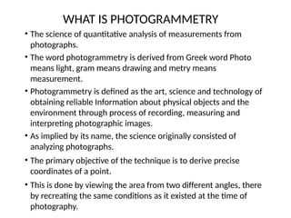
WHAT IS PHOTOGRAMMETRY
•The science of quantitative analysis of measurements from
photographs.
• The word photogrammetry is derived from Greek word Photo
means light, gram means drawing and metry means
measurement.
• Photogrammetry is defined as the art, science and technology of
obtaining reliable Information about physical objects and the
environment through process of recording, measuring and
interpreting photographic images.
• As implied by its name, the science originally consisted of
analyzing photographs.
• The primary objective of the technique is to derive precise
coordinates of a point.
• This is done by viewing the area from two different angles, there
by recreating the same conditions as it existed at the time of
photography.
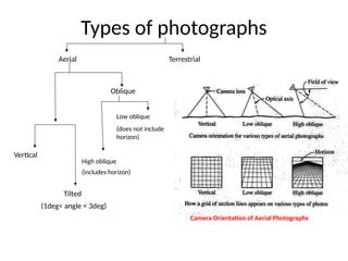
Photographs can beclassified as
– On the basis of Camera system used for
photography,
• Digital
• Analogue
– On the basis of platform used for photography,
• Terrestrial
• Aerial
Photographs
5.
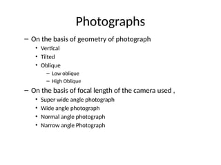
– On thebasis of geometry of photograph
• Vertical
• Tilted
• Oblique
– Low oblique
– High Oblique
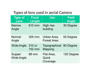
– On the basis of focal length of the camera used ,
• Super wide angle photograph
• Wide angle photograph
• Normal angle photograph
• Narrow angle Photograph
Photographs
6.
Photogrammetry
• Based onhistorical development,
Photogrammetry can be classified
– Analogue Photogrammetry
– Analytical Photogrammetry
– Digital Photogrammetry
7.
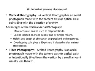
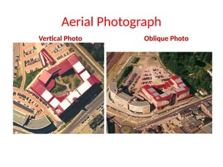
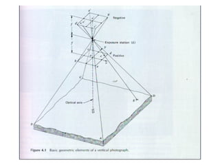
On the basisof geometry of photograph
• Vertical Photography: - A vertical Photograph is an aerial
photograph made with the camera axis (or optical axis)
coinciding with the direction of gravity.
Advantages of the vertical Aerial Photograph
– More accurate, can be used as map substitute.
– Can be located on maps quickly and by simple means.
– Height and depth of object can be perceived and measured.
– Overlapping pair gives a 3D picture if viewed under a mirror
stereoscope.
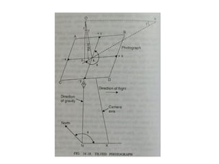
• Tilted Photography: - A tilted Photography is an aerial
photograph made with the camera axis (or optical axis)
unintentionally tilted from the vertical by a small amount
usually less than 30
.
8.
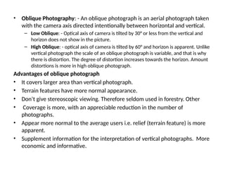
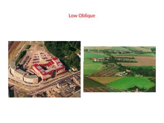
• Oblique Photography:- An oblique photograph is an aerial photograph taken
with the camera axis directed intentionally between horizontal and vertical.
– Low Oblique: - Optical axis of camera is tilted by 30° or less from the vertical and
horizon does not show in the picture.
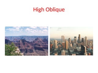
– High Oblique: - optical axis of camera is tilted by 60° and horizon is apparent. Unlike
vertical photograph the scale of an oblique photograph is variable, and that is why
there is distortion. The degree of distortion increases towards the horizon. Amount
distortions is more in high oblique photograph.
Advantages of oblique photograph
• It covers larger area than vertical photograph.
• Terrain features have more normal appearance.
• Don’t give stereoscopic viewing. Therefore seldom used in forestry. Other
• Coverage is more, with an appreciable reduction in the number of
photographs.
• Appear more normal to the average users i.e. relief (terrain feature) is more
apparent.
• Supplement information for the interpretation of vertical photographs. More
economic and informative.
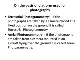
On the basisof platform used for
photography
• Terrestrial Photogrammetry: - If the
photographs are taken by a camera placed at a
fixed position on the ground it is called
Terrestrial Photogrammetry.
• Aerial Photogrammetry: - If the photographs
are taken from a camera mounted in an
aircraft flying over the ground it is called aerial
Photogrammetry.
15.
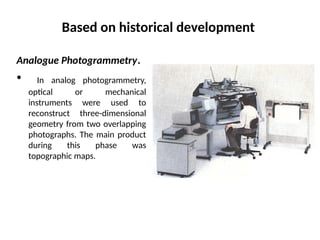
Based on historicaldevelopment
Analogue Photogrammetry.
• In analog photogrammetry,
optical or mechanical
instruments were used to
reconstruct three-dimensional
geometry from two overlapping
photographs. The main product
during this phase was
topographic maps.
16.
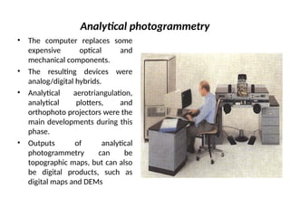
Analytical photogrammetry
• Thecomputer replaces some
expensive optical and
mechanical components.
• The resulting devices were
analog/digital hybrids.
• Analytical aerotriangulation,
analytical plotters, and
orthophoto projectors were the
main developments during this
phase.
• Outputs of analytical
photogrammetry can be
topographic maps, but can also
be digital products, such as
digital maps and DEMs
17.
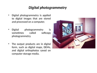
Digital photogrammetry
• Digitalphotogrammetry is applied
to digital images that are stored
and processed on a computer.
• Digital photogrammetry is
sometimes called softcopy
photogrammetry.
• The output products are in digital
form, such as digital maps, DEMs,
and digital orthophotos saved on
computer storage media.
18.
Principle of Photogrammetry
•Theprinciple of photogrammetry is exactly similar to
that of plane table surveying i.e. if the directions of
same objects photographed from two extremities of
measured base are known, their position can be
located by intersection of two rays to the same object.
• Intersecting lines in space are used to compute the
location of a point in all three dimensions.
• In order to triangulate a set of points one must also
know the camera position and orientation for all the
pictures in the set. A process called Resection does this.
19.
Projection and theproperties of Orthogonal
and Perspective Projections
• A perspective projection is the one produced by
straight lines radiating from a common point
and passing through point on the sphere to the
plane of projection. A photograph is a
perspective projection.
• Orthogonal projection is produced on a plane by
projecting the ground points through straight
lines perpendicular to the plane. Plan of the
ground or map is an orthogonal projection.
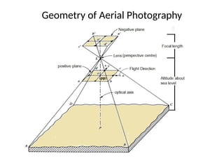
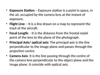
• Exposure Station:- Exposure station is a point in space, in
the air, occupied by the camera lens at the instant of
exposure.
• Flight Line: - It is a line drawn on a map to represent the
track of the aircraft.
• Focal Length: - It is the distance from the frontal nodal
point of the lens to the plane of the photograph.
• Principal Axis/ optical axis: The principal axis is the line
perpendicular to the image plane and passes through the
projection centre.
• Camera Axis: It is the line passing through the centre of
the camera lens perpendicular to the object plane and the
image plane. It coincide with optical axis.
25.
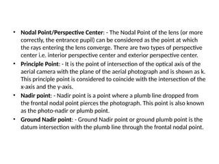
• Nodal Point/PerspectiveCenter: - The Nodal Point of the lens (or more
correctly, the entrance pupil) can be considered as the point at which
the rays entering the lens converge. There are two types of perspective
center i.e. interior perspective center and exterior perspective center.
• Principle Point: - It is the point of intersection of the optical axis of the
aerial camera with the plane of the aerial photograph and is shown as k.
This principle point is considered to coincide with the intersection of the
x-axis and the y-axis.
• Nadir point: - Nadir point is a point where a plumb line dropped from
the frontal nodal point pierces the photograph. This point is also known
as the photo-nadir or plumb point.
• Ground Nadir point: - Ground Nadir point or ground plumb point is the
datum intersection with the plumb line through the frontal nodal point.
26.
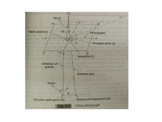
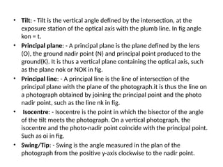
• Tilt: -Tilt is the vertical angle defined by the intersection, at the
exposure station of the optical axis with the plumb line. In fig angle
kon = t.
• Principal plane: - A principal plane is the plane defined by the lens
(O), the ground nadir point (N) and principal point produced to the
ground(K). It is thus a vertical plane containing the optical axis, such
as the plane nok or NOK in fig.
• Principal line: - A principal line is the line of intersection of the
principal plane with the plane of the photograph.it is thus the line on
a photograph obtained by joining the principal point and the photo
nadir point, such as the line nk in fig.
• Isocentre: - Isocentre is the point in which the bisector of the angle
of the tilt meets the photograph. On a vertical photograph, the
isocentre and the photo-nadir point coincide with the principal point.
Such as oi in fig.
• Swing/Tip: - Swing is the angle measured in the plan of the
photograph from the positive y-axis clockwise to the nadir point.
27.
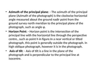
• Azimuth ofthe principal plane: - The azimuth of the principal
plane (Azimuth of the photograph) is the clockwise horizontal
angle measured about the ground nadir point from the
ground survey north meridian to the principal plane of the
photograph, such as angle φ.
• Horizon Point: - Horizon point is the intersection of the
principal line with the horizontal line through the perspective
centre., such as point h in figure.In a near vertical or tilted
photograph, this point is generally outside the photograph. In
high oblique photograph, however it is in the photograph.
• Axis of tilt: - Axis of tilt is a line in the plane of the
photograph and is perpendicular to the principal line at
isocentre.
28.
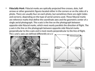
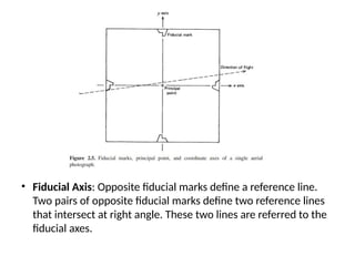
• Fiducially Mark:Fiducial marks are optically projected fine crosses, dots, half
arrows or other geometric figures located either in the corners or on the sides of a
photo. There are usually four on each photo, but sometimes there are eight (sides
and corners), depending on the type of aerial camera used. These fiducial marks
are reference marks that define the coordinate axes and the geometric center of a
single aerial photograph. The x-axis is the line on the photograph between
opposite-side fiducial marks, which most nearly parallels the direction of flight. The
y-axis is the line on the photograph between opposite-side fiducial marks
perpendicular to the x-axis and is most nearly perpendicular to the line of flight.
The x and y axes are defined differently on a stereoscopic pair of aerial photos.
29.
• Fiducial Axis:Opposite fiducial marks define a reference line.
Two pairs of opposite fiducial marks define two reference lines
that intersect at right angle. These two lines are referred to the
fiducial axes.
30.
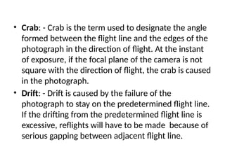
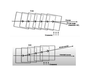
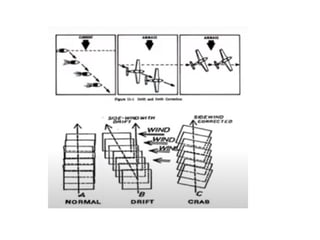
• Crab: -Crab is the term used to designate the angle
formed between the flight line and the edges of the
photograph in the direction of flight. At the instant
of exposure, if the focal plane of the camera is not
square with the direction of flight, the crab is caused
in the photograph.
• Drift: - Drift is caused by the failure of the
photograph to stay on the predetermined flight line.
If the drifting from the predetermined flight line is
excessive, reflights will have to be made because of
serious gapping between adjacent flight line.
33.
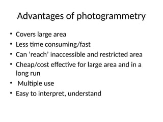
Advantages of photogrammetry
•Covers large area
• Less time consuming/fast
• Can ‘reach’ inaccessible and restricted area
• Cheap/cost effective for large area and in a
long run
• Multiple use
• Easy to interpret, understand
34.
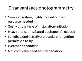
Disadvantages photogrammetry
• Complexsystem, highly trained human
resource needed
• Costly at the time of installation/initiation
• Heavy and sophisticated equipment's needed
• Lengthy administrative procedure for getting
permission to fly
• Weather dependent
• Not complete/need field verification
35.
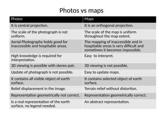
Photos vs maps
PhotosMaps
It is central projection. It is an orthogonal projection.
The scale of the photograph is not
uniform.
The scale of the map is uniform
throughout the map extent.
Aerial Photography holds good for
inaccessible and hospitable areas.
The mapping of inaccessible and in
hospitable areas is very difficult and
sometimes it becomes impossible.
High knowledge is required for
interpretation.
Easy to interpret.
3D viewing is possible with stereo pair. 3D viewing is not possible.
Update of photograph is not possible. Easy to update maps.
It contains all visible object of earth
surface.
It contains selected object of earth
surface.
Relief displacement in the image. Terrain relief without distortion.
Representation geometrically not correct. Representation geometrically correct.
Is a real representation of the earth
surface, no legend needed.
An abstract representation.
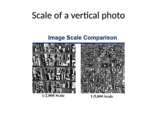
36.
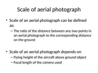
Scale of aerialphotograph
• Scale of an aerial photograph can be defined
as:
– The ratio of the distance between any two points in
an aerial photograph to the corresponding distance
on the ground
• Scale of an aerial photograph depends on
– Flying height of the aircraft above ground object
– Focal length of the camera used
37.
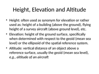
Height, Elevation andAltitude
• Height: often used as synonym for elevation or rather
used as: height of a building (above the ground), flying
height of a survey aircraft (above ground level), etc.
• Elevation: height of the ground surface, specifically
when determined with respect to the geoid (mean sea
level) or the ellipsoid of the spatial reference system.
• Altitude: vertical distance of an object above a
reference surface, usually the geoid (mean sea level),
e.g., altitude of an aircraft
Scale and groundcoverage
• Larger the scale: smaller the ground coverage
• Larger the scale: larger the object size on
photograph, easy to recognize the details
• Smaller the scale: larger the ground coverage
• Smaller the scale: smaller the object size on
photograph, difficult to recognize the details
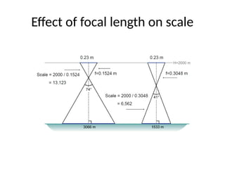
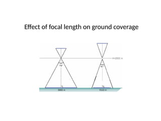
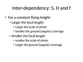
Inter-dependency: S, Hand f
• For a constant flying height:
– Larger the focal length:
• Larger the scale of photo
• Smaller the ground (angular) coverage
– Smaller the focal length:
• smaller the scale of photo
• Larger the ground (angular) coverage
43.
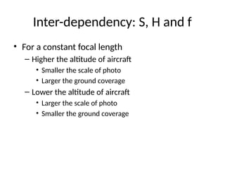
• For aconstant focal length
– Higher the altitude of aircraft
• Smaller the scale of photo
• Larger the ground coverage
– Lower the altitude of aircraft
• Larger the scale of photo
• Smaller the ground coverage
Inter-dependency: S, H and f
44.
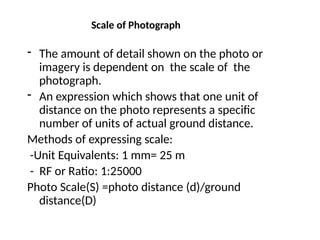
Scale of Photograph
-The amount of detail shown on the photo or
imagery is dependent on the scale of the
photograph.
- An expression which shows that one unit of
distance on the photo represents a specific
number of units of actual ground distance.
Methods of expressing scale:
-Unit Equivalents: 1 mm= 25 m
- RF or Ratio: 1:25000
Photo Scale(S) =photo distance (d)/ground
distance(D)
45.
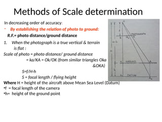
Methods of Scaledetermination
In decreasing order of accuracy:
- By establishing the relation of photo to ground:
R.F.= photo distance/ground distance
1. When the photograph is a true vertical & terrain
is flat :
Scale of photo = photo distance/ ground distance
= ka/KA = Ok/OK (from similar triangles Oka
&OKA)
S=f/H-h
S = focal length / flying height
Where H = height of the aircraft above Mean Sea Level (Datum)
•f = focal length of the camera
•h= height of the ground point
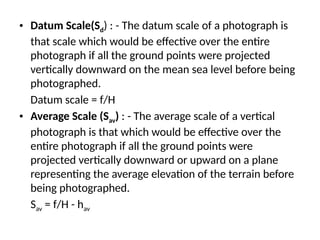
• Datum Scale(Sd): - The datum scale of a photograph is
that scale which would be effective over the entire
photograph if all the ground points were projected
vertically downward on the mean sea level before being
photographed.
Datum scale = f/H
• Average Scale (Sav) : - The average scale of a vertical
photograph is that which would be effective over the
entire photograph if all the ground points were
projected vertically downward or upward on a plane
representing the average elevation of the terrain before
being photographed.
Sav = f/H - hav
48.
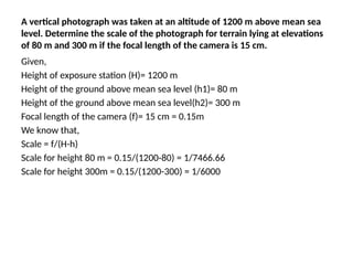
A vertical photographwas taken at an altitude of 1200 m above mean sea
level. Determine the scale of the photograph for terrain lying at elevations
of 80 m and 300 m if the focal length of the camera is 15 cm.
Given,
Height of exposure station (H)= 1200 m
Height of the ground above mean sea level (h1)= 80 m
Height of the ground above mean sea level(h2)= 300 m
Focal length of the camera (f)= 15 cm = 0.15m
We know that,
Scale = f/(H-h)
Scale for height 80 m = 0.15/(1200-80) = 1/7466.66
Scale for height 300m = 0.15/(1200-300) = 1/6000
49.
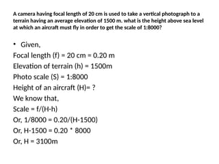
A camera havingfocal length of 20 cm is used to take a vertical photograph to a
terrain having an average elevation of 1500 m. what is the height above sea level
at which an aircraft must fly in order to get the scale of 1:8000?
• Given,
Focal length (f) = 20 cm = 0.20 m
Elevation of terrain (h) = 1500m
Photo scale (S) = 1:8000
Height of an aircraft (H)= ?
We know that,
Scale = f/(H-h)
Or, 1/8000 = 0.20/(H-1500)
Or, H-1500 = 0.20 * 8000
Or, H = 3100m
50.
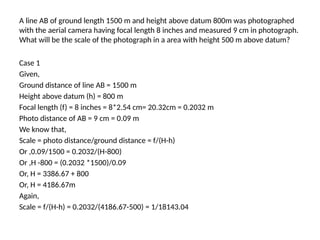
A line ABof ground length 1500 m and height above datum 800m was photographed
with the aerial camera having focal length 8 inches and measured 9 cm in photograph.
What will be the scale of the photograph in a area with height 500 m above datum?
Case 1
Given,
Ground distance of line AB = 1500 m
Height above datum (h) = 800 m
Focal length (f) = 8 inches = 8*2.54 cm= 20.32cm = 0.2032 m
Photo distance of AB = 9 cm = 0.09 m
We know that,
Scale = photo distance/ground distance = f/(H-h)
Or ,0.09/1500 = 0.2032/(H-800)
Or ,H -800 = (0.2032 *1500)/0.09
Or, H = 3386.67 + 800
Or, H = 4186.67m
Again,
Scale = f/(H-h) = 0.2032/(4186.67-500) = 1/18143.04
51.
Distortion and Displacementin Aerial
Photograph
• Distortion is any shift in the position of an
image on a photograph that alters the
perspective characteristics of the image.
• Displacement is any shift in the position of an
image on a photograph that does not alter the
perspective characteristics of the photograph.
52.
• Types ofDistortions:
– Film deformation
– Lens and Filter Distortion
– Image Motion
– Atmospheric Refraction of Light Rays
• Types of displacement
– Curvature of the Earth
– Relief
– Tilt
53.
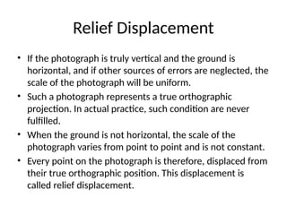
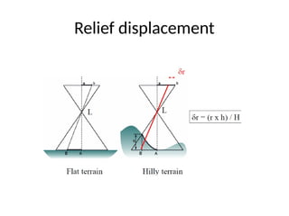
Relief Displacement
• Ifthe photograph is truly vertical and the ground is
horizontal, and if other sources of errors are neglected, the
scale of the photograph will be uniform.
• Such a photograph represents a true orthographic
projection. In actual practice, such condition are never
fulfilled.
• When the ground is not horizontal, the scale of the
photograph varies from point to point and is not constant.
• Every point on the photograph is therefore, displaced from
their true orthographic position. This displacement is
called relief displacement.
54.
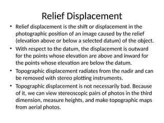
Relief Displacement
• Reliefdisplacement is the shift or displacement in the
photographic position of an image caused by the relief
(elevation above or below a selected datum) of the object.
• With respect to the datum, the displacement is outward
for the points whose elevation are above and inward for
the points whose elevation are below the datum.
• Topographic displacement radiates from the nadir and can
be removed with stereo plotting instruments.
• Topographic displacement is not necessarily bad. Because
of it, we can view stereoscopic pairs of photos in the third
dimension, measure heights, and make topographic maps
from aerial photos.
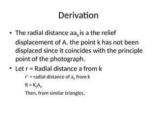
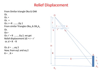
Derivation
• The radialdistance aa0 is a the relief
displacement of A. the point k has not been
displaced since it coincides with the principle
point of the photograph.
• Let r = Radial distance a from k
r’ = radial distance of a0 from k
R = K0A0
Then, from similar triangles,
58.
Relief Displacement
O
A
A0
K0
a
a0
k
K
f
H
h
r
r’
R
From Similartriangle Oka & OAK
Or,
Or, =
Or, =
Or, r = R ………Eq 1
From similar Triangles Okao & OKoAo
Or,
Or,=
Or, r’ = R ………Eq 2, we get
Relief displacement (d) = r – r’
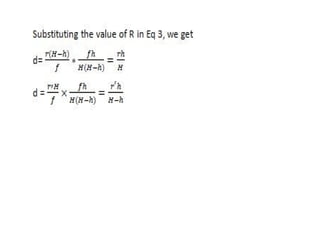
or, d = R - R
Or, d = ….eq 3
Now, from eq1 and eq 2
R = , R =
60.
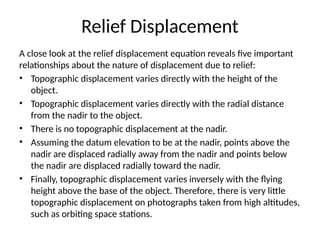
Relief Displacement
A closelook at the relief displacement equation reveals five important
relationships about the nature of displacement due to relief:
• Topographic displacement varies directly with the height of the
object.
• Topographic displacement varies directly with the radial distance
from the nadir to the object.
• There is no topographic displacement at the nadir.
• Assuming the datum elevation to be at the nadir, points above the
nadir are displaced radially away from the nadir and points below
the nadir are displaced radially toward the nadir.
• Finally, topographic displacement varies inversely with the flying
height above the base of the object. Therefore, there is very little
topographic displacement on photographs taken from high altitudes,
such as orbiting space stations.
61.
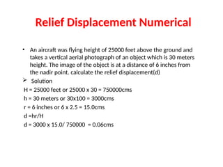
Relief Displacement Numerical
•An aircraft was flying height of 25000 feet above the ground and
takes a vertical aerial photograph of an object which is 30 meters
height. The image of the object is at a distance of 6 inches from
the nadir point. calculate the relief displacement(d)
Solution
H = 25000 feet or 25000 x 30 = 750000cms
h = 30 meters or 30x100 = 3000cms
r = 6 inches or 6 x 2.5 = 15.0cms
d =hr/H
d = 3000 x 15.0/ 750000 = 0.06cms
62.
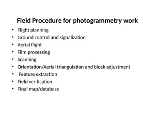
Field Procedure forphotogrammetry work
• Flight planning
• Ground control and signalization
• Aerial flight
• Film processing
• Scanning
• Orientation/Aerial triangulation and block adjustment
• Feature extraction
• Field verification
• Final map/database
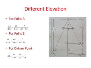
63.
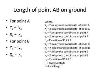
Length of pointAB on ground
• For point A
• Ya = ya
• Xa = xa
• For point B
• Yb = yb
• Xb = xb
Where,
Ya = Y axis ground coordinate of point A
Xa = X axis ground coordinate of point A
ya = Y axis photo coordinate of point A
ya = X axis photo coordinate of point A
ha = Elevation of Point A
Yb = Y axis ground coordinate of point B
Xb = X axis ground coordinate of point B
yb = Y axis photo coordinate of point B
xb = X axis photo coordinate of point B
hb = Elevation of Point B
H = Flying Altitude
f = focal length
64.
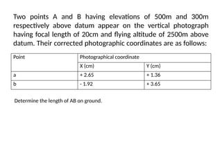
Two points Aand B having elevations of 500m and 300m
respectively above datum appear on the vertical photograph
having focal length of 20cm and flying altitude of 2500m above
datum. Their corrected photographic coordinates are as follows:
Point Photographical coordinate
X (cm) Y (cm)
a + 2.65 + 1.36
b - 1.92 + 3.65
Determine the length of AB on ground.
65.
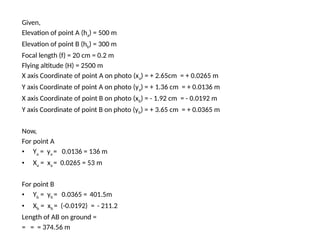
Given,
Elevation of pointA (ha) = 500 m
Elevation of point B (hb) = 300 m
Focal length (f) = 20 cm = 0.2 m
Flying altitude (H) = 2500 m
X axis Coordinate of point A on photo (xa) = + 2.65cm = + 0.0265 m
Y axis Coordinate of point A on photo (ya) = + 1.36 cm = + 0.0136 m
X axis Coordinate of point B on photo (xb) = - 1.92 cm = - 0.0192 m
Y axis Coordinate of point B on photo (yb) = + 3.65 cm = + 0.0365 m
Now,
For point A
• Ya = ya = 0.0136 = 136 m
• Xa = xa = 0.0265 = 53 m
For point B
• Yb = yb = 0.0365 = 401.5m
• Xb = xb = (-0.0192) = - 211.2
Length of AB on ground =
= = = 374.56 m
66.
UAV Surveying
• Dronebased surveying (or mapping) uses
unmanned aerial vehicles (UAVs) to collect
spatial data from air.
• Instead of using ground crews to measure the
dimensions of a particular area of the earth’s
surface, drones equipped with 3D laser scanners
and cameras can collect spatial data from the air.
• That data is used to produce a finished map or
3D model.
67.
Components of UAV
•Airframe: The physical structure of the UAV, available as fixed-
wing (for large areas) or rotary-wing (for detailed surveys).
• Propulsion System: Includes motors, propellers, and batteries
to enable flight and movement.
• Flight Controller: The "brain" that stabilizes and controls flight
dynamics.
• Navigation System: Features GPS, IMU, and RTK for accurate
positioning and flight paths.
• Payload: Survey-specific equipment like cameras (RGB,
multispectral), LiDAR, or thermal sensors.
• Communication System: Ensures real-time control and data
transfer between the UAV and the ground station.
68.
Components of UAV
•Ground Control Station (GCS): Operator interface for
programming flight paths and monitoring operations.
• Sensors: Includes obstacle avoidance, barometers, and
compasses for stability and safety.
• Power Management: Batteries and monitoring systems
ensure sufficient power for missions.
• Software: Flight planning and data processing software
convert raw data into usable outputs (e.g., maps, 3D models).
• Landing Gear: Protects the UAV during takeoff and landing.
• Environmental Protection: Shields the UAV from weather,
dust, and temperature extremes.
69.
Data types andData processing software
• UAV (drone) surveys generate diverse datasets
that can be processed using specialized
software to create accurate maps, models,
and analyses.
• Aerial imagery is captured by UAV which is
raster data type.
70.
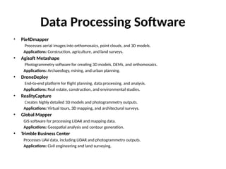
Data Processing Software
•Pix4Dmapper
Processes aerial images into orthomosaics, point clouds, and 3D models.
Applications: Construction, agriculture, and land surveys.
• Agisoft Metashape
Photogrammetry software for creating 3D models, DEMs, and orthomosaics.
Applications: Archaeology, mining, and urban planning.
• DroneDeploy
End-to-end platform for flight planning, data processing, and analysis.
Applications: Real estate, construction, and environmental studies.
• RealityCapture
Creates highly detailed 3D models and photogrammetry outputs.
Applications: Virtual tours, 3D mapping, and architectural surveys.
• Global Mapper
GIS software for processing LiDAR and mapping data.
Applications: Geospatial analysis and contour generation.
• Trimble Business Center
Processes UAV data, including LiDAR and photogrammetry outputs.
Applications: Civil engineering and land surveying.