Downloaded 671 times
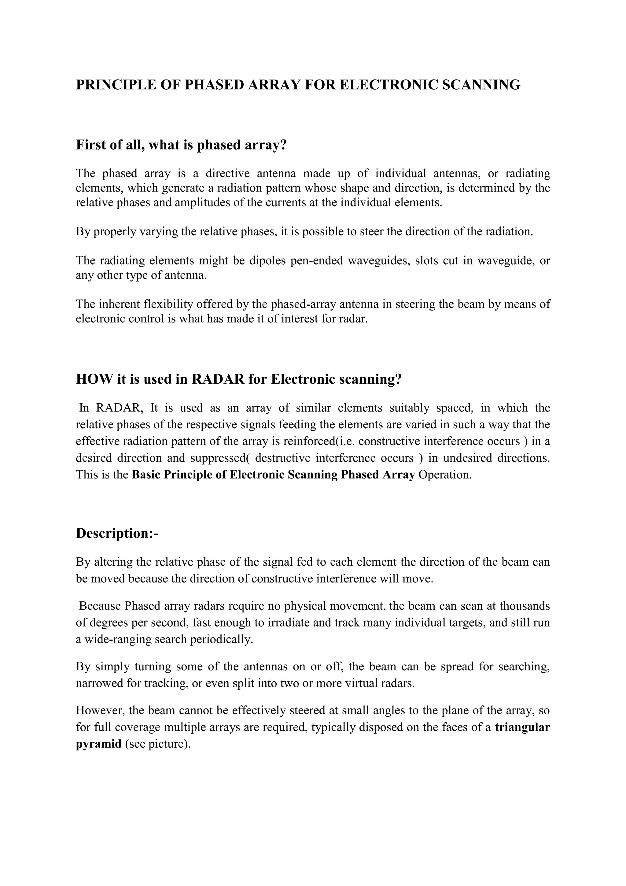
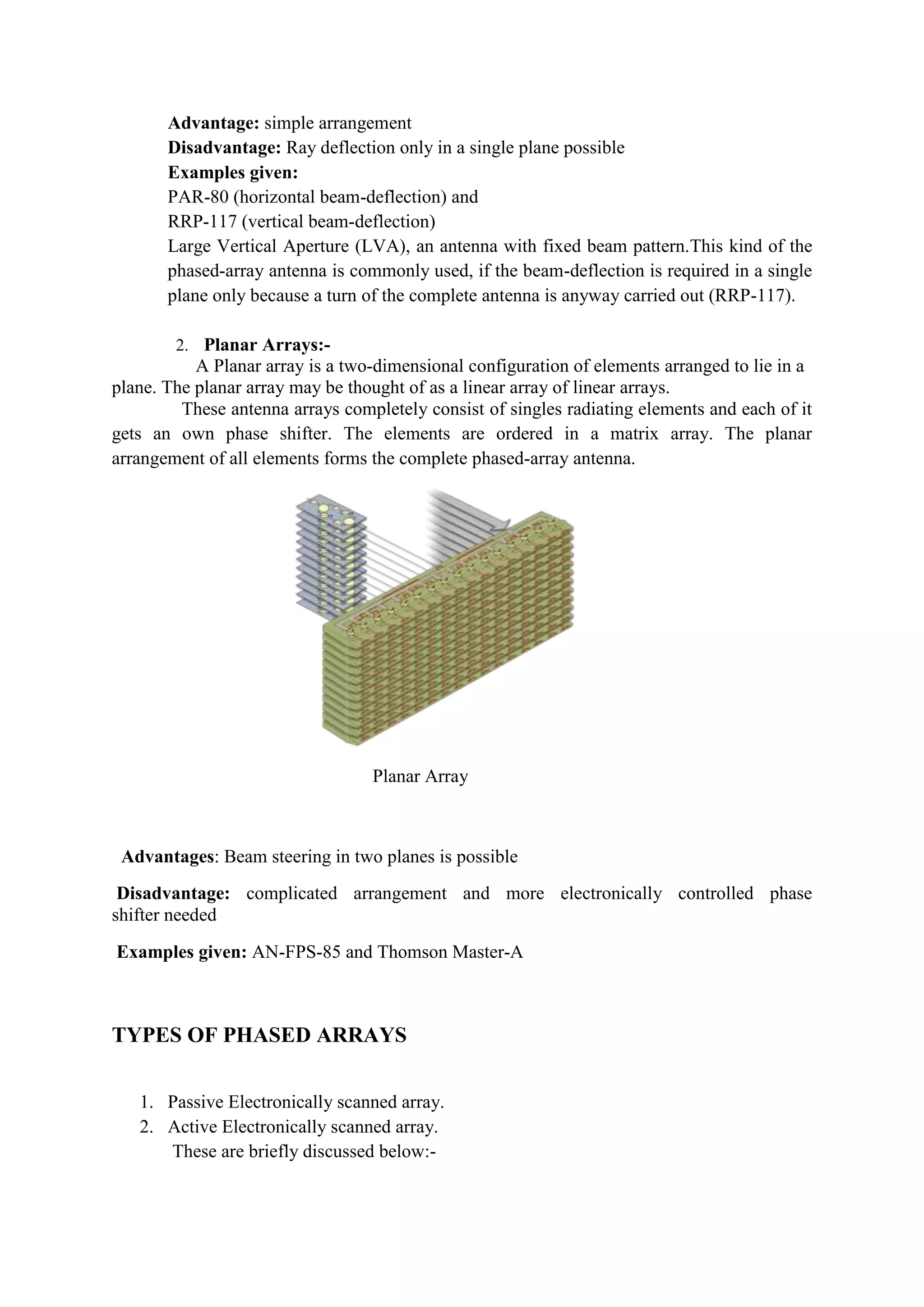

Phased array antennas use interference between signals from multiple radiating elements to electronically steer antenna beams without moving parts. By adjusting the relative phases of the signals, the main beam direction can be changed. This allows for rapid electronic scanning to search for and track targets. Phased arrays are used in radar systems for military aircraft and ships where they provide advantages over mechanically scanned antennas, allowing detection of stealthy targets. Common arrangements include linear arrays that scan in one plane and planar arrays that provide two-dimensional beam steering.


![3_Antenna Array [Modlue 4] (1).pdf](https://cdn.slidesharecdn.com/ss_thumbnails/3antennaarraymodlue41-220419112111-thumbnail.jpg?width=640&height=640&fit=bounds)


