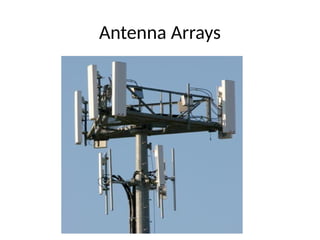
Introduction
• An antenna,when individually can radiate an amount of energy,
in a particular direction, resulting in better transmission.
• If few more elements are added it, to produce more efficient
output.
• It is exactly this idea, which led to the invention of Antenna
arrays.
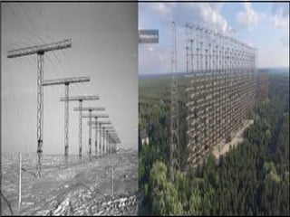
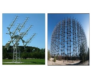
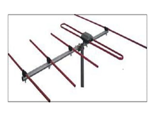
• An antenna array can be better understood by observing the
following images. Observe how the antenna arrays are
connected.
4.
• An antennaarray is a radiating system, which
consists of individual radiators and elements.
• Each of this radiator, while functioning has its
own induction field.
• The elements are placed so closely that each
one lies in the neighboring one’s induction
field.
• Therefore, the radiation pattern produced by
them, would be the vector sum of the
individual ones.
• The following image shows another example
of an antenna array.
6.
• The spacingbetween the elements and the
length of the elements according to the
wavelength are also to be kept in mind while
designing these antennas.
• The antennas radiate individually and while in
array, the radiation of all the elements sum up,
to form the radiation beam, which has high
gain, high directivity and better performance,
with minimum losses.
7.
Advantages
• The signalstrength increases
• High directivity is obtained
• Minor lobes are reduced much
• High Signal-to-noise ratio is achieved
• High gain is obtained
• Power wastage is reduced
• Better performance is obtained
Applications
• Used insatellite communications
• Used in wireless communications
• Used in military radar communications
• Used in the astronomical study
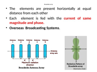
Broadside array
• Theelements are present horizontally at equal
distance from each other
• Each element is fed with the current of same
magnitude and phase.
• Overseas Broadcasting Systems.
12.
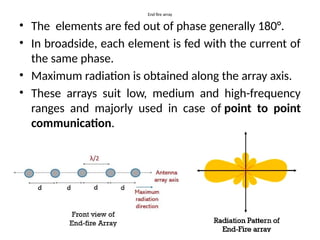
End fire array
•The elements are fed out of phase generally 180°.
• In broadside, each element is fed with the current of
the same phase.
• Maximum radiation is obtained along the array axis.
• These arrays suit low, medium and high-frequency
ranges and majorly used in case of point to point
communication.
13.
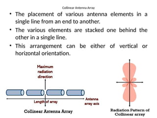
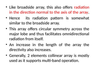
Collinear Antenna Array
•The placement of various antenna elements in a
single line from an end to another.
• The various elements are stacked one behind the
other in a single line.
• This arrangement can be either of vertical or
horizontal orientation.
14.
• Like broadsidearray, this also offers radiation
in the direction normal to the axis of the array.
• Hence its radiation pattern is somewhat
similar to the broadside array.
• This array offers circular symmetry across the
major lobe and thus facilitates omnidirectional
radiation from itself.
• An increase in the length of the array the
directivity also increases.
• Generally, 2 elements collinear array is mostly
used as it supports multi-band operation.
15.
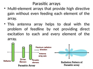
Parasitic arrays
• Multi-elementarrays that provide high directive
gain without even feeding each element of the
array.
• This antenna array helps to deal with the
problem of feedline by not providing direct
excitation to each and every element of the
array.
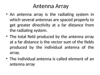
Antenna Array
• Anantenna array is the radiating system in
which several antennas are spaced properly to
get greater directivity at a far distance from
the radiating system.
• The total field produced by the antenna array
at a far distance is the vector sum of the fields
produced by the individual antenna of the
array.
• The individual antenna is called element of an
antenna array
20.
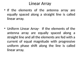
Linear Array
• Ifthe elements of the antenna array are
equally spaced along a straight line is called
linear array.
• Uniform Linear Array- If the elements of the
antenna array are equally spaced along a
straight line and all the elements are fed with a
current of equal magnitude with progressive
uniform phase shift along the line is called
linear array.
21.
Array of PointSources
• Isotropic radiators are called as point sources
because it occupies zero volume.
• If number of point sources are more, then the
analysis becomes complicated and time
consuming.


![3_Antenna Array [Modlue 4] (1).pdf](https://cdn.slidesharecdn.com/ss_thumbnails/3antennaarraymodlue41-220419112111-thumbnail.jpg?width=640&height=640&fit=bounds)


