Antenna Arrays
• Forsome applications single element antennas are
unable to meet the gain or radiation pattern
requirements.
• So, the concept of an antenna array was first introduced
in military applications in the 1940‟s .
• This development was significant in wireless
communications as it improved the reception and
transmission patterns of antennas used in these systems.
• “A Radiating System Consisting of several spaced and properly
phased radiators.”
2
Krishna Chaitanya. P Vignan’s University
3.
Antenna Arrays
• Thearray also enabled the antenna system to be
electronically steered – to receive or transmit
information primarily from a particular direction
without mechanically moving the structure.
• Multiple antenna elements
• Current of different amplitude and phase
• Total pattern is the sum of individual radiation
3
Krishna Chaitanya. P Vignan’s University
4.
Advantages of usingantenna
arrays
• They can provide a high gain (array gain) by using
simple antenna elements.
• They can provide the capability of a steerable beam,
“steer” the array so that it is most sensitive in a
particular direction
• Cancel out interference from a particular set of
directions
• Determine the direction of arrival of the incoming
signals
4
Krishna Chaitanya. P Vignan’s University
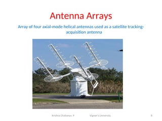
Antenna Arrays
Array offour axial-mode helical antennas used as a satellite tracking-
acquisition antenna
8
Krishna Chaitanya. P Vignan’s University
9.
6 sector sitein CDMA
9
Krishna Chaitanya. P Vignan’s University
10.
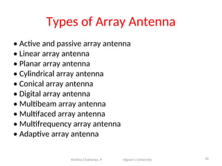
Types of ArrayAntenna
• Active and passive array antenna
• Linear array antenna
• Planar array antenna
• Cylindrical array antenna
• Conical array antenna
• Digital array antenna
• Multibeam array antenna
• Multifaced array antenna
• Multifrequency array antenna
• Adaptive array antenna
10
Krishna Chaitanya. P Vignan’s University
11.
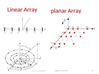
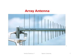
Linear Array
• Consistsof group of identical elements
• Elements placed in 1-D
• Elements placed in specified direction in a straight
line
• Spacing between element may be equal or not
• Used in analysis of directional properties of arrays
11
Krishna Chaitanya. P Vignan’s University
12.
Linear Array
• Designof antenna is practical and simpler
• Individual elements may be wire dipoles, loops,
apertures or any other type
• Total field = vector superposition of field radiated by
individual elements
• AFn(normalized) = 1/n[sin(nψ/2) / sin(ψ/2)]
where Afn is the normalized array factor
12
Krishna Chaitanya. P Vignan’s University
Radiation Pattern forArrays
Depends on:
• The type of the individual elements
• Their orientation
• Their position in space
• The amplitude and phase of the current feeding
them
• The total number of elements
14
Krishna Chaitanya. P Vignan’s University
15.
APPLICATIONS
• A phasedarray receiver can be mounted on the top
of a commercial airplane's so that all of the happy
passengers can receive satellite television
• It is also used for weather forecast and tracking
missiles and aircrafts; such as search radar and
tracking radar.
15
Krishna Chaitanya. P Vignan’s University
16.
Classification of Uniformliner arrays
• Broadside Array
• End fire Array
• Collinear Array
• Parasitic Array
16
17.
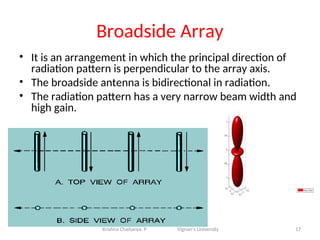
Broadside Array
• Itis an arrangement in which the principal direction of
radiation pattern is perpendicular to the array axis.
• The broadside antenna is bidirectional in radiation.
• The radiation pattern has a very narrow beam width and
high gain.
17
Krishna Chaitanya. P Vignan’s University
18.
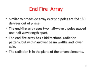
End Fire Array
•Similar to broadside array except dipoles are fed 180
degrees out of phase
• The end-fire array uses two half-wave dipoles spaced
one-half wavelength apart.
• The end-fire array has a bidirectional radiation
pattern, but with narrower beam widths and lower
gain.
• The radiation is in the plane of the driven elements.
18
19.
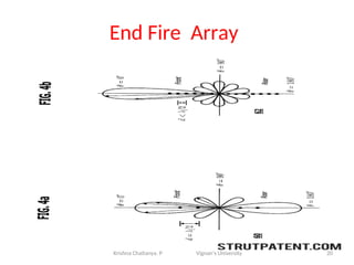
End Fire Array
•A highly unidirectional antenna can be created by
careful selection of the optimal number of elements
with the appropriately related spacing.
• Higher directivity.
• Generally used for reception.
• End-fire antennas. (a) Bidirectional. (b) Unidirectional
19
Krishna Chaitanya. P Vignan’s University
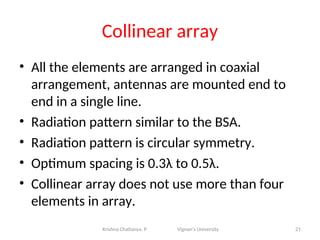
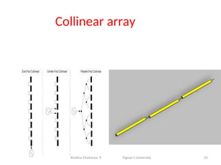
Collinear array
• Allthe elements are arranged in coaxial
arrangement, antennas are mounted end to
end in a single line.
• Radiation pattern similar to the BSA.
• Radiation pattern is circular symmetry.
• Optimum spacing is 0.3λ to 0.5λ.
• Collinear array does not use more than four
elements in array.
21
Krishna Chaitanya. P Vignan’s University
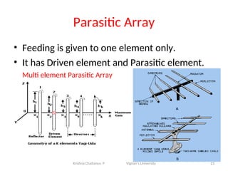
Parasitic Array
• Feedingis given to one element only.
• It has Driven element and Parasitic element.
Multi element Parasitic Array
23
Krishna Chaitanya. P Vignan’s University


![Linear Array
• Design of antenna is practical and simpler
• Individual elements may be wire dipoles, loops,
apertures or any other type
• Total field = vector superposition of field radiated by
individual elements
• AFn(normalized) = 1/n[sin(nψ/2) / sin(ψ/2)]
where Afn is the normalized array factor
12
Krishna Chaitanya. P Vignan’s University](https://image.slidesharecdn.com/antennaarrays-250901171403-c5c45aca/85/Antenna-Arrays-Design-and-Analysis-and-ppt-12-320.jpg)