Downloaded 94 times

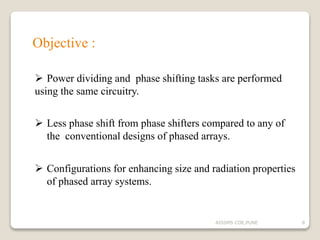
![To reduces the required amount of phase shifting :
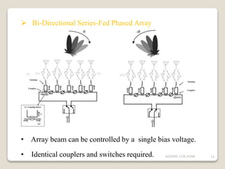
Placing the phase shifters in series rather than in parallel.
arrays can be bi-directionally fed.
1] 2]
3]
4]
15AISSMS COE,PUNE](https://image.slidesharecdn.com/enhancementinphasedarrayantenna-160320133800/85/Enhancement-in-phased-array-antenna-15-320.jpg)
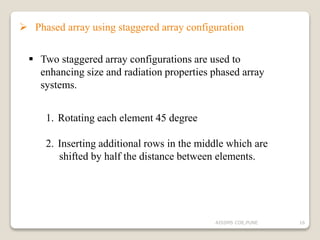
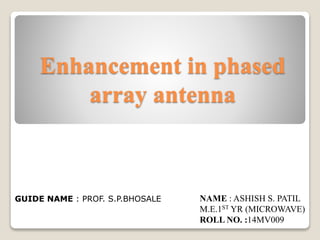
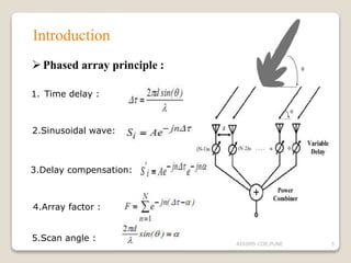
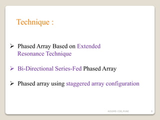
![2] staggered configuration 1
3] staggered configuration 2
1] Regular configuration
17AISSMS COE,PUNE](https://image.slidesharecdn.com/enhancementinphasedarrayantenna-160320133800/85/Enhancement-in-phased-array-antenna-17-320.jpg)
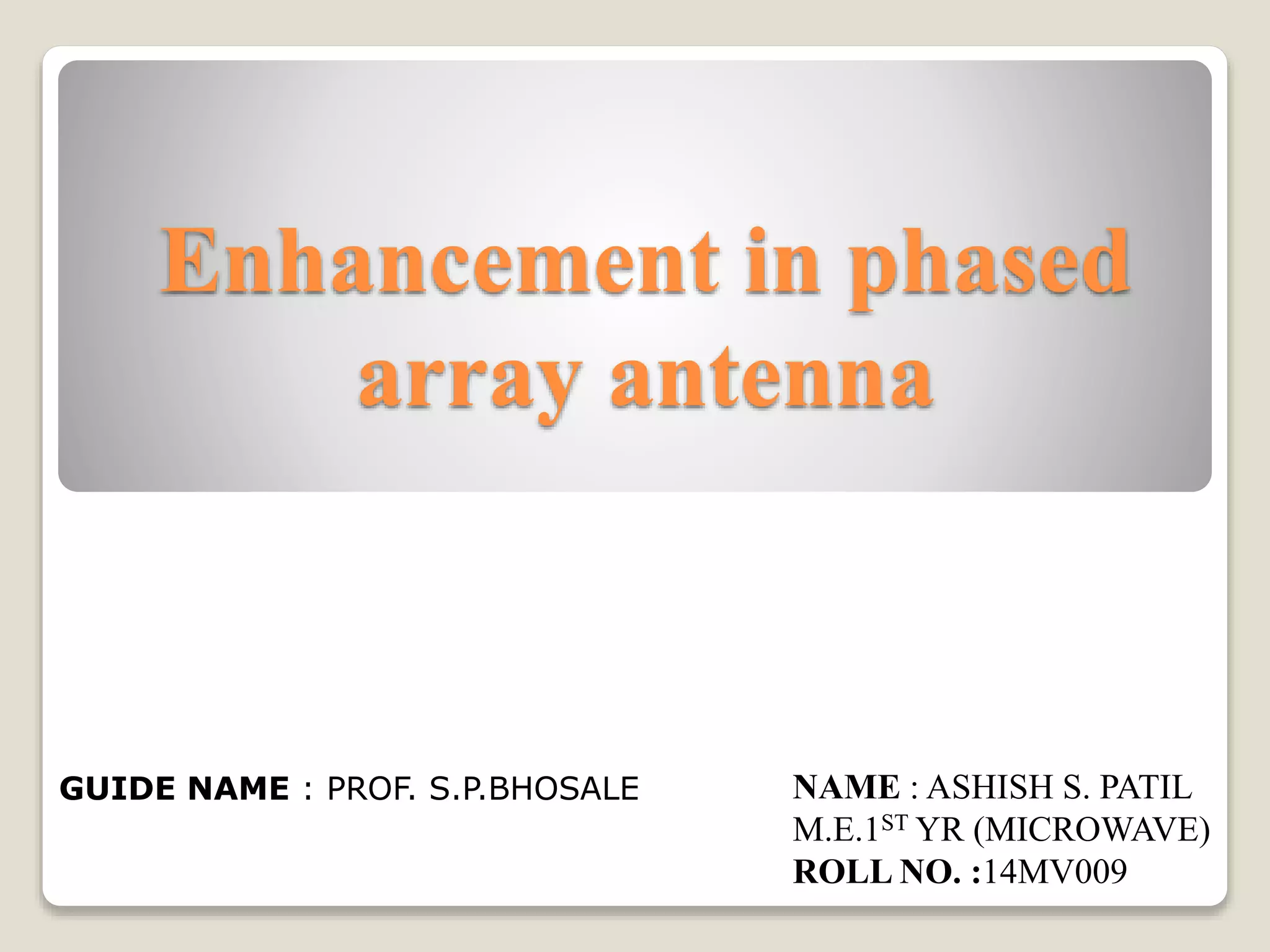
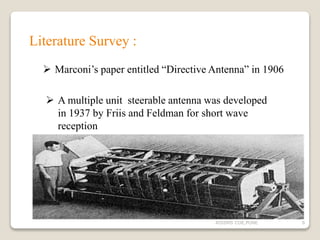
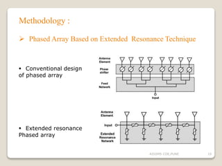
![ Simulation on MATLAB
=N = 20; % Number of elements
=D = 0.5; % Element spacing (m)
=ha = phased.ULA(N,D);
=ViewArray(ha,'Title','Uniform Linear
Array (ULA)')
set(gca,'CameraViewAngle',4.4);
=N = 24; % Number of elements
= R = 1; % Radius (m)
=azang = (0:N-1)*360/N-180;
=ha = phased.ConformalArray(...
'ElementPosition',[R*cosd(azang);
R*sind(azang);zeros(1,N)],...
ElementNormal', [azang;zeros(1,N)]);
= viewArray(ha,'ShowNormals',true,
'Title','Uniform Circular Array (UCA)')
view(0,90)
19AISSMS COE,PUNE](https://image.slidesharecdn.com/enhancementinphasedarrayantenna-160320133800/85/Enhancement-in-phased-array-antenna-19-320.jpg)
![ REFEREANCE
[1] Abdelnasser A. Eldek , “Enhancement of phased array size and radiation
properties using staggered array configuration ”, IEEE Trans.Vol. 39,2013
[2] Danial Ehyaie , “Novel Approaches to the Design of Phased Array Antennas”
Prentice-hall,Inc,2011
[3] Stefan J. Wijnholds, Wim A. van Cappellen and Jan Geralt bij de Vaate ,
“Advances in Phased Array Systems for Radio Astronomy” , IEEE Trans,
Vol . 59,2013
[4] S.L.Karode, “Self-phasing antenna array techniques for mobile communications
applications ”,IEEE Trans, Dec 2000
[5] Ali Tombak and Amir Mortazawi, “Novel Low-Cost Beam-Steering Technique
Based on the Extended-Resonance Power-Dividing Method ”, IEEE Trans,
vol.52,no.2,Feb 2004
[6] Danial Ehyaie , “A 24-GHz Modular Transmit Phased Array”,IEEE vol.59,
no.6,June 2011
[7]www.mathworks.com/R2015/phased antenna array toolbox.html
22AISSMS COE,PUNE](https://image.slidesharecdn.com/enhancementinphasedarrayantenna-160320133800/85/Enhancement-in-phased-array-antenna-22-320.jpg)


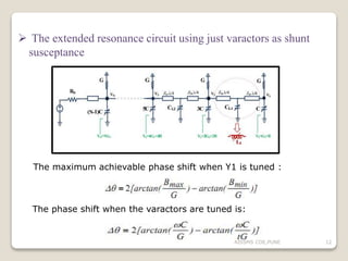
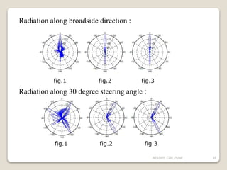
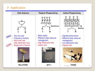
The document discusses advancements in phased array antennas, highlighting techniques such as extended resonance and staggered array configurations to enhance size and radiation properties. It includes a literature survey, objectives for design improvements, and MATLAB simulations for array configurations. Applications mentioned include mobile communications and radio astronomy.