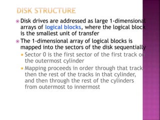
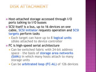
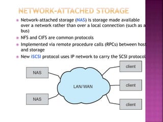
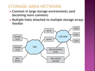
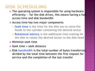
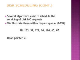
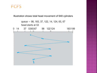
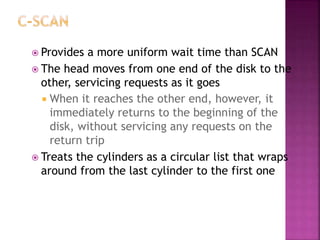
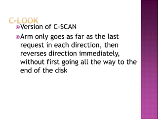
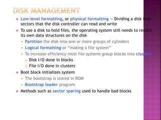
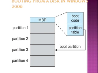
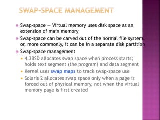
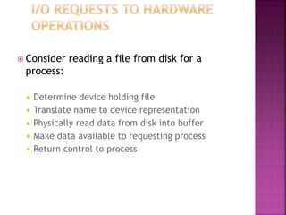
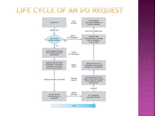
BY
P.GANGA PARAMESHWARI
(14BIT005)
TO
Ms.R.MADHUBALA M.C.A.,
 Disk drives are addressed as large 1-dimensional
arrays of logical blocks, where the logical block
is the smallest unit of transfer
 The 1-dimensional array of logical blocks is
mapped into the sectors of the disk sequentially
 Sector 0 is the first sector of the first track on
the outermost cylinder
 Mapping proceeds in order through that track,
then the rest of the tracks in that cylinder,
and then through the rest of the cylinders
from outermost to innermost
 Host-attached storage accessed through I/O
ports talking to I/O busses
 SCSI itself is a bus, up to 16 devices on one
cable, SCSI initiator requests operation and SCSI
targets perform tasks
 Each target can have up to 8 logical units
(disks attached to device controller
 FC is high-speed serial architecture
 Can be switched fabric with 24-bit address
space – the basis of storage area networks
(SANs) in which many hosts attach to many
storage units
 Can be arbitrated loop (FC-AL) of 126 devices
 Network-attached storage (NAS) is storage made available
over a network rather than over a local connection (such as a
bus)
 NFS and CIFS are common protocols
 Implemented via remote procedure calls (RPCs) between host
and storage
 New iSCSI protocol uses IP network to carry the SCSI protocol
 Common in large storage environments (and
becoming more common)
 Multiple hosts attached to multiple storage arrays -
flexible
 The operating system is responsible for using hardware
efficiently — for the disk drives, this means having a fast
access time and disk bandwidth
 Access time has two major components
 Seek time is the time for the disk are to move the
heads to the cylinder containing the desired sector
 Rotational latency is the additional time waiting for
the disk to rotate the desired sector to the disk head
 Minimize seek time
 Seek time  seek distance
 Disk bandwidth is the total number of bytes transferred,
divided by the total time between the first request for
service and the completion of the last transfer
 Several algorithms exist to schedule the
servicing of disk I/O requests
 We illustrate them with a request queue (0-199)
98, 183, 37, 122, 14, 124, 65, 67
Head pointer 53
Illustration shows total head movement of 640 cylinders
 Selects the request with the minimum seek
time from the current head position
 SSTF scheduling is a form of SJF scheduling;
may cause starvation of some requests
 Illustration shows total head movement of
236 cylinders
 The disk arm starts at one end of the disk,
and moves toward the other end, servicing
requests until it gets to the other end of the
disk, where the head movement is reversed
and servicing continues.
 SCAN algorithm Sometimes called the
elevator algorithm
 Illustration shows total head movement of
208 cylinders
 Provides a more uniform wait time than SCAN
 The head moves from one end of the disk to the
other, servicing requests as it goes
 When it reaches the other end, however, it
immediately returns to the beginning of the
disk, without servicing any requests on the
return trip
 Treats the cylinders as a circular list that wraps
around from the last cylinder to the first one
Version of C-SCAN
Arm only goes as far as the last
request in each direction, then
reverses direction immediately,
without first going all the way to the
end of the disk
 SSTF is common and has a natural appeal
 SCAN and C-SCAN perform better for systems that place
a heavy load on the disk
 Performance depends on the number and types of
requests
 Requests for disk service can be influenced by the file-
allocation method
 The disk-scheduling algorithm should be written as a
separate module of the operating system, allowing it to
be replaced with a different algorithm if necessary
 Either SSTF or LOOK is a reasonable choice for the
default algorithm
 Low-level formatting, or physical formatting — Dividing a disk into
sectors that the disk controller can read and write
 To use a disk to hold files, the operating system still needs to record
its own data structures on the disk
 Partition the disk into one or more groups of cylinders
 Logical formatting or “making a file system”
 To increase efficiency most file systems group blocks into clusters
 Disk I/O done in blocks
 File I/O done in clusters
 Boot block initializes system
 The bootstrap is stored in ROM
 Bootstrap loader program
 Methods such as sector sparing used to handle bad blocks
 Swap-space — Virtual memory uses disk space as an
extension of main memory
 Swap-space can be carved out of the normal file system,
or, more commonly, it can be in a separate disk partition
 Swap-space management
 4.3BSD allocates swap space when process starts;
holds text segment (the program) and data segment
 Kernel uses swap maps to track swap-space use
 Solaris 2 allocates swap space only when a page is
forced out of physical memory, not when the virtual
memory page is first created
 Incredible variety of I/O devices
 Storage
 Transmission
 Human-interface
 Common concepts – signals from I/O devices interface
with computer
 Port – connection point for device
 Bus - daisy chain or shared direct access
 PCI bus common in PCs and servers, PCI Express (PCIe)
 expansion bus connects relatively slow devices
 Controller (host adapter) – electronics that operate port,
bus, device
 Sometimes integrated
 Sometimes separate circuit board (host adapter)
 Contains processor, microcode, private memory, bus controller,
etc
 Some talk to per-device controller with bus controller,
microcode, memory, etc
 I/O instructions control devices
 Devices usually have registers where device
driver places commands, addresses, and data to
write, or read data from registers after
command execution
 Data-in register, data-out register, status register,
control register
 Typically 1-4 bytes, or FIFO buffer
 Devices have addresses, used by
 Direct I/O instructions
 Memory-mapped I/O
 Device data and command registers mapped to processor
address space
 Especially for large address spaces (graphics)
 For each byte of I/O
1. Read busy bit from status register until 0
2. Host sets read or write bit and if write copies data into data-out register
3. Host sets command-ready bit
4. Controller sets busy bit, executes transfer
5. Controller clears busy bit, error bit, command-ready bit when transfer done
 Step 1 is busy-wait cycle to wait for I/O from device
 Reasonable if device is fast
 But inefficient if device slow
 CPU switches to other tasks?
 But if miss a cycle data overwritten / lost
 Polling can happen in 3 instruction cycles
 Read status, logical-and to extract status bit, branch if
not zero
 How to be more efficient if non-zero infrequently?
 CPU Interrupt-request line triggered by I/O device
 Checked by processor after each instruction
 Interrupt handler receives interrupts
 Maskable to ignore or delay some interrupts
 Interrupt vector to dispatch interrupt to correct
handler
 Context switch at start and end
 Based on priority
 Some nonmaskable
 Interrupt chaining if more than one device at same
interrupt number
 Interrupt mechanism also used for exceptions
 Terminate process, crash system due to hardware error
 Page fault executes when memory access error
 System call executes via trap to trigger kernel to
execute request
 Multi-CPU systems can process interrupts
concurrently
 If operating system designed to handle it
 Used for time-sensitive processing, frequent, must
be fast
 Used to avoid programmed I/O (one byte at a time) for large data movement
 Requires DMA controller
 Bypasses CPU to transfer data directly between I/O device and memory
 OS writes DMA command block into memory
 Source and destination addresses
 Read or write mode
 Count of bytes
 Writes location of command block to DMA controller
 Bus mastering of DMA controller – grabs bus from CPU
 Cycle stealing from CPU but still much more efficient
 When done, interrupts to signal completion
 Version that is aware of virtual addresses can be even more efficient - DVMA
 I/O system calls encapsulate device behaviors in
generic classes
 Device-driver layer hides differences among I/O
controllers from kernel
 New devices talking already-implemented protocols
need no extra work
 Each OS has its own I/O subsystem structures and
device driver frameworks
 Devices vary in many dimensions
 Character-stream or block
 Sequential or random-access
 Synchronous or asynchronous (or both)
 Sharable or dedicated
 Speed of operation
 read-write, read only, or write only
 Subtleties of devices handled by device drivers
 Broadly I/O devices can be grouped by the OS
into
 Block I/O
 Character I/O (Stream)
 Memory-mapped file access
 Network sockets
 For direct manipulation of I/O device specific
characteristics, usually an escape / back door
 Unix ioctl() call to send arbitrary bits to a device
control register and data to device data register
 Block devices include disk drives
 Commands include read, write, seek
 Raw I/O, direct I/O, or file-system access
 Memory-mapped file access possible
 File mapped to virtual memory and clusters
brought via demand paging
 DMA
 Character devices include keyboards, mice,
serial ports
 Commands include get(), put()
 Libraries layered on top allow line editing
 Varying enough from block and character to
have own interface
 Linux, Unix, Windows and many others
include socket interface
 Separates network protocol from network
operation
 Includes select() functionality
 Approaches vary widely (pipes, FIFOs,
streams, queues, mailboxes)
 Provide current time, elapsed time, timer
 Normal resolution about 1/60 second
 Some systems provide higher-resolution timers
 Programmable interval timer used for timings,
periodic interrupts
 ioctl() (on UNIX) covers odd aspects of I/O such
as clocks and timers
 Blocking - process suspended until I/O completed
 Easy to use and understand
 Insufficient for some needs
 Nonblocking - I/O call returns as much as available
 User interface, data copy (buffered I/O)
 Implemented via multi-threading
 Returns quickly with count of bytes read or written
 select() to find if data ready then read() or
write() to transfer
 Asynchronous - process runs while I/O executes
 Difficult to use
 I/O subsystem signals process when I/O completed
Synchronous Asynchronous
 Vectored I/O allows one system call to perform
multiple I/O operations
 For example, Unix readve() accepts a vector
of multiple buffers to read into or write from
 This scatter-gather method better than multiple
individual I/O calls
 Decreases context switching and system call overhead
 Some versions provide atomicity
 Avoid for example worry about multiple threads changing
data as reads / writes occurring
 Scheduling
 Some I/O request ordering via per-device queue
 Some OSs try fairness
 Some implement Quality Of Service (i.e. IPQOS)
 Buffering - store data in memory while transferring
between devices
 To cope with device speed mismatch
 To cope with device transfer size mismatch
 To maintain “copy semantics”
 Double buffering – two copies of the data
 Kernel and user
 Varying sizes
 Full / being processed and not-full / being used
 Copy-on-write can be used for efficiency in some cases
 Caching - faster device holding copy of data
 Always just a copy
 Key to performance
 Sometimes combined with buffering
 Spooling - hold output for a device
 If device can serve only one request at a time
 i.e., Printing
 Device reservation - provides exclusive access
to a device
 System calls for allocation and de-allocation
 Watch out for deadlock
 OS can recover from disk read, device
unavailable, transient write failures
 Retry a read or write, for example
 Some systems more advanced – Solaris FMA, AIX
 Track error frequencies, stop using device with
increasing frequency of retry-able errors
 Most return an error number or code when I/O
request fails
 System error logs hold problem reports
 User process may accidentally or purposefully
attempt to disrupt normal operation via illegal
I/O instructions
 All I/O instructions defined to be privileged
 I/O must be performed via system calls
 Memory-mapped and I/O port memory locations must be
protected too
 Kernel keeps state info for I/O components,
including open file tables, network connections,
character device state
 Many, many complex data structures to track
buffers, memory allocation, “dirty” blocks
 Some use object-oriented methods and message
passing to implement I/O
 Windows uses message passing
 Message with I/O information passed from user mode into
kernel
 Message modified as it flows through to device driver and
back to process
 Pros / cons?
 Not strictly domain of I/O, but much is I/O related
 Computers and devices use electricity, generate heat, frequently require
cooling
 OSes can help manage and improve use
 Cloud computing environments move virtual machines between servers
 Can end up evacuating whole systems and shutting them down
 Mobile computing has power management as first class OS aspect
 For example, Android implements
 Component-level power management
 Understands relationship between components
 Build device tree representing physical device topology
 System bus -> I/O subsystem -> {flash, USB storage}
 Device driver tracks state of device, whether in use
 Unused component – turn it off
 All devices in tree branch unused – turn off branch
 Wake locks – like other locks but prevent sleep of device when lock is held
 Power collapse – put a device into very deep sleep
 Marginal power use
 Only awake enough to respond to external stimuli (button press, incoming call)
 Consider reading a file from disk for a
process:
 Determine device holding file
 Translate name to device representation
 Physically read data from disk into buffer
 Make data available to requesting process
 Return control to process
 STREAM – a full-duplex communication channel between a
user-level process and a device in Unix System V and beyond
 A STREAM consists of:
- STREAM head interfaces with the user process
- driver end interfaces with the device
- zero or more STREAM modules between them
 Each module contains a read queue and a write queue
 Message passing is used to communicate between queues
 Flow control option to indicate available or busy
 Asynchronous internally, synchronous where user process
communicates with stream head
Os

Os

  • 1.
  • 2.
     Disk drivesare addressed as large 1-dimensional arrays of logical blocks, where the logical block is the smallest unit of transfer  The 1-dimensional array of logical blocks is mapped into the sectors of the disk sequentially  Sector 0 is the first sector of the first track on the outermost cylinder  Mapping proceeds in order through that track, then the rest of the tracks in that cylinder, and then through the rest of the cylinders from outermost to innermost
  • 3.
     Host-attached storageaccessed through I/O ports talking to I/O busses  SCSI itself is a bus, up to 16 devices on one cable, SCSI initiator requests operation and SCSI targets perform tasks  Each target can have up to 8 logical units (disks attached to device controller  FC is high-speed serial architecture  Can be switched fabric with 24-bit address space – the basis of storage area networks (SANs) in which many hosts attach to many storage units  Can be arbitrated loop (FC-AL) of 126 devices
  • 4.
     Network-attached storage(NAS) is storage made available over a network rather than over a local connection (such as a bus)  NFS and CIFS are common protocols  Implemented via remote procedure calls (RPCs) between host and storage  New iSCSI protocol uses IP network to carry the SCSI protocol
  • 5.
     Common inlarge storage environments (and becoming more common)  Multiple hosts attached to multiple storage arrays - flexible
  • 6.
     The operatingsystem is responsible for using hardware efficiently — for the disk drives, this means having a fast access time and disk bandwidth  Access time has two major components  Seek time is the time for the disk are to move the heads to the cylinder containing the desired sector  Rotational latency is the additional time waiting for the disk to rotate the desired sector to the disk head  Minimize seek time  Seek time  seek distance  Disk bandwidth is the total number of bytes transferred, divided by the total time between the first request for service and the completion of the last transfer
  • 7.
     Several algorithmsexist to schedule the servicing of disk I/O requests  We illustrate them with a request queue (0-199) 98, 183, 37, 122, 14, 124, 65, 67 Head pointer 53
  • 8.
    Illustration shows totalhead movement of 640 cylinders
  • 9.
     Selects therequest with the minimum seek time from the current head position  SSTF scheduling is a form of SJF scheduling; may cause starvation of some requests  Illustration shows total head movement of 236 cylinders
  • 11.
     The diskarm starts at one end of the disk, and moves toward the other end, servicing requests until it gets to the other end of the disk, where the head movement is reversed and servicing continues.  SCAN algorithm Sometimes called the elevator algorithm  Illustration shows total head movement of 208 cylinders
  • 13.
     Provides amore uniform wait time than SCAN  The head moves from one end of the disk to the other, servicing requests as it goes  When it reaches the other end, however, it immediately returns to the beginning of the disk, without servicing any requests on the return trip  Treats the cylinders as a circular list that wraps around from the last cylinder to the first one
  • 15.
    Version of C-SCAN Armonly goes as far as the last request in each direction, then reverses direction immediately, without first going all the way to the end of the disk
  • 17.
     SSTF iscommon and has a natural appeal  SCAN and C-SCAN perform better for systems that place a heavy load on the disk  Performance depends on the number and types of requests  Requests for disk service can be influenced by the file- allocation method  The disk-scheduling algorithm should be written as a separate module of the operating system, allowing it to be replaced with a different algorithm if necessary  Either SSTF or LOOK is a reasonable choice for the default algorithm
  • 18.
     Low-level formatting,or physical formatting — Dividing a disk into sectors that the disk controller can read and write  To use a disk to hold files, the operating system still needs to record its own data structures on the disk  Partition the disk into one or more groups of cylinders  Logical formatting or “making a file system”  To increase efficiency most file systems group blocks into clusters  Disk I/O done in blocks  File I/O done in clusters  Boot block initializes system  The bootstrap is stored in ROM  Bootstrap loader program  Methods such as sector sparing used to handle bad blocks
  • 20.
     Swap-space —Virtual memory uses disk space as an extension of main memory  Swap-space can be carved out of the normal file system, or, more commonly, it can be in a separate disk partition  Swap-space management  4.3BSD allocates swap space when process starts; holds text segment (the program) and data segment  Kernel uses swap maps to track swap-space use  Solaris 2 allocates swap space only when a page is forced out of physical memory, not when the virtual memory page is first created
  • 22.
     Incredible varietyof I/O devices  Storage  Transmission  Human-interface  Common concepts – signals from I/O devices interface with computer  Port – connection point for device  Bus - daisy chain or shared direct access  PCI bus common in PCs and servers, PCI Express (PCIe)  expansion bus connects relatively slow devices  Controller (host adapter) – electronics that operate port, bus, device  Sometimes integrated  Sometimes separate circuit board (host adapter)  Contains processor, microcode, private memory, bus controller, etc  Some talk to per-device controller with bus controller, microcode, memory, etc
  • 23.
     I/O instructionscontrol devices  Devices usually have registers where device driver places commands, addresses, and data to write, or read data from registers after command execution  Data-in register, data-out register, status register, control register  Typically 1-4 bytes, or FIFO buffer  Devices have addresses, used by  Direct I/O instructions  Memory-mapped I/O  Device data and command registers mapped to processor address space  Especially for large address spaces (graphics)
  • 25.
     For eachbyte of I/O 1. Read busy bit from status register until 0 2. Host sets read or write bit and if write copies data into data-out register 3. Host sets command-ready bit 4. Controller sets busy bit, executes transfer 5. Controller clears busy bit, error bit, command-ready bit when transfer done  Step 1 is busy-wait cycle to wait for I/O from device  Reasonable if device is fast  But inefficient if device slow  CPU switches to other tasks?  But if miss a cycle data overwritten / lost
  • 26.
     Polling canhappen in 3 instruction cycles  Read status, logical-and to extract status bit, branch if not zero  How to be more efficient if non-zero infrequently?  CPU Interrupt-request line triggered by I/O device  Checked by processor after each instruction  Interrupt handler receives interrupts  Maskable to ignore or delay some interrupts  Interrupt vector to dispatch interrupt to correct handler  Context switch at start and end  Based on priority  Some nonmaskable  Interrupt chaining if more than one device at same interrupt number
  • 28.
     Interrupt mechanismalso used for exceptions  Terminate process, crash system due to hardware error  Page fault executes when memory access error  System call executes via trap to trigger kernel to execute request  Multi-CPU systems can process interrupts concurrently  If operating system designed to handle it  Used for time-sensitive processing, frequent, must be fast
  • 29.
     Used toavoid programmed I/O (one byte at a time) for large data movement  Requires DMA controller  Bypasses CPU to transfer data directly between I/O device and memory  OS writes DMA command block into memory  Source and destination addresses  Read or write mode  Count of bytes  Writes location of command block to DMA controller  Bus mastering of DMA controller – grabs bus from CPU  Cycle stealing from CPU but still much more efficient  When done, interrupts to signal completion  Version that is aware of virtual addresses can be even more efficient - DVMA
  • 30.
     I/O systemcalls encapsulate device behaviors in generic classes  Device-driver layer hides differences among I/O controllers from kernel  New devices talking already-implemented protocols need no extra work  Each OS has its own I/O subsystem structures and device driver frameworks  Devices vary in many dimensions  Character-stream or block  Sequential or random-access  Synchronous or asynchronous (or both)  Sharable or dedicated  Speed of operation  read-write, read only, or write only
  • 32.
     Subtleties ofdevices handled by device drivers  Broadly I/O devices can be grouped by the OS into  Block I/O  Character I/O (Stream)  Memory-mapped file access  Network sockets  For direct manipulation of I/O device specific characteristics, usually an escape / back door  Unix ioctl() call to send arbitrary bits to a device control register and data to device data register
  • 33.
     Block devicesinclude disk drives  Commands include read, write, seek  Raw I/O, direct I/O, or file-system access  Memory-mapped file access possible  File mapped to virtual memory and clusters brought via demand paging  DMA  Character devices include keyboards, mice, serial ports  Commands include get(), put()  Libraries layered on top allow line editing
  • 34.
     Varying enoughfrom block and character to have own interface  Linux, Unix, Windows and many others include socket interface  Separates network protocol from network operation  Includes select() functionality  Approaches vary widely (pipes, FIFOs, streams, queues, mailboxes)
  • 35.
     Provide currenttime, elapsed time, timer  Normal resolution about 1/60 second  Some systems provide higher-resolution timers  Programmable interval timer used for timings, periodic interrupts  ioctl() (on UNIX) covers odd aspects of I/O such as clocks and timers
  • 36.
     Blocking -process suspended until I/O completed  Easy to use and understand  Insufficient for some needs  Nonblocking - I/O call returns as much as available  User interface, data copy (buffered I/O)  Implemented via multi-threading  Returns quickly with count of bytes read or written  select() to find if data ready then read() or write() to transfer  Asynchronous - process runs while I/O executes  Difficult to use  I/O subsystem signals process when I/O completed
  • 37.
  • 38.
     Vectored I/Oallows one system call to perform multiple I/O operations  For example, Unix readve() accepts a vector of multiple buffers to read into or write from  This scatter-gather method better than multiple individual I/O calls  Decreases context switching and system call overhead  Some versions provide atomicity  Avoid for example worry about multiple threads changing data as reads / writes occurring
  • 39.
     Scheduling  SomeI/O request ordering via per-device queue  Some OSs try fairness  Some implement Quality Of Service (i.e. IPQOS)  Buffering - store data in memory while transferring between devices  To cope with device speed mismatch  To cope with device transfer size mismatch  To maintain “copy semantics”  Double buffering – two copies of the data  Kernel and user  Varying sizes  Full / being processed and not-full / being used  Copy-on-write can be used for efficiency in some cases
  • 41.
     Caching -faster device holding copy of data  Always just a copy  Key to performance  Sometimes combined with buffering  Spooling - hold output for a device  If device can serve only one request at a time  i.e., Printing  Device reservation - provides exclusive access to a device  System calls for allocation and de-allocation  Watch out for deadlock
  • 42.
     OS canrecover from disk read, device unavailable, transient write failures  Retry a read or write, for example  Some systems more advanced – Solaris FMA, AIX  Track error frequencies, stop using device with increasing frequency of retry-able errors  Most return an error number or code when I/O request fails  System error logs hold problem reports
  • 43.
     User processmay accidentally or purposefully attempt to disrupt normal operation via illegal I/O instructions  All I/O instructions defined to be privileged  I/O must be performed via system calls  Memory-mapped and I/O port memory locations must be protected too
  • 45.
     Kernel keepsstate info for I/O components, including open file tables, network connections, character device state  Many, many complex data structures to track buffers, memory allocation, “dirty” blocks  Some use object-oriented methods and message passing to implement I/O  Windows uses message passing  Message with I/O information passed from user mode into kernel  Message modified as it flows through to device driver and back to process  Pros / cons?
  • 47.
     Not strictlydomain of I/O, but much is I/O related  Computers and devices use electricity, generate heat, frequently require cooling  OSes can help manage and improve use  Cloud computing environments move virtual machines between servers  Can end up evacuating whole systems and shutting them down  Mobile computing has power management as first class OS aspect  For example, Android implements  Component-level power management  Understands relationship between components  Build device tree representing physical device topology  System bus -> I/O subsystem -> {flash, USB storage}  Device driver tracks state of device, whether in use  Unused component – turn it off  All devices in tree branch unused – turn off branch  Wake locks – like other locks but prevent sleep of device when lock is held  Power collapse – put a device into very deep sleep  Marginal power use  Only awake enough to respond to external stimuli (button press, incoming call)
  • 48.
     Consider readinga file from disk for a process:  Determine device holding file  Translate name to device representation  Physically read data from disk into buffer  Make data available to requesting process  Return control to process
  • 50.
     STREAM –a full-duplex communication channel between a user-level process and a device in Unix System V and beyond  A STREAM consists of: - STREAM head interfaces with the user process - driver end interfaces with the device - zero or more STREAM modules between them  Each module contains a read queue and a write queue  Message passing is used to communicate between queues  Flow control option to indicate available or busy  Asynchronous internally, synchronous where user process communicates with stream head