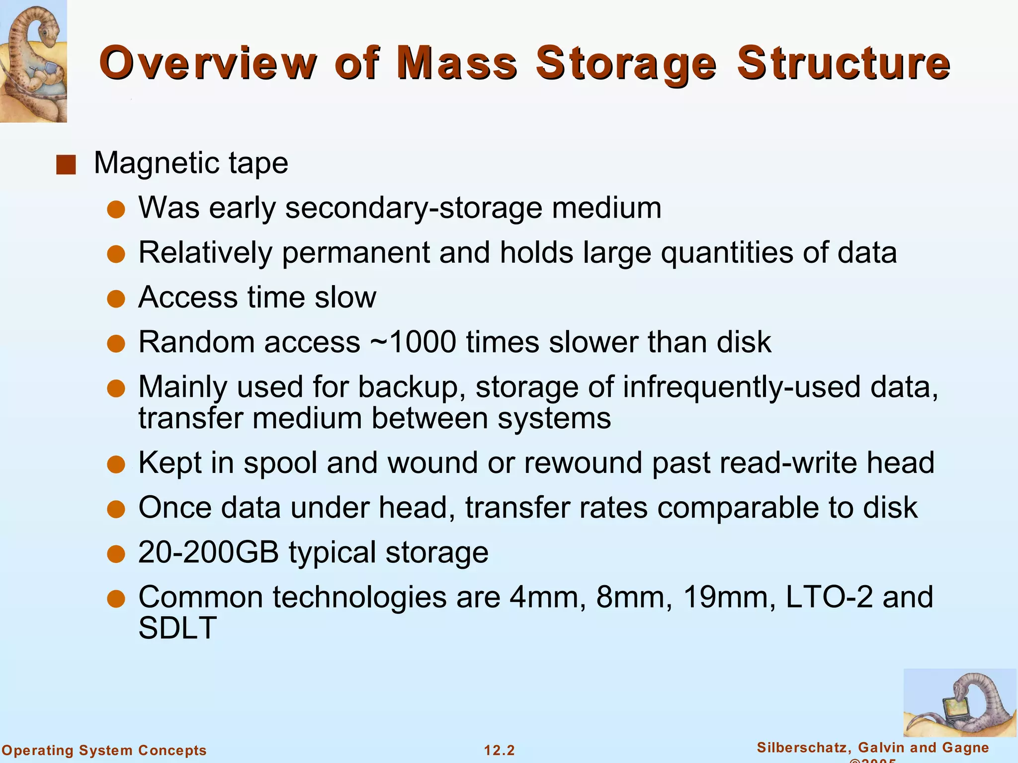
The document discusses secondary storage structures like magnetic tapes and disks. It provides details on:
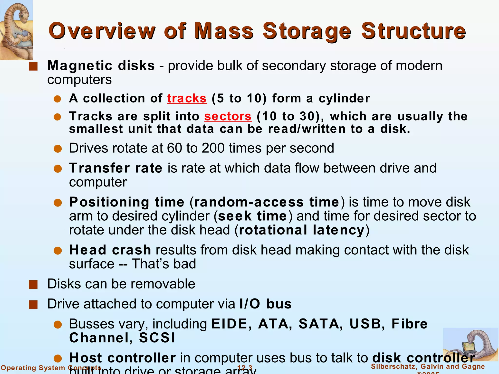
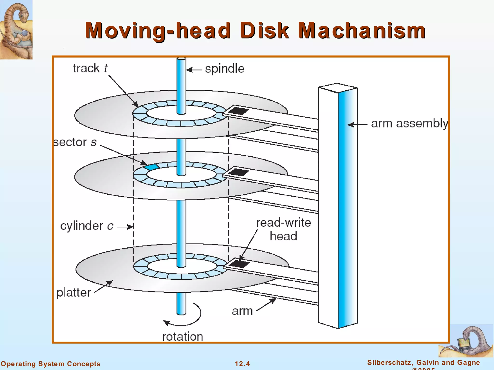
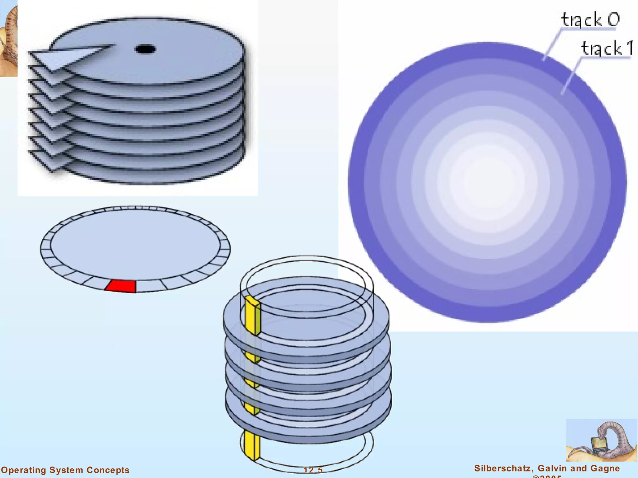
1) Magnetic disks are made up of platters divided into tracks and sectors that store data. Disks use heads to read and write data as the platters rotate.
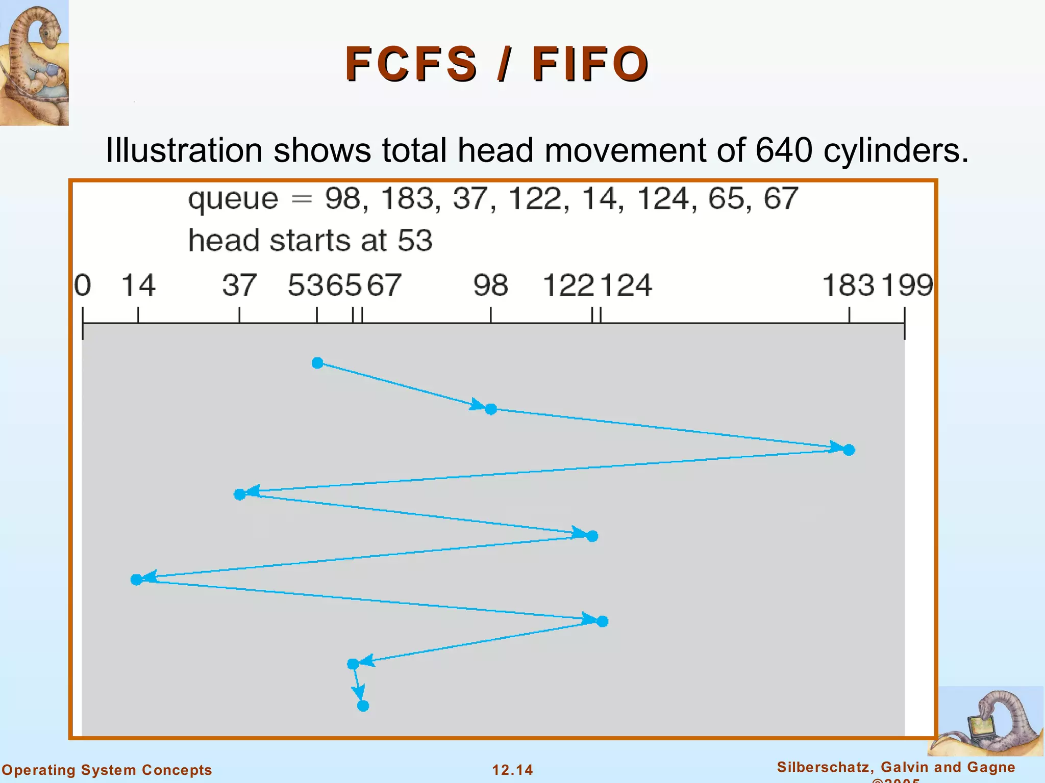
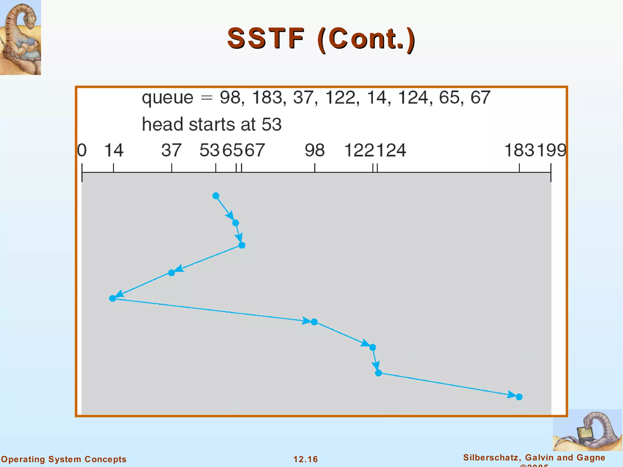
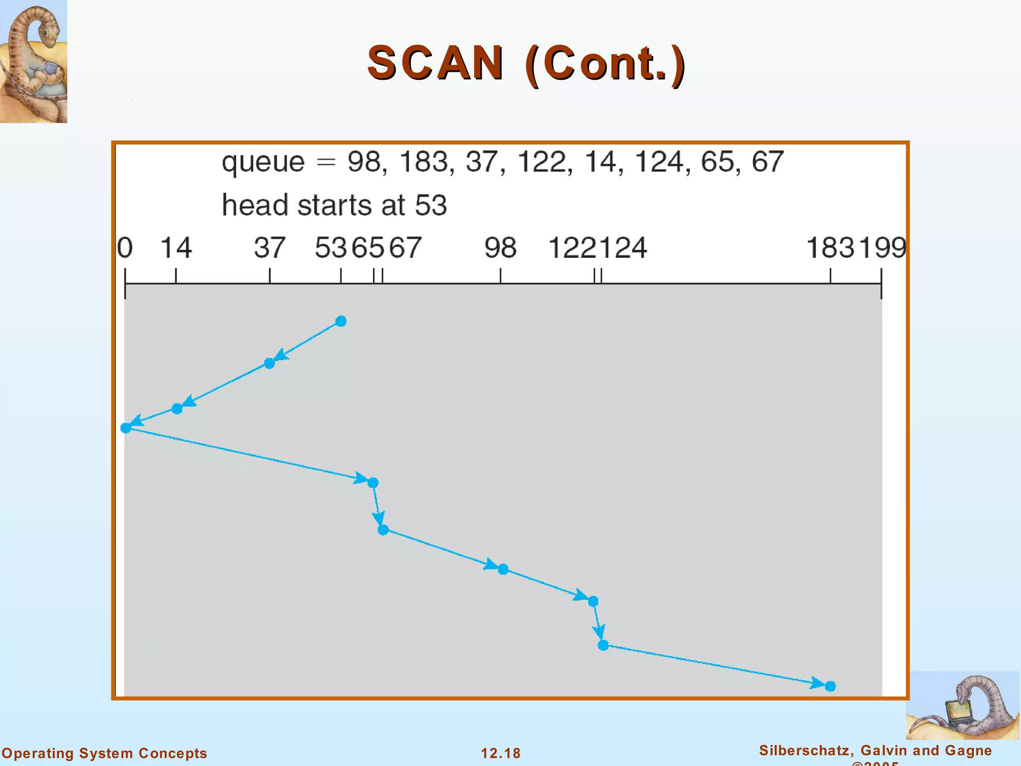
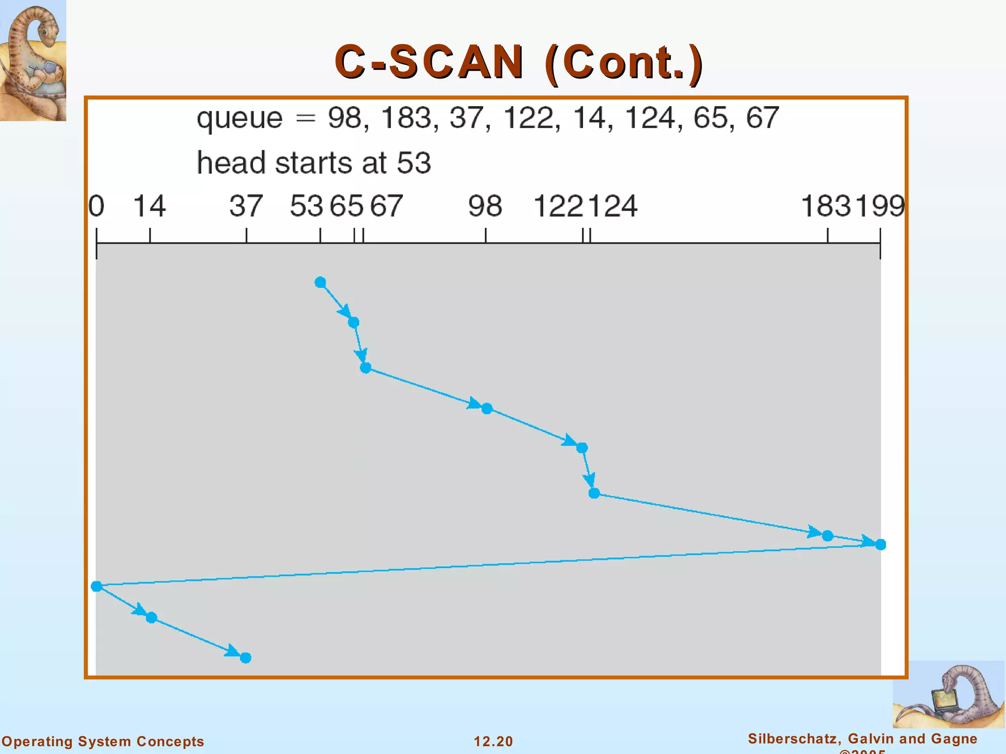
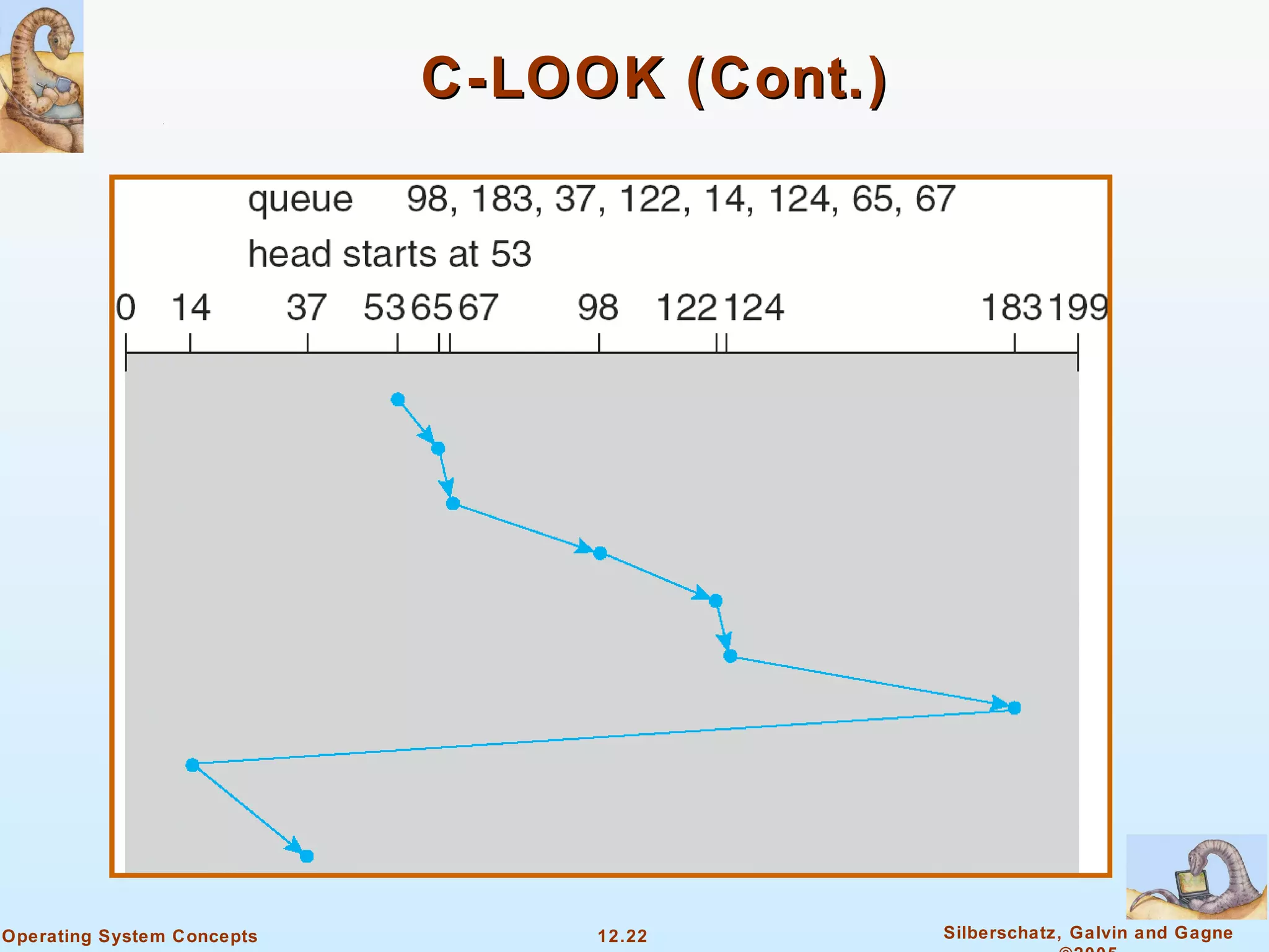
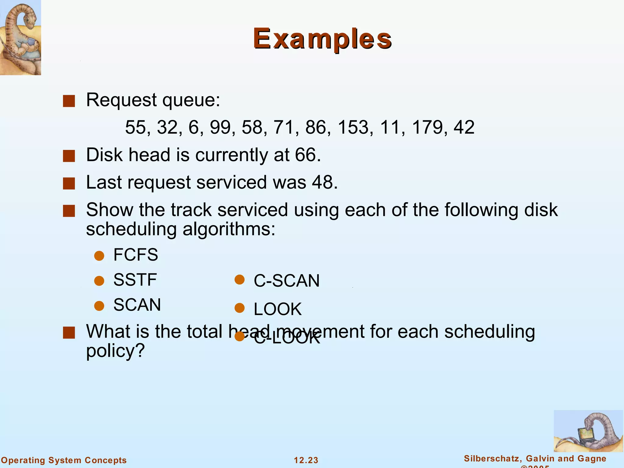
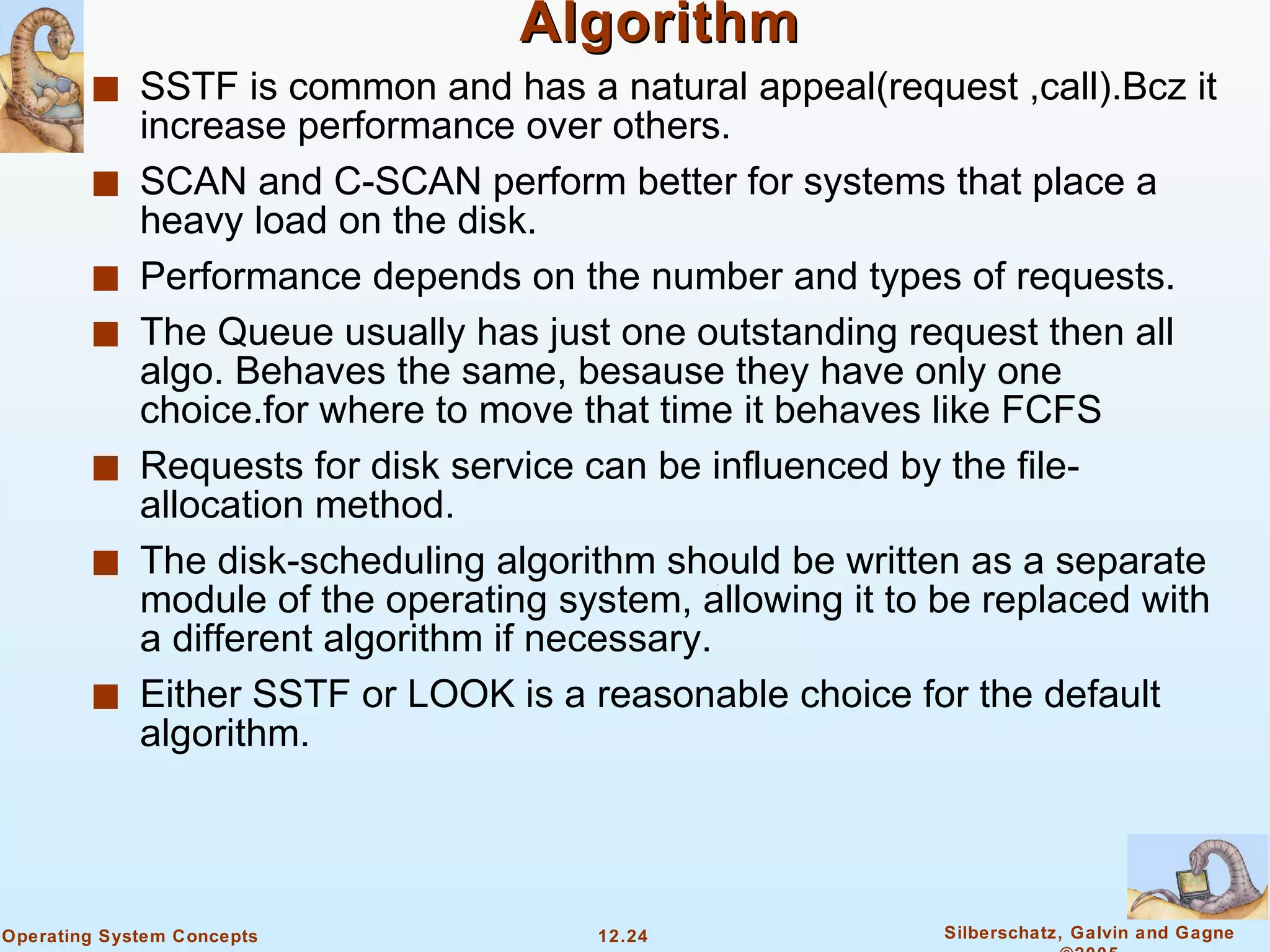
2) Disk scheduling algorithms like SSTF, SCAN, C-SCAN, and C-LOOK are used to determine the order of requests to minimize head movement across cylinders.
3) Formatting prepares disks for use by dividing them into partitions and creating file systems to store operating system and user data structures.