Download to read offline
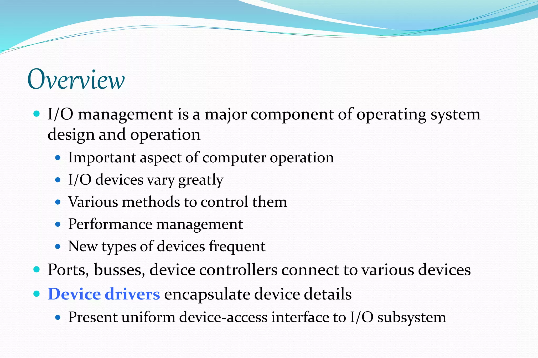
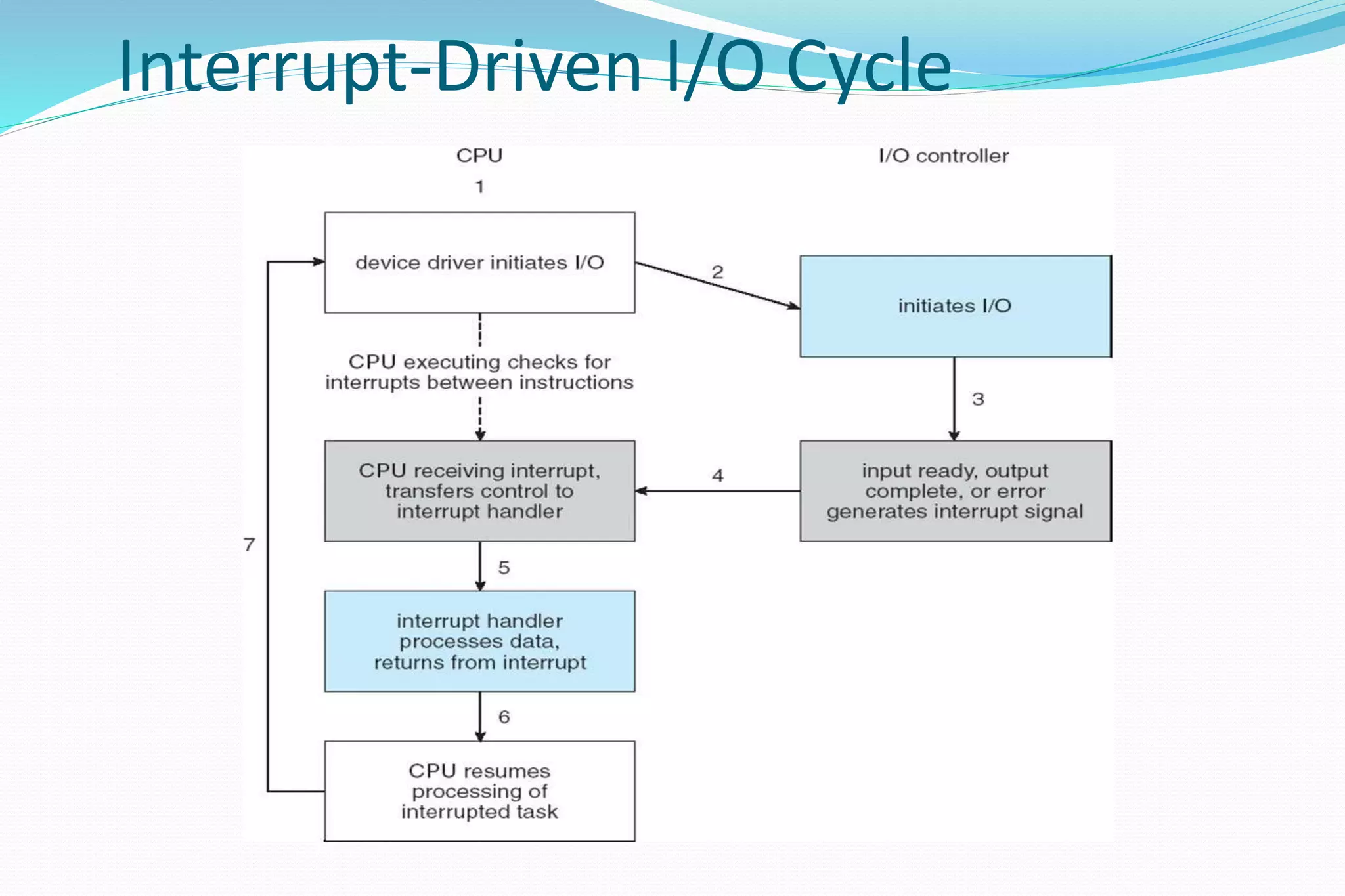
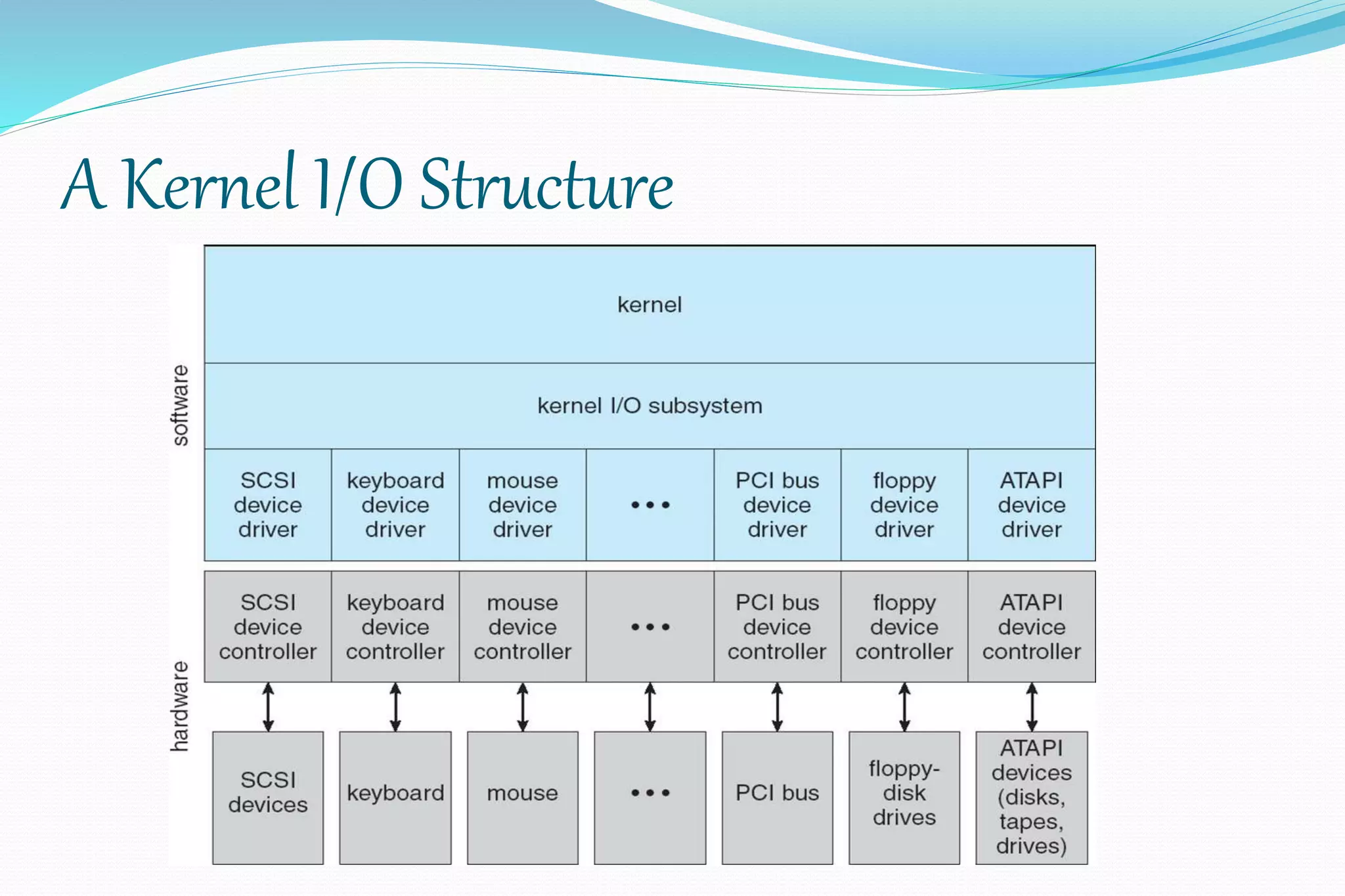
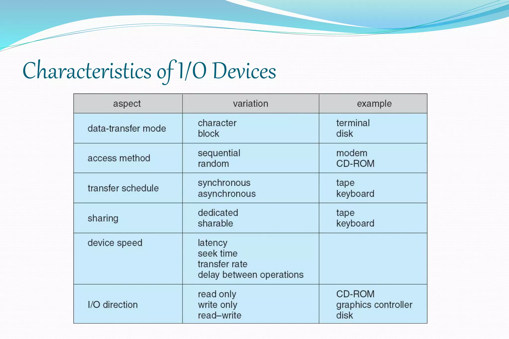
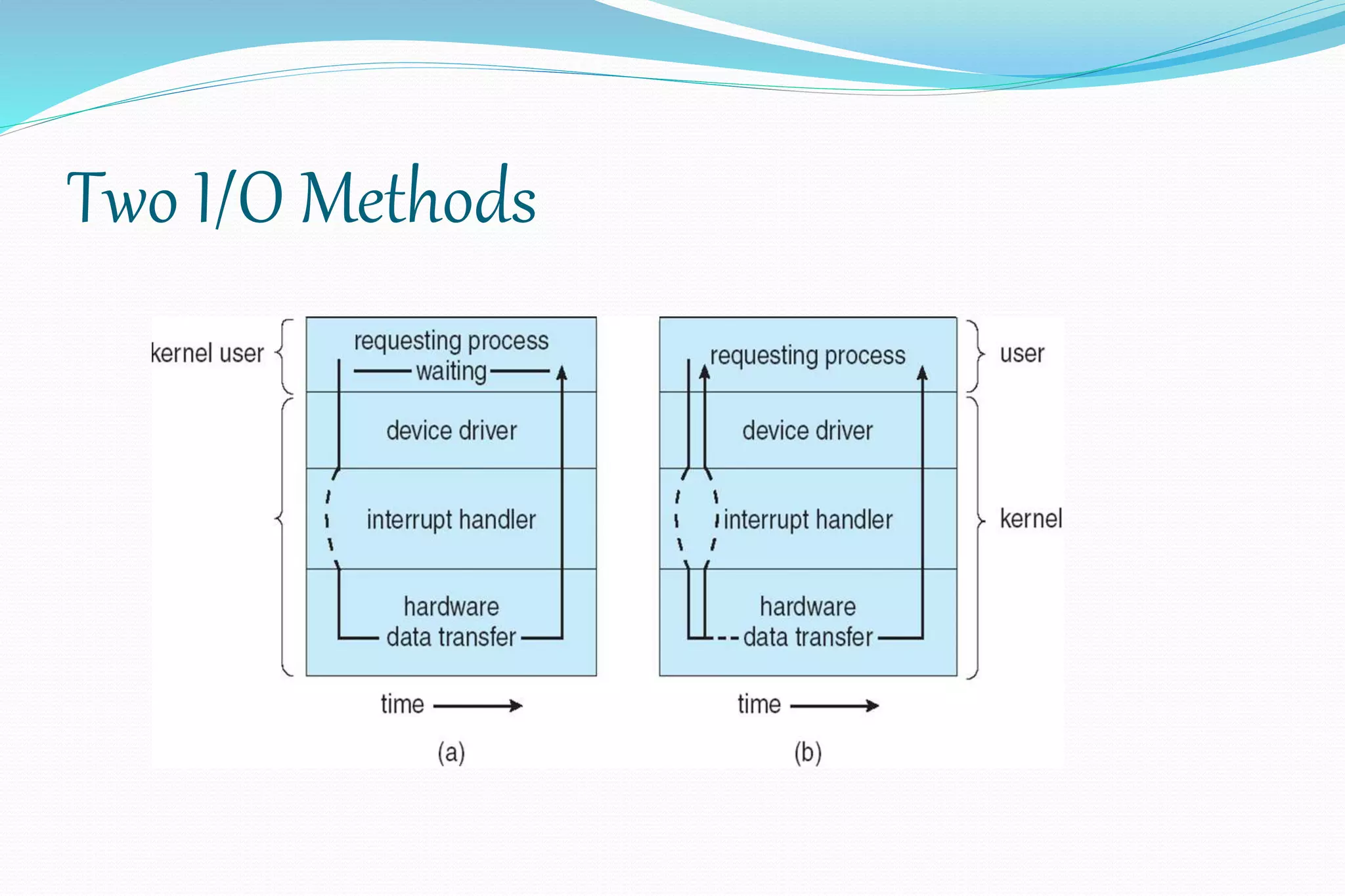
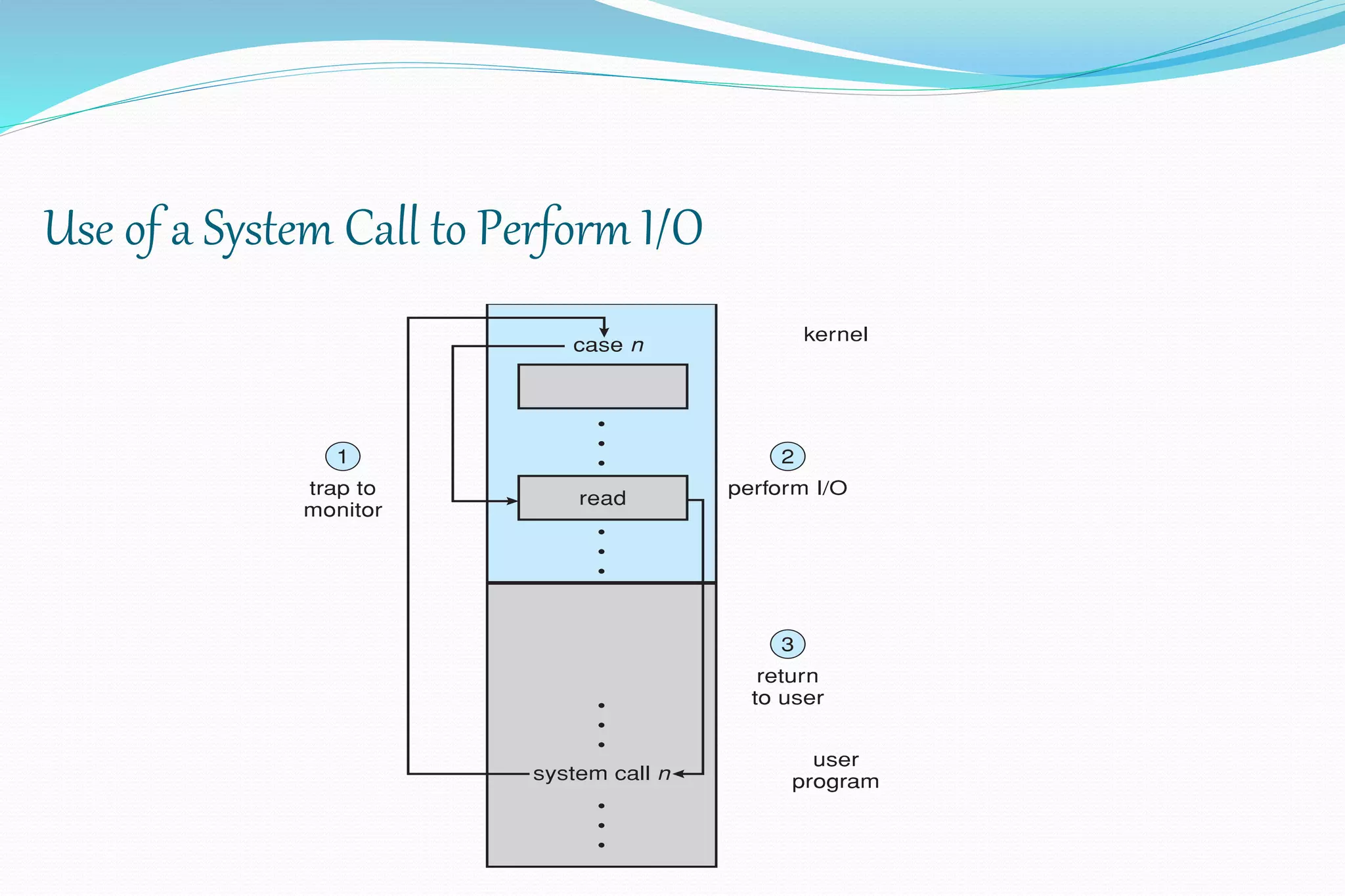

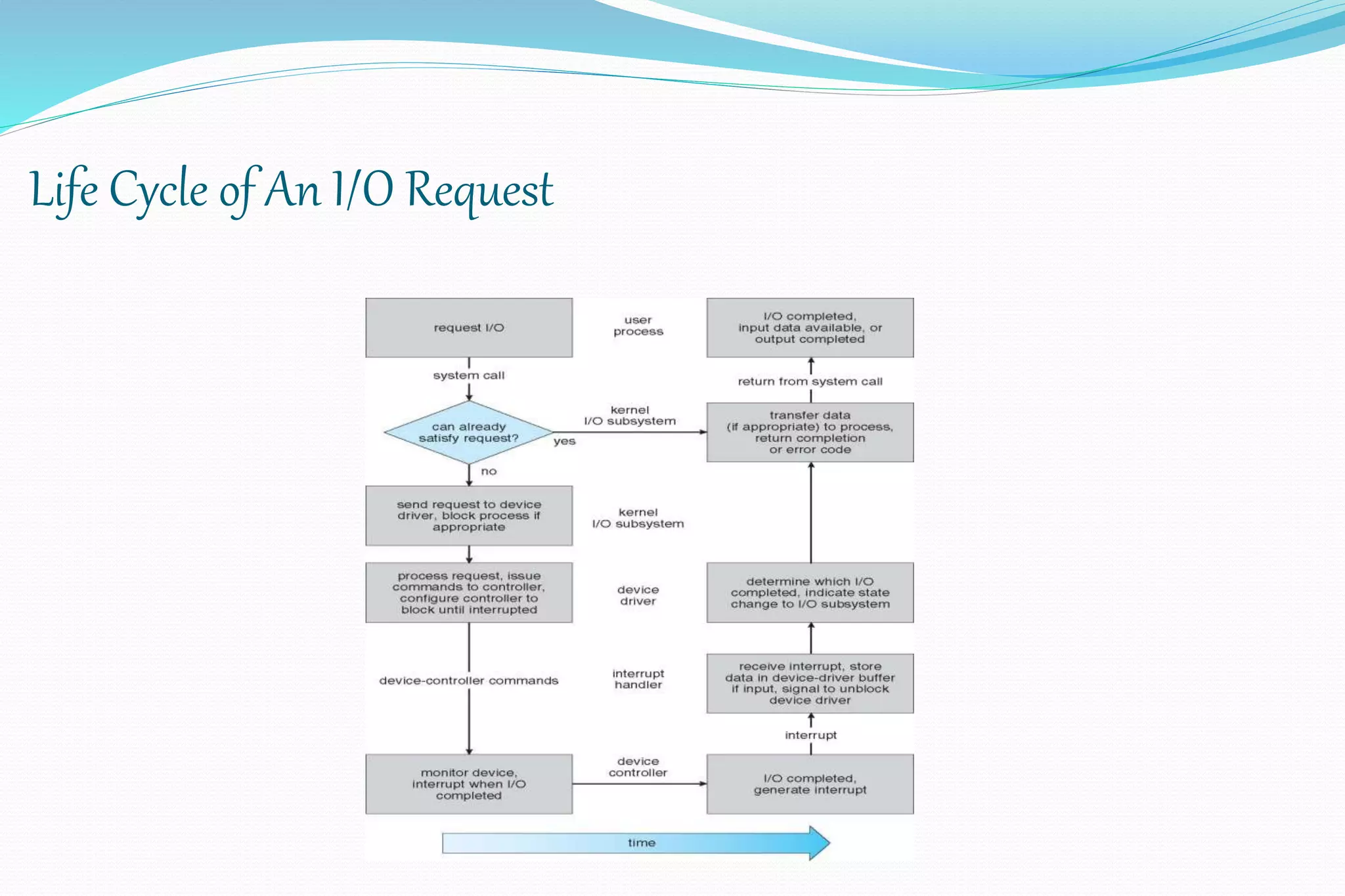
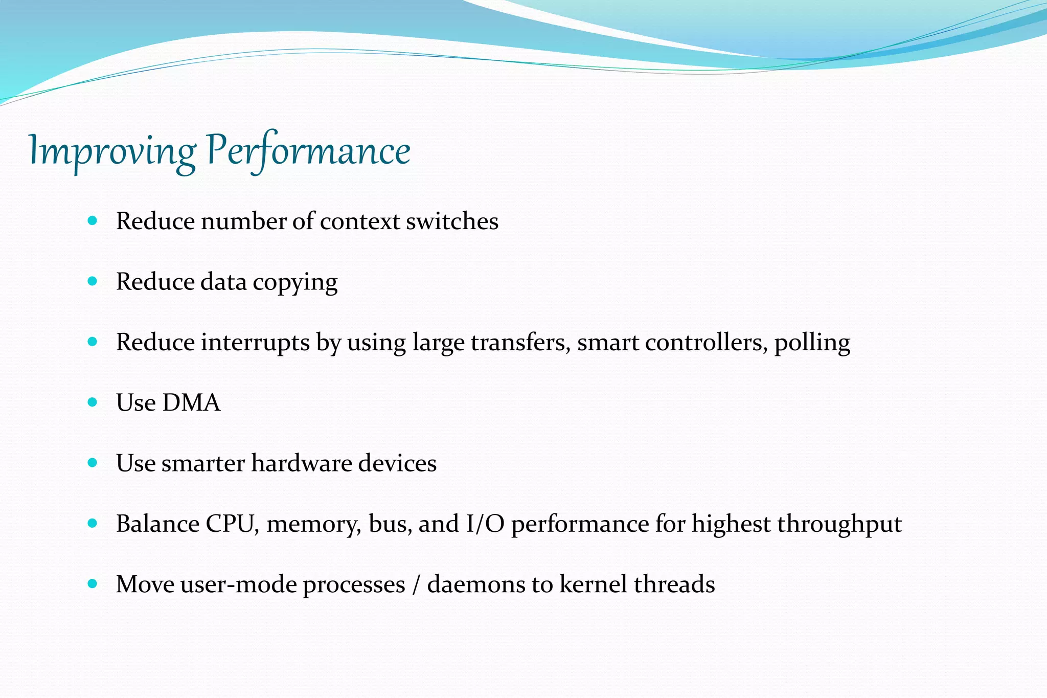
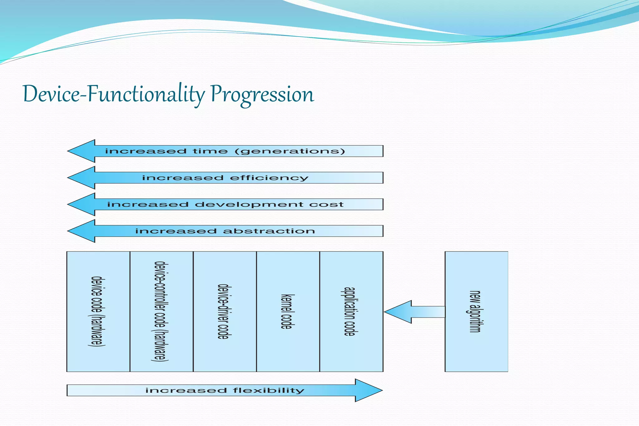


This document discusses I/O systems, including an overview of I/O hardware, the application I/O interface, the kernel I/O subsystem, and I/O performance. It describes how I/O requests are transformed into hardware operations through techniques like interrupts, DMA, polling, and blocking vs. asynchronous I/O. Specific I/O concepts covered include STREAMS, device characteristics, and the life cycle of an I/O request through the kernel.


![Weeks [01 02] 20100921](https://cdn.slidesharecdn.com/ss_thumbnails/weeks01-0220100921-131007221331-phpapp01-thumbnail.jpg?width=640&height=640&fit=bounds)


