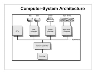
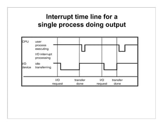
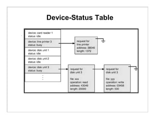
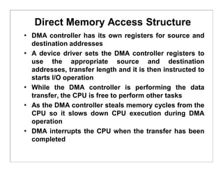
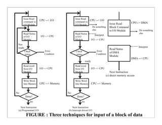
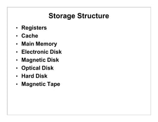
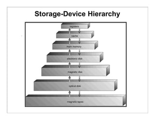
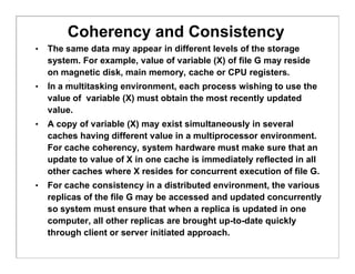
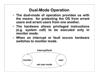
Computer-System Structures
• Computer System Operation
• I/O Structure
• Storage Structure
• Storage Hierarchy
• Hardware Protection
• General System Architecture
Computer-System Operation
• A modern computer system consists of a CPU, memory,
system bus and a number of device controllers
• I/O devices and the CPU can execute concurrently.
• Each device controller is in charge of a particular device
type.
• A device controller for each device which contains local
buffer storage and special purpose registers
• A bootstrap program is required to initialize the
computer system
• CPU moves data from/to main memory to/from local
buffers
• I/O is from the device to local buffer of controller.
• Device controller informs CPU that it has finished its
operation by causing an interrupt.
Computer-System Architecture
Interrupt Handling
• The occurrence of an event is usually signaled by an interrupt from
either the hardware or the software
• System call or monitor call is executed to trigger an interrupt
• When the CPU is interrupted, it stops what it is doing and immediately
transfers execution to a fix location to execute the interrupt service
routine
• On completion of execution of service routine, the CPU resumes the
interrupted computation
• Interrupts are an important part of a modern computer system and
they must be handled quickly
• Interrupt architecture must save the address of the interrupted
instruction.
• Incoming interrupts are disabled while another interrupt is being
processed to prevent a lost interrupt.
• A trap is a software-generated interrupt caused either by an error or a
user request.
• An operating system is interrupt driven.
• In modern systems, priority interrupts have been introduced.
Interrupt Handling
 Each computer design has its own interrupt mechanism
 The interrupt must transfer control to the appropriate interrupt
service routine through a table of pointers which is stored in
LMA
 LMA locations hold the addresses of the interrupt service
routines (interrupt vector) for the various devices
 The operating system preserves the state of the CPU by
storing registers and the program counter.
 Determines which type of interrupt has occurred:
 polling
 vectored interrupt system
 Separate segments of code determine what action should be
taken for each type of interrupt
 The interrupt architecture must also save the address of the
interrupted instruction
 System call is the method used by a process to request action
by the operating system
Interrupt time line for a
single process doing output
I/O Structure
• The computer system has a number of device controllers connected
through a common bus
• A device controller contains local buffer storage and a set of special
purpose registers
• The device driver is responsible for moving the data between the
peripheral devices and it controls its local buffer storage
• I/O interrupts are used by the device controllers for transfer of data
• I/O methods:
 Synchronous
 Asynchronous
• In synchronous method, after I/O starts, control returns to user
program only upon I/O completion.
 Waiting for I/O may be accomplished by either wait instruction or wait
loop
 Wait instruction idles the CPU until the next interrupt
 Wait loop continuous until an interrupt occurs
 At most one I/O request is outstanding at a time, no simultaneous I/O
processing.
I/O Structure
• In asynchronous method, after I/O starts, control returns to
user program without waiting for I/O completion. It requires:-
 System call – request to the operating system to allow user to
wait for I/O completion.
 Device-status table contains entry for each I/O device indicating
its type, address, and state.
 Operating system indexes into I/O device table to determine
device status and to modify table entry to include interrupt.
 OS will also maintain a wait queue for each I/O device.
 An I/O device interrupts when it needs service, OS determines I/O
device and updates its table entry
 An interrupt signals completion of an I/O request, control then
returns from I/O interrupt to another request or user program
 Interrupt schemes vary from system to system
 This method increases system efficiency
Two I/O Methods
Synchronous Asynchronous
Device-Status Table
Direct Memory Access Structure
• Involvement of CPU in data transfer is a time-
consuming process. If the CPU needs two
microseconds to respond to each interrupt and
interrupts arrive every four microseconds then less
time is left for process execution.
• DMA is used for high-speed I/O devices able to
transmit information at close to memory speeds.
• Device controller transfers blocks of data from buffer
storage directly to main memory without CPU
intervention.
• Only one interrupt is generated per block, rather than
the one interrupt per byte.
Direct Memory Access Structure
• DMA controller has its own registers for source and
destination addresses
• A device driver sets the DMA controller registers to
use the appropriate source and destination
addresses, transfer length and it is then instructed to
starts I/O operation
• While the DMA controller is performing the data
transfer, the CPU is free to perform other tasks
• As the DMA controller steals memory cycles from the
CPU so it slows down CPU execution during DMA
operation
• DMA interrupts the CPU when the transfer has been
completed
Check
status
Done?
Issue Read
command to
I/O Module
Read Status
of I/O
Module
Not
ready
Read word
from I/O
Module
Write Word
Into Memory
No
Error
Condition
CPU --> I/O
I/O --> CPU
I/O --> CPU
CPU --> Memory
yes
Next Instruction
(a) Programmed I/O
Check
status
Done?
Issue Read
command to
I/O Module
Read Status
of I/O
Module
ready
Read word
from I/O
Module
Write Word
Into Memory
No
Error
Condition
CPU --> I/O
I/O --> CPU
I/O --> CPU
CPU --> Memory
yes
Next Instruction
(b) Interrupt-driven I/O
Issue Read
Block Command
to I/O Module
Read Status
of DMA
Module
Next Instruction
(c) direct memory access
CPU--> DMA
Do something
else
Interpret
DMA --> CPU
FIGURE : Three techniques for input of a block of data
Do something
else
Interpret
Storage Structure
• Registers
• Cache
• Main Memory
• Electronic Disk
• Magnetic Disk
• Optical Disk
• Hard Disk
• Magnetic Tape
Registers
• Registers are available in the CPU and are
accessible within one cycle of the CPU clock.
• Faster operations are carried out on contents of
CPU registers due to faster accesses.
• Processor does not stall while performing
operations on registers.
• Size of the registers is very small.
• Registers are volatile.
Cache
• CPU needs to stall as RAM is slower than CPU speed for
providing data required to complete the instruction.
• Cache is a faster memory between the CPU and main
memory and is a remedial measure to reduce idling time of
CPU.
• Cache is a memory buffer which stores information required
by the CPU using register-allocation and register-
replacement algorithms.
• Instruction cache holds the next instruction expected to be
executed whereas data cache keeps required data for the
instruction t. They are known as hardware caches.
• Cache have limited size so cache management is a problem
for designers.
• Careful selection of the cache size and of a replacement
algorithm can provide 80 – 99% of all accesses within the
cache – maximizing system performance.
• Caches are volatile.
Main Memory
• Main memory can be viewed as a fast cache for secondary storage.
• Programs must be loaded in the RAM for execution and main memory
is a large storage media that the CPU can access directly.
• Main memory is implemented in a semiconductor technology (DRAM).
• Load and store instructions specify memory addresses for
interaction.
• A typical instruction is executed using fetch-decode-execute cycle.
• All programs and data can not be stored in a RAM because of its
small size and volatility.
• Special I/O instructions allow data transfers between the device
controller registers and main memory.
• In memory-mapped I/O, ranges of memory addresses are set aside
and are mapped to the device registers for providing more convenient
access to I/O devices.
• In programmed I/O, CPU uses polling to watch the bit in the control
register to see whether the device is ready for transfer of data
between device and main memory.
• In an interrupt-driven I/O, CPU receives an interrupt when the device
is ready for the data transfer.
Magnetic Disks
• Magnetic disks provide a large space for storing programs and
data on permanent basis.
• Disks are relatively simple and consist of:
• Platters covered with the magnetic material
• Read-write head
• Disk arm
• Each surface of platter has tracks, sectors and cylinders
• Disk speed depends upon Transfer rate and positioning time (seek
time & rotational latency)
• Head crash damages the magnetic surface and the entire disk is
replaced for safety of data and programs.
• The storage size of a HD is in GBs.
• FDD rotates slowly than HDD which reduces wear on the disk
surface. Its storage capacity is very small compare to HD or CD.
• Buses attached to a disk drive are EIDE, ATA and SCSI.
• Data transfer through a bus is carried out between the host
controller and disk controller.
• Magnetic disks are non-volatile.
Moving-Head Disk Mechanism
Magnetic Tapes
• Magnetic tapes are used to backup the data and
programs in order to protect any loss due to HD failure.
• Magnetic tapes can hold large quantities of data /
programs.
• Access time is too slow compared to HD, CD, Main
Memory etc.
• Magnetic tapes are non-volatile.
• Storage / handling of magnetic tapes requires special
care.
• Recording / reading of information is very slow due to
winding / rewinding of tapes.
• Random access is not available on tapes.
Storage Hierarchy
• Storage systems can be organized in a hierarchy
according to:
 Speed
 Cost
 Capacity
 Volatility
• Registers, cache and memory are constructed using
semiconductor memory and are volatile.
• Electronic disks can be volatile or nonvolatile.
• All secondary storage devices (magnetic disk, optical
disk, floppy disk, magnetic tapes, magnetic drums
etc) are nonvolatile.
Storage-Device Hierarchy
Coherency and Consistency
• The same data may appear in different levels of the storage
system. For example, value of variable (X) of file G may reside
on magnetic disk, main memory, cache or CPU registers.
• In a multitasking environment, each process wishing to use the
value of variable (X) must obtain the most recently updated
value.
• A copy of variable (X) may exist simultaneously in several
caches having different value in a multiprocessor environment.
For cache coherency, system hardware must make sure that an
update to value of X in one cache is immediately reflected in all
other caches where X resides for concurrent execution of file G.
• For cache consistency in a distributed environment, the various
replicas of the file G may be accessed and updated concurrently
so system must ensure that when a replica is updated in one
computer, all other replicas are brought up-to-date quickly
through client or server initiated approach.
Migration of X From Disk to Register
X X X
Hardware Protection
 Dual-Mode Operation
 I/O Protection
 Memory Protection
 CPU Protection
DUAL MODE OPERATION
• Sharing of system resources improved CPU utilization
but increased problems. Many jobs could be affected by
a bug in one program.
• A good OS must ensure that a faulty program cannot
cause other programs to execute incorrectly.
• If a user program fails, the hardware will trap to OS, the
OS dumps the memory of the program for debugging and
terminates it.
• The hardware-supported dual-mode operation protects
the OS, all other programs and their data from any
malfunctioning program.
 User-mode of operation (mode-bit is 1).
 Monitor/supervisor/system mode of operation (mode-bit is 0).
• Whenever an interrupt or trap occurs, the hardware
switches from user-mode to monitor-mode. OS is in the
monitor-mode.
Dual-Mode Operation
• The dual-mode of operation provides us with
the means for protecting the OS from errant
users and errant users from one another.
• The hardware allows privileged instructions
(e.g. system call) to be executed only in
monitor mode.
• When an interrupt or fault occurs hardware
switches to monitor mode.
monitor user
Interrupt/fault
set user mode
I/O Protection
 All I/O instructions are defined as privileged
instructions so users cannot issue I/O instructions
from user mode.
 Must ensure that a user program could never gain
control of the computer in monitor mode (i.e., a user
program that, as part of its execution, stores a new
address in the interrupt vector).
 To do I/O, a user programme executes a system call to
request that the OS perform I/O on its behalf and
returns the control to the users after completion of I/O
operation.
Use of a System Call to Perform I/O
Memory Protection
 Must provide memory protection for the interrupt
vector, the interrupt service routines and user
programs from one another.
 In order to have memory protection, two registers are
used to determine the range of legal addresses a
program may access:
 Base register – holds the smallest legal physical memory
address.
 Limit register – contains the size of the range
 Memory outside the defined range is protected.
 A trap is generated if any user’s program attempts to
access unauthorized memory area.
 When executing in monitor mode, the operating
system has unrestricted access to both monitor and
user’s memory.
 The load instructions for the base and limit registers
are privileged instructions.
Use of a Base and Limit Register
Hardware Address Protection
CPU Protection
 A user program may:
be stuck in an infinite loop
fail to call system services
fail to return control to the OS
 Timer – interrupts computer after specified period to
ensure operating system maintains control.
Timer is decremented every clock tick.
When timer reaches the value 0, an interrupt occurs and
control is automatically transferred to the OS.
 Timer is also commonly used to implement time
sharing mechanism.
 Time can be used to compute the current time.
 Load-timer is a privileged instruction.
Network Structure
 Local Area Networks (LAN)
LANs were introduced in 1970 for economical use of a
number of small computers and sharing of computer
resources.
LANs cover a small geographical area and are
generally used in an office environment.
Communication links of LANs have a higher speed
and lower error rate.
High-quality cables (TP, Fiber Optic etc) are used for
establishment of LANs.
Common topologies are bus, ring and star.
Communications speed range from Mbps to Gbps.
A typical LAN may consist of PCs/Laptops/PDAs,
shared peripheral devices and one or more gateways.
Local Area Network Structure
Network Structure
 Wide Area Networks (WAN)
 WANs emerged in the late 1960s to provide efficient communication among sites.
 WANs are physically distributed over a large geographical area.
 Hardware and software resources are shared conveniently and economically by a wide
community of users.
 ARPANet grew from four sites to millions of sites using internet.
 The communication links (telephone lines, leased lines, microwave links, satellite
channels etc) are relatively slow and less reliable.
 Communication processors control the communication links for transferring information
among the various sites.
 The internet WAN provide the ability for hosts at geographically separated sites to
communicate with one another.
 The host computers differ from each other in type, speed, word length, operating system
etc.
 Connections between networks use a telephone-system service to provide
communication:
 T1 service provides a transfer rate of 1.544 Mbps
 T2 service provides a transfer rate of 6.312 Mbps
 T3 service provides a transfer rate of 44.736 Mbps
 T4 service provides a transfer rate of 274.176 Mbps
Wide Area Network Structure
The router control the path each message takes through the net. Dynamic routing
enhances communication efficiency whereas static routing reduces security risks.
Modems convert digital data to analog signals and vice versa for communication.
WANs are slower than LANs (1200 bps to 1 Mbps) and uses PPP for connecting
computers to the internet.

computer system structure

  • 1.
    Computer-System Structures • ComputerSystem Operation • I/O Structure • Storage Structure • Storage Hierarchy • Hardware Protection • General System Architecture
  • 2.
    Computer-System Operation • Amodern computer system consists of a CPU, memory, system bus and a number of device controllers • I/O devices and the CPU can execute concurrently. • Each device controller is in charge of a particular device type. • A device controller for each device which contains local buffer storage and special purpose registers • A bootstrap program is required to initialize the computer system • CPU moves data from/to main memory to/from local buffers • I/O is from the device to local buffer of controller. • Device controller informs CPU that it has finished its operation by causing an interrupt.
  • 3.
  • 4.
    Interrupt Handling • Theoccurrence of an event is usually signaled by an interrupt from either the hardware or the software • System call or monitor call is executed to trigger an interrupt • When the CPU is interrupted, it stops what it is doing and immediately transfers execution to a fix location to execute the interrupt service routine • On completion of execution of service routine, the CPU resumes the interrupted computation • Interrupts are an important part of a modern computer system and they must be handled quickly • Interrupt architecture must save the address of the interrupted instruction. • Incoming interrupts are disabled while another interrupt is being processed to prevent a lost interrupt. • A trap is a software-generated interrupt caused either by an error or a user request. • An operating system is interrupt driven. • In modern systems, priority interrupts have been introduced.
  • 5.
    Interrupt Handling  Eachcomputer design has its own interrupt mechanism  The interrupt must transfer control to the appropriate interrupt service routine through a table of pointers which is stored in LMA  LMA locations hold the addresses of the interrupt service routines (interrupt vector) for the various devices  The operating system preserves the state of the CPU by storing registers and the program counter.  Determines which type of interrupt has occurred:  polling  vectored interrupt system  Separate segments of code determine what action should be taken for each type of interrupt  The interrupt architecture must also save the address of the interrupted instruction  System call is the method used by a process to request action by the operating system
  • 6.
    Interrupt time linefor a single process doing output
  • 7.
    I/O Structure • Thecomputer system has a number of device controllers connected through a common bus • A device controller contains local buffer storage and a set of special purpose registers • The device driver is responsible for moving the data between the peripheral devices and it controls its local buffer storage • I/O interrupts are used by the device controllers for transfer of data • I/O methods:  Synchronous  Asynchronous • In synchronous method, after I/O starts, control returns to user program only upon I/O completion.  Waiting for I/O may be accomplished by either wait instruction or wait loop  Wait instruction idles the CPU until the next interrupt  Wait loop continuous until an interrupt occurs  At most one I/O request is outstanding at a time, no simultaneous I/O processing.
  • 8.
    I/O Structure • Inasynchronous method, after I/O starts, control returns to user program without waiting for I/O completion. It requires:-  System call – request to the operating system to allow user to wait for I/O completion.  Device-status table contains entry for each I/O device indicating its type, address, and state.  Operating system indexes into I/O device table to determine device status and to modify table entry to include interrupt.  OS will also maintain a wait queue for each I/O device.  An I/O device interrupts when it needs service, OS determines I/O device and updates its table entry  An interrupt signals completion of an I/O request, control then returns from I/O interrupt to another request or user program  Interrupt schemes vary from system to system  This method increases system efficiency
  • 9.
  • 10.
  • 11.
    Direct Memory AccessStructure • Involvement of CPU in data transfer is a time- consuming process. If the CPU needs two microseconds to respond to each interrupt and interrupts arrive every four microseconds then less time is left for process execution. • DMA is used for high-speed I/O devices able to transmit information at close to memory speeds. • Device controller transfers blocks of data from buffer storage directly to main memory without CPU intervention. • Only one interrupt is generated per block, rather than the one interrupt per byte.
  • 12.
    Direct Memory AccessStructure • DMA controller has its own registers for source and destination addresses • A device driver sets the DMA controller registers to use the appropriate source and destination addresses, transfer length and it is then instructed to starts I/O operation • While the DMA controller is performing the data transfer, the CPU is free to perform other tasks • As the DMA controller steals memory cycles from the CPU so it slows down CPU execution during DMA operation • DMA interrupts the CPU when the transfer has been completed
  • 13.
    Check status Done? Issue Read command to I/OModule Read Status of I/O Module Not ready Read word from I/O Module Write Word Into Memory No Error Condition CPU --> I/O I/O --> CPU I/O --> CPU CPU --> Memory yes Next Instruction (a) Programmed I/O Check status Done? Issue Read command to I/O Module Read Status of I/O Module ready Read word from I/O Module Write Word Into Memory No Error Condition CPU --> I/O I/O --> CPU I/O --> CPU CPU --> Memory yes Next Instruction (b) Interrupt-driven I/O Issue Read Block Command to I/O Module Read Status of DMA Module Next Instruction (c) direct memory access CPU--> DMA Do something else Interpret DMA --> CPU FIGURE : Three techniques for input of a block of data Do something else Interpret
  • 14.
    Storage Structure • Registers •Cache • Main Memory • Electronic Disk • Magnetic Disk • Optical Disk • Hard Disk • Magnetic Tape
  • 15.
    Registers • Registers areavailable in the CPU and are accessible within one cycle of the CPU clock. • Faster operations are carried out on contents of CPU registers due to faster accesses. • Processor does not stall while performing operations on registers. • Size of the registers is very small. • Registers are volatile.
  • 16.
    Cache • CPU needsto stall as RAM is slower than CPU speed for providing data required to complete the instruction. • Cache is a faster memory between the CPU and main memory and is a remedial measure to reduce idling time of CPU. • Cache is a memory buffer which stores information required by the CPU using register-allocation and register- replacement algorithms. • Instruction cache holds the next instruction expected to be executed whereas data cache keeps required data for the instruction t. They are known as hardware caches. • Cache have limited size so cache management is a problem for designers. • Careful selection of the cache size and of a replacement algorithm can provide 80 – 99% of all accesses within the cache – maximizing system performance. • Caches are volatile.
  • 17.
    Main Memory • Mainmemory can be viewed as a fast cache for secondary storage. • Programs must be loaded in the RAM for execution and main memory is a large storage media that the CPU can access directly. • Main memory is implemented in a semiconductor technology (DRAM). • Load and store instructions specify memory addresses for interaction. • A typical instruction is executed using fetch-decode-execute cycle. • All programs and data can not be stored in a RAM because of its small size and volatility. • Special I/O instructions allow data transfers between the device controller registers and main memory. • In memory-mapped I/O, ranges of memory addresses are set aside and are mapped to the device registers for providing more convenient access to I/O devices. • In programmed I/O, CPU uses polling to watch the bit in the control register to see whether the device is ready for transfer of data between device and main memory. • In an interrupt-driven I/O, CPU receives an interrupt when the device is ready for the data transfer.
  • 18.
    Magnetic Disks • Magneticdisks provide a large space for storing programs and data on permanent basis. • Disks are relatively simple and consist of: • Platters covered with the magnetic material • Read-write head • Disk arm • Each surface of platter has tracks, sectors and cylinders • Disk speed depends upon Transfer rate and positioning time (seek time & rotational latency) • Head crash damages the magnetic surface and the entire disk is replaced for safety of data and programs. • The storage size of a HD is in GBs. • FDD rotates slowly than HDD which reduces wear on the disk surface. Its storage capacity is very small compare to HD or CD. • Buses attached to a disk drive are EIDE, ATA and SCSI. • Data transfer through a bus is carried out between the host controller and disk controller. • Magnetic disks are non-volatile.
  • 19.
  • 20.
    Magnetic Tapes • Magnetictapes are used to backup the data and programs in order to protect any loss due to HD failure. • Magnetic tapes can hold large quantities of data / programs. • Access time is too slow compared to HD, CD, Main Memory etc. • Magnetic tapes are non-volatile. • Storage / handling of magnetic tapes requires special care. • Recording / reading of information is very slow due to winding / rewinding of tapes. • Random access is not available on tapes.
  • 21.
    Storage Hierarchy • Storagesystems can be organized in a hierarchy according to:  Speed  Cost  Capacity  Volatility • Registers, cache and memory are constructed using semiconductor memory and are volatile. • Electronic disks can be volatile or nonvolatile. • All secondary storage devices (magnetic disk, optical disk, floppy disk, magnetic tapes, magnetic drums etc) are nonvolatile.
  • 22.
  • 23.
    Coherency and Consistency •The same data may appear in different levels of the storage system. For example, value of variable (X) of file G may reside on magnetic disk, main memory, cache or CPU registers. • In a multitasking environment, each process wishing to use the value of variable (X) must obtain the most recently updated value. • A copy of variable (X) may exist simultaneously in several caches having different value in a multiprocessor environment. For cache coherency, system hardware must make sure that an update to value of X in one cache is immediately reflected in all other caches where X resides for concurrent execution of file G. • For cache consistency in a distributed environment, the various replicas of the file G may be accessed and updated concurrently so system must ensure that when a replica is updated in one computer, all other replicas are brought up-to-date quickly through client or server initiated approach.
  • 24.
    Migration of XFrom Disk to Register X X X
  • 25.
    Hardware Protection  Dual-ModeOperation  I/O Protection  Memory Protection  CPU Protection
  • 26.
    DUAL MODE OPERATION •Sharing of system resources improved CPU utilization but increased problems. Many jobs could be affected by a bug in one program. • A good OS must ensure that a faulty program cannot cause other programs to execute incorrectly. • If a user program fails, the hardware will trap to OS, the OS dumps the memory of the program for debugging and terminates it. • The hardware-supported dual-mode operation protects the OS, all other programs and their data from any malfunctioning program.  User-mode of operation (mode-bit is 1).  Monitor/supervisor/system mode of operation (mode-bit is 0). • Whenever an interrupt or trap occurs, the hardware switches from user-mode to monitor-mode. OS is in the monitor-mode.
  • 27.
    Dual-Mode Operation • Thedual-mode of operation provides us with the means for protecting the OS from errant users and errant users from one another. • The hardware allows privileged instructions (e.g. system call) to be executed only in monitor mode. • When an interrupt or fault occurs hardware switches to monitor mode. monitor user Interrupt/fault set user mode
  • 28.
    I/O Protection  AllI/O instructions are defined as privileged instructions so users cannot issue I/O instructions from user mode.  Must ensure that a user program could never gain control of the computer in monitor mode (i.e., a user program that, as part of its execution, stores a new address in the interrupt vector).  To do I/O, a user programme executes a system call to request that the OS perform I/O on its behalf and returns the control to the users after completion of I/O operation.
  • 29.
    Use of aSystem Call to Perform I/O
  • 30.
    Memory Protection  Mustprovide memory protection for the interrupt vector, the interrupt service routines and user programs from one another.  In order to have memory protection, two registers are used to determine the range of legal addresses a program may access:  Base register – holds the smallest legal physical memory address.  Limit register – contains the size of the range  Memory outside the defined range is protected.  A trap is generated if any user’s program attempts to access unauthorized memory area.  When executing in monitor mode, the operating system has unrestricted access to both monitor and user’s memory.  The load instructions for the base and limit registers are privileged instructions.
  • 31.
    Use of aBase and Limit Register
  • 32.
  • 33.
    CPU Protection  Auser program may: be stuck in an infinite loop fail to call system services fail to return control to the OS  Timer – interrupts computer after specified period to ensure operating system maintains control. Timer is decremented every clock tick. When timer reaches the value 0, an interrupt occurs and control is automatically transferred to the OS.  Timer is also commonly used to implement time sharing mechanism.  Time can be used to compute the current time.  Load-timer is a privileged instruction.
  • 34.
    Network Structure  LocalArea Networks (LAN) LANs were introduced in 1970 for economical use of a number of small computers and sharing of computer resources. LANs cover a small geographical area and are generally used in an office environment. Communication links of LANs have a higher speed and lower error rate. High-quality cables (TP, Fiber Optic etc) are used for establishment of LANs. Common topologies are bus, ring and star. Communications speed range from Mbps to Gbps. A typical LAN may consist of PCs/Laptops/PDAs, shared peripheral devices and one or more gateways.
  • 35.
  • 36.
    Network Structure  WideArea Networks (WAN)  WANs emerged in the late 1960s to provide efficient communication among sites.  WANs are physically distributed over a large geographical area.  Hardware and software resources are shared conveniently and economically by a wide community of users.  ARPANet grew from four sites to millions of sites using internet.  The communication links (telephone lines, leased lines, microwave links, satellite channels etc) are relatively slow and less reliable.  Communication processors control the communication links for transferring information among the various sites.  The internet WAN provide the ability for hosts at geographically separated sites to communicate with one another.  The host computers differ from each other in type, speed, word length, operating system etc.  Connections between networks use a telephone-system service to provide communication:  T1 service provides a transfer rate of 1.544 Mbps  T2 service provides a transfer rate of 6.312 Mbps  T3 service provides a transfer rate of 44.736 Mbps  T4 service provides a transfer rate of 274.176 Mbps
  • 37.
    Wide Area NetworkStructure The router control the path each message takes through the net. Dynamic routing enhances communication efficiency whereas static routing reduces security risks. Modems convert digital data to analog signals and vice versa for communication. WANs are slower than LANs (1200 bps to 1 Mbps) and uses PPP for connecting computers to the internet.