Downloaded 231 times
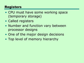
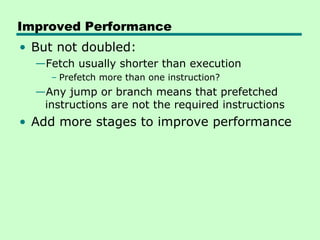
![CPSR
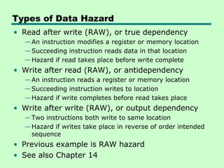
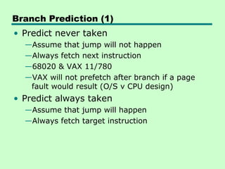
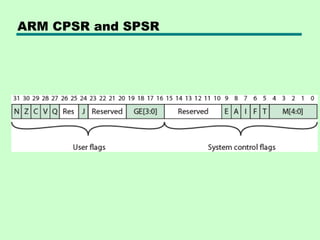
• CPSR process status register
—Exception modes have dedicated SPSR
• 16 msb are user flags
—Condition codes (N,Z,C,V)
—Q – overflow or saturation in some SMID
instructions
—J – Jazelle (8 bit) instructions
—GEE[3:0] SMID use [19:16] as greater than or
equal flag
• 16 lsb system flags for privilege modes
—E – endian
—Interrupt disable
—T – Normal or Thumb instruction
—Mode](https://image.slidesharecdn.com/12processorstructureandfunction-130103104829-phpapp02/85/12-processor-structure-and-function-71-320.jpg)

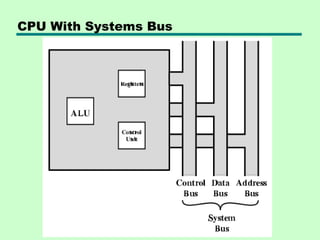
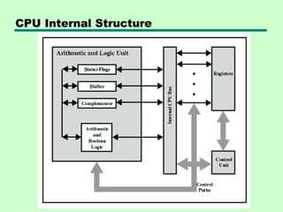
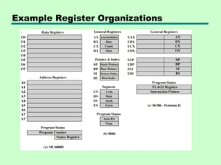
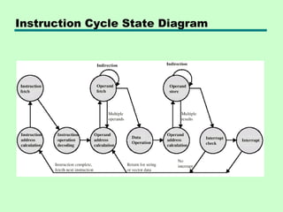
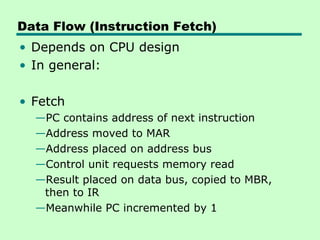
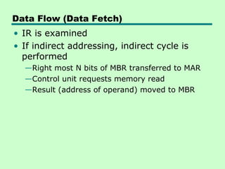
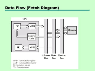
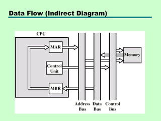
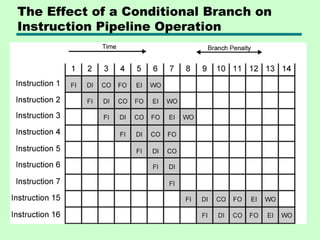
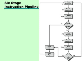
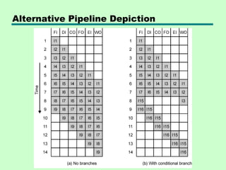
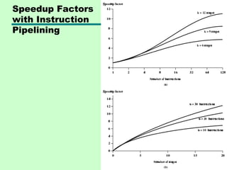
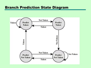
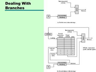
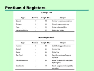
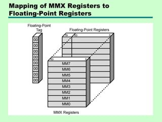
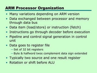
This chapter discusses processor structure and function. It covers the basic components of a CPU including registers, instruction cycles, and data flow. Key points include: - A CPU must fetch, interpret, fetch operands for, process, and write data from instructions. It uses registers for temporary storage and a program counter to keep track of instructions. - Common registers include general purpose, data, address, condition code, control/status, and program status registers. General purpose registers can vary in number, size, and whether they are general or specialized use. - An instruction cycle involves fetching an instruction from memory, decoding it, fetching operands, executing the instruction, and writing results. Pipelining and branch prediction are