The document provides an introduction to fiber optics and discusses several key topics:
1. It describes the basic components and operation of an optical fiber system including the transmitter, fiber cable, and receiver. Light pulses are transmitted through the fiber and detected at the receiving end.
2. The evolution of fiber optic systems is summarized from first to fifth generations with increasing bit rates and transmission distances over time.
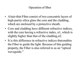
3. The basic structure and properties of optical fibers are outlined, including the core, cladding, buffer, and jacket layers. Total internal reflection within the core allows light to propagate along the fiber.
4. Two main fiber types - step index and graded index - are introduced based on differences in their refractive