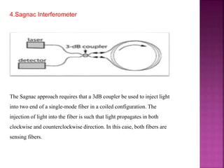
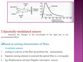
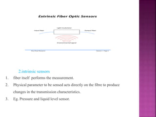
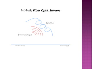
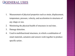
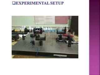
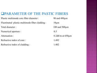
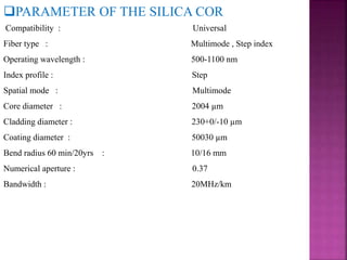
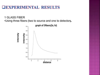
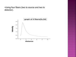
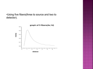
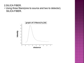
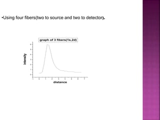
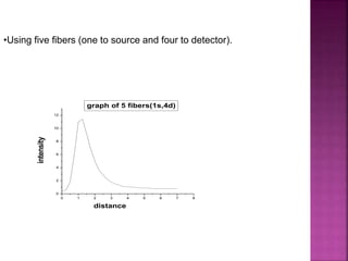
PRESENTED BY
VARSHA.C.PALAVE
1. INTRODUCTION OF OPTICAL FIBER
Principles involved
Types of fiber
Advantages
disadvantages
2. INTRODUCTION OF SENSORS
Sensors
Optical fiber sensors
Procedure involved in sensors
Classifications
General uses
Advantages
3. DISPLACEMENT SENSOR
Principles involved
Experimental set up
Experimental results
Applications
4. CONCLUSION
In 1952 physicist Narinder Singh Kapany ,based on studies conducted by english
physicist John Tyndall that light could travel in curve inside a material (in Tyndall
experiments this material was water ), could conclude his experiments that led to the
invention of the optical fiber. Optical fiber is an excellent transmition medium used
by systems that requires high bandwidth, like the telephony systems ,video
conference, local network(LANs), etc
There two main advantages on optical fibers over metallic cables. Optical fiber is
totally imune to electromagnetic interference, which means that data isn’t corrupted
during their transmition. The second main advantage is that optical fiber doesn’t
conduct electrical current, thus no electricity related issue is found by using optical
fibers, like electrical potential difference between devices or problems with
lightnings.
An optical fiber is a flexible,
transparent fiber made of high quality
extruded glass (silica) or plastic,
slightly thicker than a human hair. It
can function as a waveguide, or “light
pipe”, to transmit light between the
two ends of the fiberFigure 1 A bundle of optical
fibers
SNELL’S LAW:
n1 sin J = n2 sin J
where n is refractive
index
 Guidance is achieved through multiple
reflections at the fiber walls.
 Core, transparent dielectric material,
surrounded by another dielectric material with a
lower refractive index called cladding. (n1 >n2)
 In practice, there is a third protective layer
called jacket.
Figure 2 typical structure of optical fiber
n1
n2
J1
J2
glass
Mirror reflects light
Transparent medium refracts light
mirror
TOTAL INTERNAL
REFLECTION OF
LIGHT
N
INCIDENT RAY
REFRACTED RAY
The ray is refracted parallel to
the edge of the block at the
Critical angle
Occur when light inside a glass block hits the edge at certain angles
Remember – if light hits the boundary between two media it will pass straight
through
As you increase the angle of incidence, the ray gets bent
However – at a particular angle called the Critical Angle, something strange
happens
a single-mode optical fiber (SMF) is an optical fiber designed to carry only a single
ray of light (mode)
typical single mode optical fiber has a core diameter between 8 and 10.5 µm and
a cladding diameter of 125 µm.
Singlemode fiber is typically used for longer distances and higher-bandwidth
applications.
 These can be classified into graded-index and step-index, depending on the
refraction index between the core and the cladding Step-index fiber
figure 3 Multimode Graded-index Fiber
graded-index there is a gradual change between the core and the
cladding
Multi-mode fibers are used for shorter distances.
Multimode Graded-index Fiber
1. Thinner
2. Higher carrying capacity
3. Less signal degradation
4. Light signal
5. Low power
6. Flexible
7. Non-flammable
8. Lightweight
1. Optical fiber is more expensive per meter than copper.
2. Optical fiber can not be join together as easily as copper cable. It requires
training and expensive splicing and measurement equipment.
Sensors are sophisticated devices that are frequently used to
detect and respond to electrical or optical signals.
figure 5 various electrical components
Criteria to choose a Sensor
1. Accuracy
2. Environmental condition - usually has limits for temperature/
humidity
3. Range - Measurement limit of sensor
4. Calibration - Essential for most of the measuring devices as the
readings changes with time
5. Resolution - Smallest increment detected by the sensor
6. Cost
7. Repeatability - The reading that varies is repeatedly measured
under the same environment
A sensor that measures a physical
quantity based on its modulation on the
intensity, spectrum, phase, or
polarization of light traveling through an
optical fiber.
Basic Components
1.Source of light
2.A photo-detector
3. Demodulator
4..Processing and display optics
Fiber Optic Sensor Capabilities
1.Rotation, acceleration
2. Electric and magnetic fields
3. Temperature and pressure
4. Acoustics and vibration
5. Strain, humidity, and viscosity
Measured Parameters
1. Light intensity
2. displacement (position)
3. pressure
4. temperature
5. strain (rotation and displacement)
6. flow
7. magnetic and electrical fields
8. chemical compositions
9. velocity, acceleration and vibration
Typical Optical Fiber Sensing Mechanism
Light source Focus
lens
Photo-detector
Light source Focus
lens
Reflection Measurement
Transmission Measurement
Coupler
Sensing
element
Photo-detector
Transmit light from a light source along an optical fiber to a sensor,
which sense only the change of a desired environmental parameter.
The sensor modulates the characteristics (intensity, wave length,
amplitude, phase) of the light.
The modulated light is transmitted from the sensor to the signal
processor and converted into a signal that is processed in the
control system.
The properties of light involved in fiber optic censors:
reflection, refraction, interference and grating
Based on application areas:
1.Physical sensors (measurement of temperature, stress, etc)
2.Chemical sensors (measurement of pH content, gas analysis,
spectroscopic studies, etc.)
3.Biomedical sensors (measurement of blood flow,glucose
content, etc.)
Based on modulation and demodulation process:
1. Phase-modulated sensors
compare the phase of light in a sensing fiber to a reference
fiber in a device called interferometer.
Phase-modulated sensors are the most publicized of all the fiber optic sensors
concept because of the extreme sensitivity associated with this approach.
Generally, the sensors employs a coherent laser light source and two single-
mode fibers. The light is split and injected into each fiber. If the environment
perturbs one fiber relative to the other, a phase shift occurs that can be detected
very precisely. The phase shift is detected by an Interferometer.
There are four Interferometric configurations as follows:
1. Mach-Zehnder Interferometer
2. Michelson Interferometer
3. Fabry-Perot Interferometer
4. Sagnac Interferometer.
INTERFEROMETERS
1.Mach-Zehnder Interferometer
The laser output beam is split using a 3 dB fiber-to-fiber coupler
i.e50% of the light is injected into the single-mode sensing fiber and
50% into the reference fiber. The light beam are recombined by using a
second 3 dB fiber-to-fiber coupler. The combined beam is detected and
the phase shift measured.
2.Michelson Interferometer
The Michelson interferometer configuration is similar to the Mach-
Zehnder approach but uses back reflection caused by the fibers
having mirrored ends. The initial coherent laser beam is split and
injected into the sensing fiber by the 3dB coupler. The reference fiber
and the sensing fiber have mirrored ends to reflect the beam back
through the two fibers and the 3dB coupler to a detector.
3.Fabry-Perot Interferometer
This does not require reference fiber. The interference results from successive
reflection of the initial beam. The injected coherent beam is partially reflected back
to the laser (typicallyn95% reflected, 5% transmitted). The transmitted beam that
enters the interferometer cavity is partially reflected (95%) and partially
transmitted(5%). The 5% of light transmitted by the first mirror ,and is 95% reflected
the second mirror with 5%of the impinging light passing through to the detector.
Successive reflection sequences will reduce the detected beam by approximately
10% (5% lost at each of the two reflections per cycle).
4.Sagnac Interferometer
The Sagnac approach requires that a 3dB coupler be used to inject light
into two end of a single-mode fiber in a coiled configuration. The
injection of light into the fiber is such that light propagates in both
clockwise and counterclockwise direction. In this case, both fibers are
sensing fibers.
2.intensity-modulated sensors
1. Light is required to exit the fiber at the sensor (optical loss)
2. simpler in design
3. more economical
4. widespread in application
The Intensity-modulated sensors that detect the variation of the
intensity of light associated with the perturbing environment. The
general concepts associated with intensity modulation include
transmission, reflection, and micro-bending.
The general concepts associated with intensity modulation include
transmission, reflection, and micro-bending.
1.Transmissive concept
2.Microbending concept
If a fiber is bent, a portion of the trapped light is lost through the wall.
It is also important to note that micro-bending sensors have a closed optical
path and, therefore, are immune to dirty environment.
In general, as the number of bend points increase and/ or the spacing between
bend points decrease, the sensitivity increases.
3. Reflective sensors
1. One bundle is used to transmit the light to a reflecting target
2. Other collects the reflected light and transmits to a detector
3. Any movement of the target will effect the intensity of the reflected light.
3.Spectrally-modulated sensors
measures the changes in the wavelength of the light due to the
environmental effects.
Based on sensing characteristics of fibers
1.extrinsic sensors
1. coating or a device at the fiber tip performs the measurement.
2. Separate sensing element is used and the optical fiber is a waveguide.
3. Eg; Displacement and laser Doppler velocimeter sensors.
Extrinsic Fiber Optic Sensors
Blue Road Research Session 1, Page 6
Environmental signal
Input fiber Output fiber
Light modulator
2.intrinsic sensors
1. fiber itself performs the measurement.
2. Physical parameter to be sensed acts directly on the fibre to produce
changes in the transmission characteristics.
3. Eg. Pressure and liquid level sensor.
Intrinsic Fiber Optic Sensors
Blue Road Research Session 1, Page 7
Environmental signal
Optical fiber
1. Measurement of physical properties such as strain, displacement,
temperature, pressure, velocity, and acceleration in structures of
any shape or size.
2. Monitoring the physical health of structures in real time .
3. Damage detection.
4. Used in multifunctional structures, in which a combination of
smart materials, actuators and sensors work together to produce
specific action .
1. Immunity to electromagnetic interference (EMI) and radio frequency
interference (RFI) .
2. All-passive dielectric characteristic: elimination of conductive paths in high-
voltage environments.
3. Inherent safety and suitability for extreme vibration and explosive
environments.
4. Tolerant of high temperatures (>1450 C) and corrosive environments
5. Light weight, and small size.
6. High sensitivity.
The sensor is comprised of two fiber legs (bundle of fiber or a
single fiber).One leg transmits light to a reflecting target; the other
leg traps reflected light and transmits it to a detector. The
intensity of the detector light depends upon how far the reflecting
target is from the fiber optic probe
1.Reflective concept
2.Transmissive concept
Reflective sensors
The sensor is comprised of two fiber legs (bundle of fiber or a single fiber).One
leg transmits light to a reflecting target; the other leg traps reflected light and transmits
it to a detector. The intensity of the detector light depends upon how far the reflecting
target is from the fiber optic probe.
PARAMETER OF THE PASTIC FIBERS
Plastic multimode core fiber diameter : 90 and 490µm
Fluorinated plastic multimode fiber cladding : 10µm
Total diameter : 100 and 500µm
Numerical aperture : 0.5
Attenuation : 0.2db/m at 650µm
Refractive index of core : 1.492
Refractive index of cladding : 1.402
PARAMETER OF THE SILICA COR
Compatibility : Universal
Fiber type : Multimode , Step index
Operating wavelength : 500-1100 nm
Index profile : Step
Spatial mode : Multimode
Core diameter : 2004 µm
Cladding diameter : 230+0/-10 µm
Coating diameter : 50030 µm
Bend radius 60 min/20yrs : 10/16 mm
Numerical aperture : 0.37
Bandwidth : 20MHz/km
1 GLASS FIBER
•Using three fibers (two to source and one to detector).
0 2 4 6 8
0.0
0.5
1.0
1.5
2.0
2.5
3.0
3.5 graph of 3fibers(2s,1d)
distance
intensity
intensty
•Using four fibers (two to source and two to
detector).
0 2 4 6 8 10
0.0
0.5
1.0
1.5
2.0
2.5
intensity
distance
graph of 4 fibers(2s,2d)
•Using five fibers(three to source and two to
detector).
0 1 2 3 4 5 6
0.0
0.1
0.2
0.3
0.4
0.5
graph of 5 fibers(4s,1d)
intensity
distance
• Using three fibers(one to source and two to detector).
SILICA FIBER.
-1 0 1 2 3 4 5 6 7
0
1
2
3
4
5
6
intensity
distance
graph of 3 fibers(1s,2d)
2.SILICA FIBER.
-1 0 1 2 3 4 5 6 7
0
1
2
3
4
5
6
intensity
distance
graph of 3 fibers(1s,2d)
•Using four fibers(two to source and two to detector).
•Using five fibers (one to source and four to detector).
0 1 2 3 4 5 6 7 8
0
2
4
6
8
10
12
intensity
distance
graph of 5 fibers(1s,4d)
1.This type of sensor is mainly used in medical
applications.
2.Used in military aspects. To know about the weather
information.
3.Used in the industrial applications.
1. The sensitivity of displacement sensor designed using silica fibers is more
than the plastic fiber sensors.
2. On comparing slopes of displacement sensor designed with bundle of 3 and
5 fibers, the displacement sensor of 5 fibers is more sensitive.
3. The active region of displacement sensor designed with plastic optical fibers
is more because numerical aperture of plastic optical fibers is more than the
silica optical fibers.
4. Comparing active region of the designed sensors, the active region decreases
with increase in number of optical fibers in the bundle.
REFERENCES
•“Fiber Optic Sensors-Fundamentals and Applications”- D. A. Krohn.
•“UNDERSTANDING FIBER OPTICS(Through Experiments)”-Professor A.
Basuray, Dr. S. K. Sarkar, Dr. Mina Ray(Shan).
•Optical fiber and communication principles and practice-John m senior,
Prentice-Hill Intl. Ltd. London (1992).
•Introduction to fiber optics- A. Ghatak and K. Thagarajan, Cambridge Univ.
Press(1999).
•Fiber Optic Displacement Sensors and Their Application- S. W. Harun, M.
Yasin, H. Z. Yang and H. Ahmad.
An Intensity-Modulated Optical Fibre Displacement Sensor with Convex
Reflector- A. D. Gaikwad, J. P. Gawande, A. K. Joshi, R. H. Chile
Varsha project

Varsha project

  • 1.
  • 2.
    1. INTRODUCTION OFOPTICAL FIBER Principles involved Types of fiber Advantages disadvantages 2. INTRODUCTION OF SENSORS Sensors Optical fiber sensors Procedure involved in sensors Classifications General uses Advantages 3. DISPLACEMENT SENSOR Principles involved Experimental set up Experimental results Applications 4. CONCLUSION
  • 3.
    In 1952 physicistNarinder Singh Kapany ,based on studies conducted by english physicist John Tyndall that light could travel in curve inside a material (in Tyndall experiments this material was water ), could conclude his experiments that led to the invention of the optical fiber. Optical fiber is an excellent transmition medium used by systems that requires high bandwidth, like the telephony systems ,video conference, local network(LANs), etc There two main advantages on optical fibers over metallic cables. Optical fiber is totally imune to electromagnetic interference, which means that data isn’t corrupted during their transmition. The second main advantage is that optical fiber doesn’t conduct electrical current, thus no electricity related issue is found by using optical fibers, like electrical potential difference between devices or problems with lightnings.
  • 4.
    An optical fiberis a flexible, transparent fiber made of high quality extruded glass (silica) or plastic, slightly thicker than a human hair. It can function as a waveguide, or “light pipe”, to transmit light between the two ends of the fiberFigure 1 A bundle of optical fibers
  • 5.
    SNELL’S LAW: n1 sinJ = n2 sin J where n is refractive index  Guidance is achieved through multiple reflections at the fiber walls.  Core, transparent dielectric material, surrounded by another dielectric material with a lower refractive index called cladding. (n1 >n2)  In practice, there is a third protective layer called jacket. Figure 2 typical structure of optical fiber n1 n2 J1 J2
  • 6.
    glass Mirror reflects light Transparentmedium refracts light mirror
  • 7.
    TOTAL INTERNAL REFLECTION OF LIGHT N INCIDENTRAY REFRACTED RAY The ray is refracted parallel to the edge of the block at the Critical angle
  • 8.
    Occur when lightinside a glass block hits the edge at certain angles Remember – if light hits the boundary between two media it will pass straight through As you increase the angle of incidence, the ray gets bent However – at a particular angle called the Critical Angle, something strange happens
  • 9.
    a single-mode opticalfiber (SMF) is an optical fiber designed to carry only a single ray of light (mode) typical single mode optical fiber has a core diameter between 8 and 10.5 µm and a cladding diameter of 125 µm. Singlemode fiber is typically used for longer distances and higher-bandwidth applications.
  • 10.
     These canbe classified into graded-index and step-index, depending on the refraction index between the core and the cladding Step-index fiber figure 3 Multimode Graded-index Fiber graded-index there is a gradual change between the core and the cladding Multi-mode fibers are used for shorter distances.
  • 11.
  • 12.
    1. Thinner 2. Highercarrying capacity 3. Less signal degradation 4. Light signal 5. Low power 6. Flexible 7. Non-flammable 8. Lightweight
  • 13.
    1. Optical fiberis more expensive per meter than copper. 2. Optical fiber can not be join together as easily as copper cable. It requires training and expensive splicing and measurement equipment.
  • 14.
    Sensors are sophisticateddevices that are frequently used to detect and respond to electrical or optical signals. figure 5 various electrical components
  • 15.
    Criteria to choosea Sensor 1. Accuracy 2. Environmental condition - usually has limits for temperature/ humidity 3. Range - Measurement limit of sensor 4. Calibration - Essential for most of the measuring devices as the readings changes with time 5. Resolution - Smallest increment detected by the sensor 6. Cost 7. Repeatability - The reading that varies is repeatedly measured under the same environment
  • 16.
    A sensor thatmeasures a physical quantity based on its modulation on the intensity, spectrum, phase, or polarization of light traveling through an optical fiber. Basic Components 1.Source of light 2.A photo-detector 3. Demodulator 4..Processing and display optics
  • 17.
    Fiber Optic SensorCapabilities 1.Rotation, acceleration 2. Electric and magnetic fields 3. Temperature and pressure 4. Acoustics and vibration 5. Strain, humidity, and viscosity Measured Parameters 1. Light intensity 2. displacement (position) 3. pressure 4. temperature 5. strain (rotation and displacement) 6. flow 7. magnetic and electrical fields 8. chemical compositions 9. velocity, acceleration and vibration
  • 18.
    Typical Optical FiberSensing Mechanism Light source Focus lens Photo-detector Light source Focus lens Reflection Measurement Transmission Measurement Coupler Sensing element Photo-detector Transmit light from a light source along an optical fiber to a sensor, which sense only the change of a desired environmental parameter. The sensor modulates the characteristics (intensity, wave length, amplitude, phase) of the light.
  • 19.
    The modulated lightis transmitted from the sensor to the signal processor and converted into a signal that is processed in the control system. The properties of light involved in fiber optic censors: reflection, refraction, interference and grating
  • 20.
    Based on applicationareas: 1.Physical sensors (measurement of temperature, stress, etc) 2.Chemical sensors (measurement of pH content, gas analysis, spectroscopic studies, etc.) 3.Biomedical sensors (measurement of blood flow,glucose content, etc.) Based on modulation and demodulation process: 1. Phase-modulated sensors compare the phase of light in a sensing fiber to a reference fiber in a device called interferometer.
  • 21.
    Phase-modulated sensors arethe most publicized of all the fiber optic sensors concept because of the extreme sensitivity associated with this approach. Generally, the sensors employs a coherent laser light source and two single- mode fibers. The light is split and injected into each fiber. If the environment perturbs one fiber relative to the other, a phase shift occurs that can be detected very precisely. The phase shift is detected by an Interferometer. There are four Interferometric configurations as follows: 1. Mach-Zehnder Interferometer 2. Michelson Interferometer 3. Fabry-Perot Interferometer 4. Sagnac Interferometer.
  • 22.
    INTERFEROMETERS 1.Mach-Zehnder Interferometer The laseroutput beam is split using a 3 dB fiber-to-fiber coupler i.e50% of the light is injected into the single-mode sensing fiber and 50% into the reference fiber. The light beam are recombined by using a second 3 dB fiber-to-fiber coupler. The combined beam is detected and the phase shift measured.
  • 23.
    2.Michelson Interferometer The Michelsoninterferometer configuration is similar to the Mach- Zehnder approach but uses back reflection caused by the fibers having mirrored ends. The initial coherent laser beam is split and injected into the sensing fiber by the 3dB coupler. The reference fiber and the sensing fiber have mirrored ends to reflect the beam back through the two fibers and the 3dB coupler to a detector.
  • 24.
    3.Fabry-Perot Interferometer This doesnot require reference fiber. The interference results from successive reflection of the initial beam. The injected coherent beam is partially reflected back to the laser (typicallyn95% reflected, 5% transmitted). The transmitted beam that enters the interferometer cavity is partially reflected (95%) and partially transmitted(5%). The 5% of light transmitted by the first mirror ,and is 95% reflected the second mirror with 5%of the impinging light passing through to the detector. Successive reflection sequences will reduce the detected beam by approximately 10% (5% lost at each of the two reflections per cycle).
  • 25.
    4.Sagnac Interferometer The Sagnacapproach requires that a 3dB coupler be used to inject light into two end of a single-mode fiber in a coiled configuration. The injection of light into the fiber is such that light propagates in both clockwise and counterclockwise direction. In this case, both fibers are sensing fibers.
  • 26.
    2.intensity-modulated sensors 1. Lightis required to exit the fiber at the sensor (optical loss) 2. simpler in design 3. more economical 4. widespread in application The Intensity-modulated sensors that detect the variation of the intensity of light associated with the perturbing environment. The general concepts associated with intensity modulation include transmission, reflection, and micro-bending.
  • 27.
    The general conceptsassociated with intensity modulation include transmission, reflection, and micro-bending. 1.Transmissive concept 2.Microbending concept If a fiber is bent, a portion of the trapped light is lost through the wall. It is also important to note that micro-bending sensors have a closed optical path and, therefore, are immune to dirty environment. In general, as the number of bend points increase and/ or the spacing between bend points decrease, the sensitivity increases.
  • 28.
    3. Reflective sensors 1.One bundle is used to transmit the light to a reflecting target 2. Other collects the reflected light and transmits to a detector 3. Any movement of the target will effect the intensity of the reflected light.
  • 29.
    3.Spectrally-modulated sensors measures thechanges in the wavelength of the light due to the environmental effects. Based on sensing characteristics of fibers 1.extrinsic sensors 1. coating or a device at the fiber tip performs the measurement. 2. Separate sensing element is used and the optical fiber is a waveguide. 3. Eg; Displacement and laser Doppler velocimeter sensors.
  • 30.
    Extrinsic Fiber OpticSensors Blue Road Research Session 1, Page 6 Environmental signal Input fiber Output fiber Light modulator 2.intrinsic sensors 1. fiber itself performs the measurement. 2. Physical parameter to be sensed acts directly on the fibre to produce changes in the transmission characteristics. 3. Eg. Pressure and liquid level sensor.
  • 31.
    Intrinsic Fiber OpticSensors Blue Road Research Session 1, Page 7 Environmental signal Optical fiber
  • 32.
    1. Measurement ofphysical properties such as strain, displacement, temperature, pressure, velocity, and acceleration in structures of any shape or size. 2. Monitoring the physical health of structures in real time . 3. Damage detection. 4. Used in multifunctional structures, in which a combination of smart materials, actuators and sensors work together to produce specific action .
  • 33.
    1. Immunity toelectromagnetic interference (EMI) and radio frequency interference (RFI) . 2. All-passive dielectric characteristic: elimination of conductive paths in high- voltage environments. 3. Inherent safety and suitability for extreme vibration and explosive environments. 4. Tolerant of high temperatures (>1450 C) and corrosive environments 5. Light weight, and small size. 6. High sensitivity.
  • 34.
    The sensor iscomprised of two fiber legs (bundle of fiber or a single fiber).One leg transmits light to a reflecting target; the other leg traps reflected light and transmits it to a detector. The intensity of the detector light depends upon how far the reflecting target is from the fiber optic probe 1.Reflective concept 2.Transmissive concept
  • 35.
    Reflective sensors The sensoris comprised of two fiber legs (bundle of fiber or a single fiber).One leg transmits light to a reflecting target; the other leg traps reflected light and transmits it to a detector. The intensity of the detector light depends upon how far the reflecting target is from the fiber optic probe.
  • 38.
    PARAMETER OF THEPASTIC FIBERS Plastic multimode core fiber diameter : 90 and 490µm Fluorinated plastic multimode fiber cladding : 10µm Total diameter : 100 and 500µm Numerical aperture : 0.5 Attenuation : 0.2db/m at 650µm Refractive index of core : 1.492 Refractive index of cladding : 1.402
  • 39.
    PARAMETER OF THESILICA COR Compatibility : Universal Fiber type : Multimode , Step index Operating wavelength : 500-1100 nm Index profile : Step Spatial mode : Multimode Core diameter : 2004 µm Cladding diameter : 230+0/-10 µm Coating diameter : 50030 µm Bend radius 60 min/20yrs : 10/16 mm Numerical aperture : 0.37 Bandwidth : 20MHz/km
  • 40.
    1 GLASS FIBER •Usingthree fibers (two to source and one to detector). 0 2 4 6 8 0.0 0.5 1.0 1.5 2.0 2.5 3.0 3.5 graph of 3fibers(2s,1d) distance intensity intensty
  • 41.
    •Using four fibers(two to source and two to detector). 0 2 4 6 8 10 0.0 0.5 1.0 1.5 2.0 2.5 intensity distance graph of 4 fibers(2s,2d)
  • 42.
    •Using five fibers(threeto source and two to detector). 0 1 2 3 4 5 6 0.0 0.1 0.2 0.3 0.4 0.5 graph of 5 fibers(4s,1d) intensity distance
  • 43.
    • Using threefibers(one to source and two to detector). SILICA FIBER. -1 0 1 2 3 4 5 6 7 0 1 2 3 4 5 6 intensity distance graph of 3 fibers(1s,2d) 2.SILICA FIBER.
  • 44.
    -1 0 12 3 4 5 6 7 0 1 2 3 4 5 6 intensity distance graph of 3 fibers(1s,2d) •Using four fibers(two to source and two to detector).
  • 45.
    •Using five fibers(one to source and four to detector). 0 1 2 3 4 5 6 7 8 0 2 4 6 8 10 12 intensity distance graph of 5 fibers(1s,4d)
  • 46.
    1.This type ofsensor is mainly used in medical applications. 2.Used in military aspects. To know about the weather information. 3.Used in the industrial applications.
  • 47.
    1. The sensitivityof displacement sensor designed using silica fibers is more than the plastic fiber sensors. 2. On comparing slopes of displacement sensor designed with bundle of 3 and 5 fibers, the displacement sensor of 5 fibers is more sensitive. 3. The active region of displacement sensor designed with plastic optical fibers is more because numerical aperture of plastic optical fibers is more than the silica optical fibers. 4. Comparing active region of the designed sensors, the active region decreases with increase in number of optical fibers in the bundle.
  • 48.
    REFERENCES •“Fiber Optic Sensors-Fundamentalsand Applications”- D. A. Krohn. •“UNDERSTANDING FIBER OPTICS(Through Experiments)”-Professor A. Basuray, Dr. S. K. Sarkar, Dr. Mina Ray(Shan). •Optical fiber and communication principles and practice-John m senior, Prentice-Hill Intl. Ltd. London (1992). •Introduction to fiber optics- A. Ghatak and K. Thagarajan, Cambridge Univ. Press(1999). •Fiber Optic Displacement Sensors and Their Application- S. W. Harun, M. Yasin, H. Z. Yang and H. Ahmad. An Intensity-Modulated Optical Fibre Displacement Sensor with Convex Reflector- A. D. Gaikwad, J. P. Gawande, A. K. Joshi, R. H. Chile