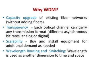
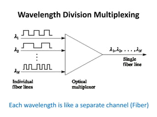
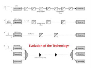
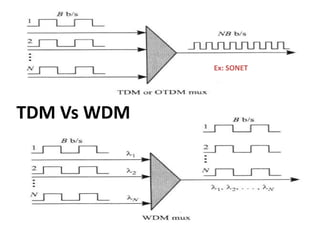
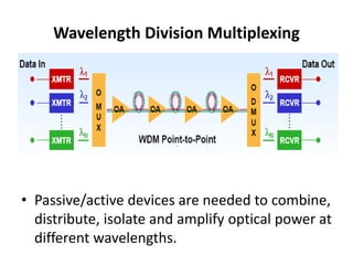
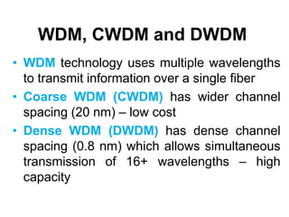
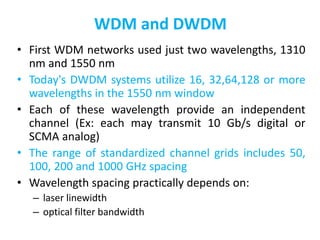
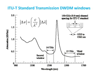
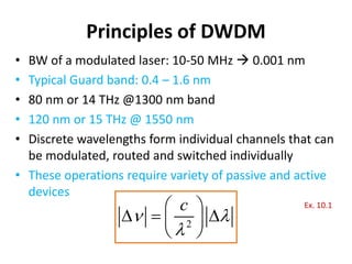
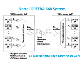
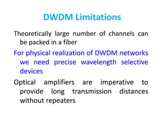
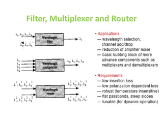
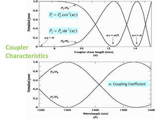
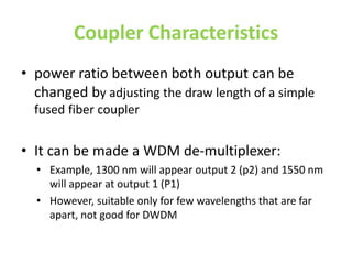
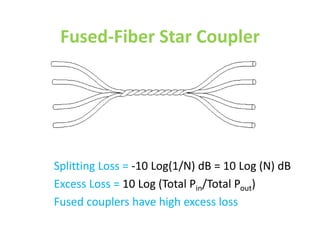
WDM Concept and Components
18ECC302J: Microwave & Optical Communications
Part 1: WDM Concept
Why WDM?
• Capacity upgrade of existing fiber networks
(without adding fibers)
• Transparency - Each optical channel can carry
any transmission format (different asynchronous
bit rates, analog or digital)
• Scalability - Buy and install equipment for
additional demand as needed
• Wavelength Routing and Switching: Wavelength
is used as another dimension to time and space
Wavelength Division Multiplexing
Each wavelength is like a separate channel (Fiber)
Evolution of the Technology
TDM Vs WDM
Ex: SONET
Wavelength Division Multiplexing
• Passive/active devices are needed to combine,
distribute, isolate and amplify optical power at
different wavelengths.
WDM, CWDM and DWDM
• WDM technology uses multiple wavelengths
to transmit information over a single fiber
• Coarse WDM (CWDM) has wider channel
spacing (20 nm) – low cost
• Dense WDM (DWDM) has dense channel
spacing (0.8 nm) which allows simultaneous
transmission of 16+ wavelengths – high
capacity
WDM and DWDM
• First WDM networks used just two wavelengths, 1310
nm and 1550 nm
• Today's DWDM systems utilize 16, 32,64,128 or more
wavelengths in the 1550 nm window
• Each of these wavelength provide an independent
channel (Ex: each may transmit 10 Gb/s digital or
SCMA analog)
• The range of standardized channel grids includes 50,
100, 200 and 1000 GHz spacing
• Wavelength spacing practically depends on:
– laser linewidth
– optical filter bandwidth
ITU-T Standard Transmission DWDM windows
2
c
 

 
  
 
 
Principles of DWDM
• BW of a modulated laser: 10-50 MHz  0.001 nm
• Typical Guard band: 0.4 – 1.6 nm
• 80 nm or 14 THz @1300 nm band
• 120 nm or 15 THz @ 1550 nm
• Discrete wavelengths form individual channels that can
be modulated, routed and switched individually
• These operations require variety of passive and active
devices
2
c
 

 
  
 
 
Ex. 10.1
Nortel OPTERA 640 System
64 wavelengths each carrying 10 Gb/s
DWDM Limitations
Theoretically large number of channels can
be packed in a fiber
For physical realization of DWDM networks
we need precise wavelength selective
devices
Optical amplifiers are imperative to
provide long transmission distances
without repeaters
Part II: WDM Devices
Key Components for WDM
Passive Optical Components
Wavelength Selective Splitters
Wavelength Selective Couplers
Active Optical Components
Tunable Optical Filter
Tunable Source
Optical amplifier
Add-drop Multiplexer and De-multiplexer
Photo Detector Responsivity
Photo detectors are
sensitive over wide
spectrum (600 nm).
Hence, narrow optical
filters needed to
separate channels
before the detection
in DWDM systems
Passive Devices
• These operate completely in the optical
domain (no O/E conversion) and does not need
electrical power
• Split/combine light stream Ex: N X N couplers,
power splitters, power taps and star couplers
• Technologies: - Fiber based or
– Optical waveguides based
– Micro (Nano) optics based
• Fabricated using optical fiber or waveguide
(with special material like InP, LiNbO3)
Passive Components
 Coupler: versatile device used as a building block for
several other optical devices
 Isolator: used in systems at the output of amplifiers and
lasers to prevent reflections
 Filter: to multiplex and demultiplex wavelengths in a
WDM system, and to provide equalization of the gain
and filtering of noise in optical amplifier
 MUX & DEMUX: MUX combines signals at different
wavelengths on its input ports onto a common output
port, DEMUX performs the opposite function
Filter, Multiplexer and Router
Basic Star Coupler
• Can be wavelength selective/nonselective
• Up to N =M = 64, typically N, M < 10
May have N inputs and M outputs
Fused-Biconical Coupler or
Directional Coupler
• P3, P4 extremely low ( -70 dB below Po)
• Coupling / Splitting Ratio = P2/(P1+P2)
• If P1=P2  It is called 3-dB coupler
Coupler
• Fabricated by twisting together, melting and
pulling together two single mode fibers
• They get fused together over length W;
tapered section of length L; total draw length
= L+W
• Significant decrease in V-number in the
coupling region; energy in the core leak out
and gradually couples into the second fibre
Definitions
2 1 2
Splitting (Coupling) Rat = )
i (
o P P P

0 1 2
=10 Log
Excess Lo [
ss ( ]
)
P P P

=1
In 0
sert Log[
ion Loss ]
in out
P P
3 0
= 10 Lo
Crosstalk g(P P )
Coupler
Characteristics
)
(
sin 2
0
2 z
P
P 

)
(
cos2
0
1 z
P
P 

: Coupling Coefficient
Coupler Characteristics
• power ratio between both output can be
changed by adjusting the draw length of a simple
fused fiber coupler
• It can be made a WDM de-multiplexer:
• Example, 1300 nm will appear output 2 (p2) and 1550 nm
will appear at output 1 (P1)
• However, suitable only for few wavelengths that are far
apart, not good for DWDM
Wavelength Selective Devices
These perform their operation on the incoming
optical signal as a function of the wavelength
Examples:
• Wavelength add/drop multiplexers
• Wavelength selective optical combiners/splitters
• Wavelength selective switches and routers
Fused-Fiber Star Coupler
Splitting Loss = -10 Log(1/N) dB = 10 Log (N) dB
Excess Loss = 10 Log (Total Pin/Total Pout)
Fused couplers have high excess loss
8x8 Bi-directional Star Coupler by Cascading
3-stages of 3-dB Couplers
c 2
Number of 3-dB Cou
N
N = log N
2
plers (12 = 4 X 3)
Try Ex. 10.5
1, 2
1, 2
1, 2 5, 6
3, 4 7, 8
Passive Non-Reciprocal Devices
• Types
– Isolators
– Faraday Rotators
– Circulators
30
Isolators and Circulators
(Nonreciprocal devices)
Isolators are for transmitter, circulators are for add and
drop or others.
The insertion loss should be small ~ 1dB
A circulator is similar to an isolator except it has multiple
ports.
Isolators
• Transmit in one direction only
• Avoid reflection of laser – or any reflection
• One input, one output or multiple ports
• Key parameters are insertion loss and excess
loss
• Example of circulators:
Isolators - Passive Non-Reciprocal Device
 Transmit in one direction only
 Avoid reflection of laser – or any reflection
 One input, one output or multiple ports
 Key parameters are insertion loss and excess loss
 Example: circulator
Operation of Isolators
Only Ex exists
State of polarization is fixed (SOP)
Rotator rotates by 45 degree
Operation of Isolators – more realistic
Polarization Independent Isolator
Half-wavelength plates are used to rotate 45 degree
The Spatial-walk-off polarizer splits the signal into two orthogonally polarized signals
Operation of Isolators
Interferometers
Interferometer
An interferometric device uses 2 interfering paths of
different lengths to resolve wavelengths
Typical configuration: two 3-dB directional couplers
connected with 2 paths having different lengths
Applications:
— wideband filters (coarse WDM) that separate signals
at1300 nm from those at 1550 nm
— narrowband filters: filter bandwidth depends on the
number of cascades (i.e. the number of 3-dB couplers
connected)
Basic Mach-Zehnder Interferometer
Phase shift of the propagating wave increases with L,
Constructive or destructive interference depending on L
Mach-Zehnder Interferometer
Phase shift at the output due to the propagation
path length difference:
If the power from both inputs (at different
wavelengths) to be added at output port 2, then,
1 2
1 1
2 eff
n L
 
 
 
  
 
 
2 eff
n
L



  
Four-Channel Wavelength Multiplexer
• By appropriately selecting ΔL, wavelength
multiplexing/de-multiplexing can be achieved
MZI- Demux Example
42
Fabry-Perot Filters
This filter is called Fabry-Perot interferometer or etalon.
Principle of Operation
The wavelengths for which the cavity length is an integral multiple of half
the wavelength in the cavity are called resonant wavelengths.

WDM.ppt

  • 1.
    WDM Concept andComponents 18ECC302J: Microwave & Optical Communications
  • 2.
    Part 1: WDMConcept
  • 3.
    Why WDM? • Capacityupgrade of existing fiber networks (without adding fibers) • Transparency - Each optical channel can carry any transmission format (different asynchronous bit rates, analog or digital) • Scalability - Buy and install equipment for additional demand as needed • Wavelength Routing and Switching: Wavelength is used as another dimension to time and space
  • 4.
    Wavelength Division Multiplexing Eachwavelength is like a separate channel (Fiber)
  • 5.
    Evolution of theTechnology
  • 6.
  • 7.
    Wavelength Division Multiplexing •Passive/active devices are needed to combine, distribute, isolate and amplify optical power at different wavelengths.
  • 8.
    WDM, CWDM andDWDM • WDM technology uses multiple wavelengths to transmit information over a single fiber • Coarse WDM (CWDM) has wider channel spacing (20 nm) – low cost • Dense WDM (DWDM) has dense channel spacing (0.8 nm) which allows simultaneous transmission of 16+ wavelengths – high capacity
  • 9.
    WDM and DWDM •First WDM networks used just two wavelengths, 1310 nm and 1550 nm • Today's DWDM systems utilize 16, 32,64,128 or more wavelengths in the 1550 nm window • Each of these wavelength provide an independent channel (Ex: each may transmit 10 Gb/s digital or SCMA analog) • The range of standardized channel grids includes 50, 100, 200 and 1000 GHz spacing • Wavelength spacing practically depends on: – laser linewidth – optical filter bandwidth
  • 10.
    ITU-T Standard TransmissionDWDM windows 2 c            
  • 11.
    Principles of DWDM •BW of a modulated laser: 10-50 MHz  0.001 nm • Typical Guard band: 0.4 – 1.6 nm • 80 nm or 14 THz @1300 nm band • 120 nm or 15 THz @ 1550 nm • Discrete wavelengths form individual channels that can be modulated, routed and switched individually • These operations require variety of passive and active devices 2 c             Ex. 10.1
  • 12.
    Nortel OPTERA 640System 64 wavelengths each carrying 10 Gb/s
  • 13.
    DWDM Limitations Theoretically largenumber of channels can be packed in a fiber For physical realization of DWDM networks we need precise wavelength selective devices Optical amplifiers are imperative to provide long transmission distances without repeaters
  • 14.
    Part II: WDMDevices
  • 15.
    Key Components forWDM Passive Optical Components Wavelength Selective Splitters Wavelength Selective Couplers Active Optical Components Tunable Optical Filter Tunable Source Optical amplifier Add-drop Multiplexer and De-multiplexer
  • 16.
    Photo Detector Responsivity Photodetectors are sensitive over wide spectrum (600 nm). Hence, narrow optical filters needed to separate channels before the detection in DWDM systems
  • 17.
    Passive Devices • Theseoperate completely in the optical domain (no O/E conversion) and does not need electrical power • Split/combine light stream Ex: N X N couplers, power splitters, power taps and star couplers • Technologies: - Fiber based or – Optical waveguides based – Micro (Nano) optics based • Fabricated using optical fiber or waveguide (with special material like InP, LiNbO3)
  • 18.
    Passive Components  Coupler:versatile device used as a building block for several other optical devices  Isolator: used in systems at the output of amplifiers and lasers to prevent reflections  Filter: to multiplex and demultiplex wavelengths in a WDM system, and to provide equalization of the gain and filtering of noise in optical amplifier  MUX & DEMUX: MUX combines signals at different wavelengths on its input ports onto a common output port, DEMUX performs the opposite function
  • 19.
  • 20.
    Basic Star Coupler •Can be wavelength selective/nonselective • Up to N =M = 64, typically N, M < 10 May have N inputs and M outputs
  • 21.
    Fused-Biconical Coupler or DirectionalCoupler • P3, P4 extremely low ( -70 dB below Po) • Coupling / Splitting Ratio = P2/(P1+P2) • If P1=P2  It is called 3-dB coupler
  • 22.
    Coupler • Fabricated bytwisting together, melting and pulling together two single mode fibers • They get fused together over length W; tapered section of length L; total draw length = L+W • Significant decrease in V-number in the coupling region; energy in the core leak out and gradually couples into the second fibre
  • 23.
    Definitions 2 1 2 Splitting(Coupling) Rat = ) i ( o P P P  0 1 2 =10 Log Excess Lo [ ss ( ] ) P P P  =1 In 0 sert Log[ ion Loss ] in out P P 3 0 = 10 Lo Crosstalk g(P P )
  • 24.
    Coupler Characteristics ) ( sin 2 0 2 z P P  ) ( cos2 0 1 z P P   : Coupling Coefficient
  • 25.
    Coupler Characteristics • powerratio between both output can be changed by adjusting the draw length of a simple fused fiber coupler • It can be made a WDM de-multiplexer: • Example, 1300 nm will appear output 2 (p2) and 1550 nm will appear at output 1 (P1) • However, suitable only for few wavelengths that are far apart, not good for DWDM
  • 26.
    Wavelength Selective Devices Theseperform their operation on the incoming optical signal as a function of the wavelength Examples: • Wavelength add/drop multiplexers • Wavelength selective optical combiners/splitters • Wavelength selective switches and routers
  • 27.
    Fused-Fiber Star Coupler SplittingLoss = -10 Log(1/N) dB = 10 Log (N) dB Excess Loss = 10 Log (Total Pin/Total Pout) Fused couplers have high excess loss
  • 28.
    8x8 Bi-directional StarCoupler by Cascading 3-stages of 3-dB Couplers c 2 Number of 3-dB Cou N N = log N 2 plers (12 = 4 X 3) Try Ex. 10.5 1, 2 1, 2 1, 2 5, 6 3, 4 7, 8
  • 29.
    Passive Non-Reciprocal Devices •Types – Isolators – Faraday Rotators – Circulators
  • 30.
    30 Isolators and Circulators (Nonreciprocaldevices) Isolators are for transmitter, circulators are for add and drop or others. The insertion loss should be small ~ 1dB A circulator is similar to an isolator except it has multiple ports.
  • 31.
    Isolators • Transmit inone direction only • Avoid reflection of laser – or any reflection • One input, one output or multiple ports • Key parameters are insertion loss and excess loss • Example of circulators:
  • 32.
    Isolators - PassiveNon-Reciprocal Device  Transmit in one direction only  Avoid reflection of laser – or any reflection  One input, one output or multiple ports  Key parameters are insertion loss and excess loss  Example: circulator
  • 33.
    Operation of Isolators OnlyEx exists State of polarization is fixed (SOP) Rotator rotates by 45 degree
  • 34.
    Operation of Isolators– more realistic Polarization Independent Isolator Half-wavelength plates are used to rotate 45 degree The Spatial-walk-off polarizer splits the signal into two orthogonally polarized signals
  • 35.
  • 36.
  • 37.
    Interferometer An interferometric deviceuses 2 interfering paths of different lengths to resolve wavelengths Typical configuration: two 3-dB directional couplers connected with 2 paths having different lengths Applications: — wideband filters (coarse WDM) that separate signals at1300 nm from those at 1550 nm — narrowband filters: filter bandwidth depends on the number of cascades (i.e. the number of 3-dB couplers connected)
  • 38.
    Basic Mach-Zehnder Interferometer Phaseshift of the propagating wave increases with L, Constructive or destructive interference depending on L
  • 39.
    Mach-Zehnder Interferometer Phase shiftat the output due to the propagation path length difference: If the power from both inputs (at different wavelengths) to be added at output port 2, then, 1 2 1 1 2 eff n L              2 eff n L      
  • 40.
    Four-Channel Wavelength Multiplexer •By appropriately selecting ΔL, wavelength multiplexing/de-multiplexing can be achieved
  • 41.
  • 42.
    42 Fabry-Perot Filters This filteris called Fabry-Perot interferometer or etalon. Principle of Operation The wavelengths for which the cavity length is an integral multiple of half the wavelength in the cavity are called resonant wavelengths.