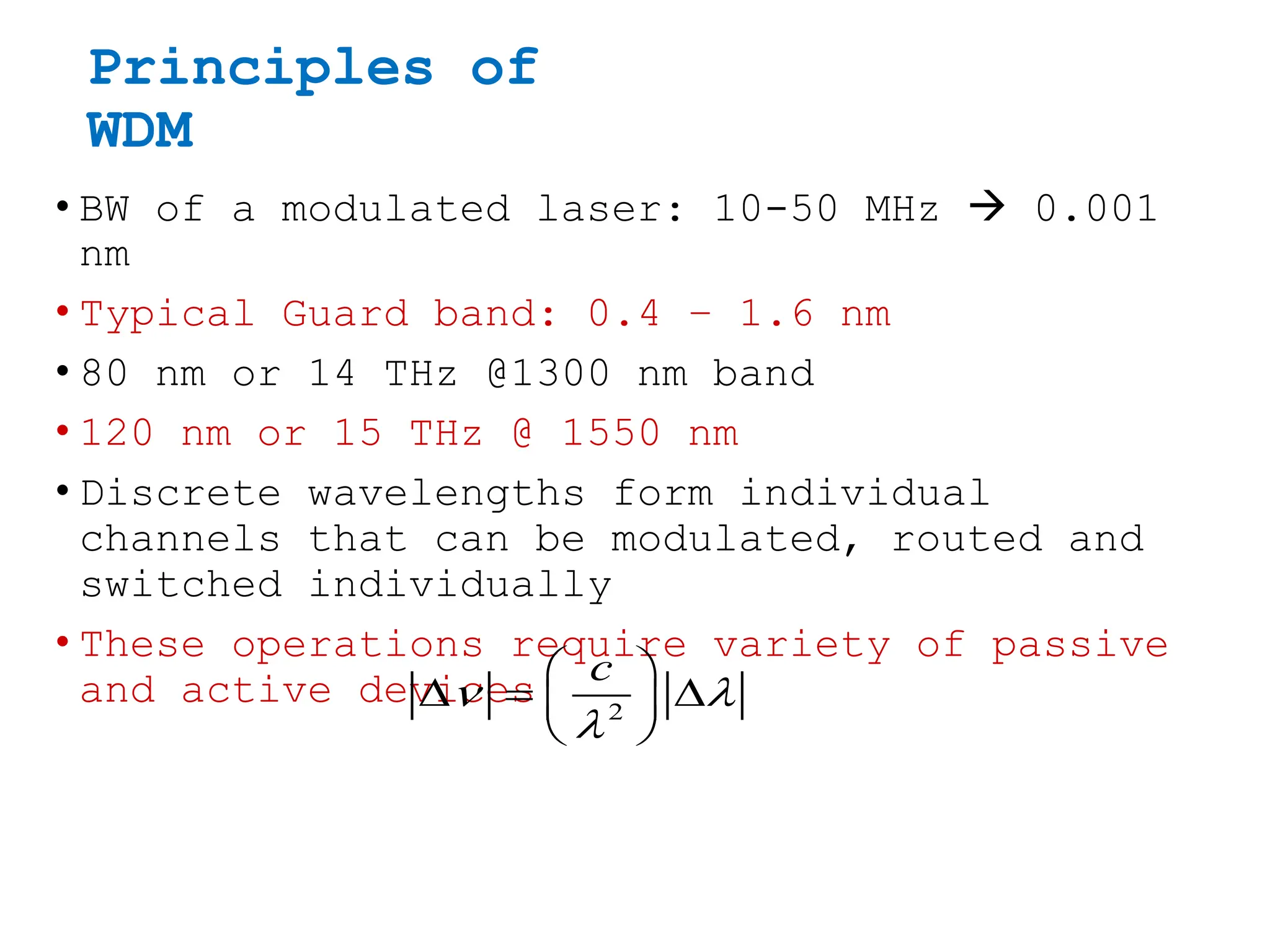
OFC Systems
Module 3
WDM CONCEPTS AND COMPONENTS
By
Dr. Venkateswara Rao Kolli
Associate Professor
ECE,MCE.
Syllabus
1.WDM concepts,
2.Overview of WDM operation principles,
3.WDM standards,
4.Mach-Zehender Interferometer
Multiplexer,
6.Isolators and circulators,
7.Direct thin film filters,
8.Active optical components
Evolution of the Technology
1.WDM concepts
Features of WDM
Important advantages or features of WDM are as
mentioned below –
1. Capacity upgrade : Each wavelength supports
independent data rate in Gbps.
2. Transparency : WDM can carry fast asynchronous,
slow synchronous, synchronous analog and digital data.
3. Wavelength routing : Link capacity and flexibility
can be increased by using multiple wavelength.
4. Wavelength switching : WDM can add or drop
multiplexers, cross connects and wavelength converters
Why WDM?
Each wavelength is like a separate channel (fiber)
Wavelength Division Multiplexing
WDM
concepts(contd…)
WDM, CWDM and DWDM
• WDM technology uses multiple wavelengths to transmit
information over a single fiber.
• Coarse WDM (CWDM) has wider channel spacing (20 nm) – low
cost.
• Dense WDM (DWDM) has dense channel spacing (0.8 nm) which
allows simultaneous transmission of 16+ wavelengths – high
capacity
WDM and DWDM
• First WDM networks used just two wavelengths,
1310 nm and 1550 nm.
• Today's DWDM systems utilize 16, 32,64,128 or
more wavelengths in the 1550 nm window.
• Each of these wavelength provide an independent
channel (Ex: each may transmit 10 Gb/s digital
or SCMA analog).
• The range of standardized channel grids
includes 50, 100, 200 and 1000 GHz spacing.
• Wavelength spacing practically depends on:
• laser line width
• optical filter bandwidth
Principles of
WDM
• BW of a modulated laser: 10-50 MHz  0.001
nm
• Typical Guard band: 0.4 – 1.6 nm
• 80 nm or 14 THz @1300 nm band
• 120 nm or 15 THz @ 1550 nm
• Discrete wavelengths form individual
channels that can be modulated, routed and
switched individually
• These operations require variety of passive
and active devices 2
c
 

 
  
 
 
DWDM Limitations
• Theoretically large number of channels can be
packed in a fiber
• For physical realization of DWDM
networks we need precise wavelength
selective devices
• Optical amplifiers are imperative to
provide long transmission distances
without repeaters
•Optical signals of different wavelength (1300-1600 nm) can
propagate without interfering with each other.
•The scheme of combining a number of wavelengths over a single
fiber is called wavelength division multiplexing (WDM).
•Each input is generated by a separate optical source with a
unique wavelength.
•An optical multiplexer couples light from individual sources
to the transmitting fiber.
•At the receiving station, an optical demultiplexer is required
to separate the different carriers before photodetection of
individual signals.
2.Overview of WDM operation
principles
3.ITU-T Standard Transmission DWDM
windows
4.Mach-Zehnder
Interferometer Multiplexer
Phase shift of the propagating wave increases
Constructive or destructive interference depe
These
devices can
be either
active or
passive.
A layout of
2 x 2
passive MZI
is shown in
Fig.
It consists
of three
stages
a) 3-dB
splitter
b) Phase
shifter
c)3-dB
Combiner.
MZI Multiplexer (contd…)
Mach-Zehnder interferometry is used to make
wavelength dependent multiplexers.
•Initially a 3 dB directional coupler is
used to split input signals.
•The middle stage, in which one of waveguide
is longer by ΔL to given a wavelength
dependent phase shift between the two arms.
•The third stage is a dB coupler which
recombines the signals at output.
•Thus, input beam is splitted an phase shift
it introduced in one of the paths, the
recombined signals will be in phase at one
output and out of phase at other output.
•The output will be available in only one
port
MZI Multiplexer (contd…)
Phase shift at the output due to the
propagation
path length difference:
If the power from both inputs (at
different wavelengths) to be added
at output port 2, then,
1 2
1 1
2 eff
n L
 
 
 
  
 
 
2 eff
n
L



  
MZI Multiplexer
(contd…)
Four-Channel Wavelength
Multiplexer
• By appropriately selecting ΔL, wavelength
multiplexing/de-multiplexing can be achieved
MZI- Demux Example
5.Optical Add/Drop Multiplexer
• As add/drop multiplexer is essentially a
form of a wavelength router with one input
port and one output port with an additional
local port where wavelengths are added
to/dropped from incoming light signal.
• It is an application of optical filter in
optical networks.
• Fiber grating devices are used for add/drop
functions.
• Many variations of add/drop element can be
realized by using gratings in combination
6.Isolator
• An isolator is a passive non-reciprocal device.
• It allows transmission in one direction through it and
blocks all transmission in other direction.
• Isolator are used in systems before optical amplifiers
and lasers mainly to prevent reflections from entering
these devices otherwise performance will degrade.
• Important parameters of an isolator are its insertion
loss (in forward direction) and isolation (in reverse
direction).
• The insertion loss should be as small as possible
while isolation should be as large as possible.
• The typical insertion loss is around 1 dB and
isolation is around 40 to 50 dB.
Principle of
operation
• Isolator works on the principle of state
of polarization (SOP) of light in a
single mode fibers.
• The state of polarization (SOP) refers to
the orientation of its electric field
vector on a plane that is orthogonal to
its direction of propagation.
• The electric field can be expressed as
linear combination of two orthogonal
linear polarization supported by fiber.
• These two polarization modes are
horizontal and vertical modes.
Principle of operation(contd…)
• Let input light signal has vertical state of
polarization (SOP) and blocks energy in horizontal SOP.
• The polarizer is followed by Faraday rotator.
• Faraday rotator is an asymmetric device which rotates
the SOP clockwise by 45o in both direction of
propagation.
• The polarizer after Faraday rotator passes only SOPs
with 45o orientation.
• In this way light signal from left to right is passed
through the device without any loss.
• Light entering the device from right due to reflection,
7.Circulator
• A three-part circulator is shown in Fig. 7.5.1.
Signals of different wavelengths are entered at a
port and sends them out at next port.
• All the wavelengths are passed to port-2.
• If port-2 absorbs any specific wavelength then
remaining wavelengths are reflected and sends them to
Circulators are used to implement demultiplexer using
∂ fiber Bragg grating forextracting a desired
wavelength.
The wavelength satisfying the Bragg condition of
grating gets reflected and exits at next port.
Fig. 7.5.2 illustrates the concept of demultiplexer
function using a fiber grating and an optical
circulator.
Here, from all the wavelengths only λ3 is to be
extracted.
The circulator takes four wavelengths λ1, λ2, λ3 and
Circulator(contd…)
8.Dielectric Thin-Film Filter
(TFF)
Dielectric Thin-Film Filter
(TFF)(contd…)
References
TEXT BOOKS:
1. Optical Fiber Communication – Gerd Keiser, 4th
Ed., MGH, 2008.
2. Optical Fiber Communications– – John M. Senior,
Pearson Education. 3rd Impression, 2007.

Module 3.WDM CONCEPTS AND COMPONENTS.pptx

  • 1.
    OFC Systems Module 3 WDMCONCEPTS AND COMPONENTS By Dr. Venkateswara Rao Kolli Associate Professor ECE,MCE.
  • 2.
    Syllabus 1.WDM concepts, 2.Overview ofWDM operation principles, 3.WDM standards, 4.Mach-Zehender Interferometer Multiplexer, 6.Isolators and circulators, 7.Direct thin film filters, 8.Active optical components
  • 3.
    Evolution of theTechnology 1.WDM concepts
  • 4.
    Features of WDM Importantadvantages or features of WDM are as mentioned below – 1. Capacity upgrade : Each wavelength supports independent data rate in Gbps. 2. Transparency : WDM can carry fast asynchronous, slow synchronous, synchronous analog and digital data. 3. Wavelength routing : Link capacity and flexibility can be increased by using multiple wavelength. 4. Wavelength switching : WDM can add or drop multiplexers, cross connects and wavelength converters Why WDM?
  • 5.
    Each wavelength islike a separate channel (fiber) Wavelength Division Multiplexing
  • 6.
    WDM concepts(contd…) WDM, CWDM andDWDM • WDM technology uses multiple wavelengths to transmit information over a single fiber. • Coarse WDM (CWDM) has wider channel spacing (20 nm) – low cost. • Dense WDM (DWDM) has dense channel spacing (0.8 nm) which allows simultaneous transmission of 16+ wavelengths – high capacity
  • 7.
    WDM and DWDM •First WDM networks used just two wavelengths, 1310 nm and 1550 nm. • Today's DWDM systems utilize 16, 32,64,128 or more wavelengths in the 1550 nm window. • Each of these wavelength provide an independent channel (Ex: each may transmit 10 Gb/s digital or SCMA analog). • The range of standardized channel grids includes 50, 100, 200 and 1000 GHz spacing. • Wavelength spacing practically depends on: • laser line width • optical filter bandwidth
  • 8.
    Principles of WDM • BWof a modulated laser: 10-50 MHz  0.001 nm • Typical Guard band: 0.4 – 1.6 nm • 80 nm or 14 THz @1300 nm band • 120 nm or 15 THz @ 1550 nm • Discrete wavelengths form individual channels that can be modulated, routed and switched individually • These operations require variety of passive and active devices 2 c            
  • 9.
    DWDM Limitations • Theoreticallylarge number of channels can be packed in a fiber • For physical realization of DWDM networks we need precise wavelength selective devices • Optical amplifiers are imperative to provide long transmission distances without repeaters
  • 10.
    •Optical signals ofdifferent wavelength (1300-1600 nm) can propagate without interfering with each other. •The scheme of combining a number of wavelengths over a single fiber is called wavelength division multiplexing (WDM). •Each input is generated by a separate optical source with a unique wavelength. •An optical multiplexer couples light from individual sources to the transmitting fiber. •At the receiving station, an optical demultiplexer is required to separate the different carriers before photodetection of individual signals. 2.Overview of WDM operation principles
  • 11.
  • 12.
    4.Mach-Zehnder Interferometer Multiplexer Phase shiftof the propagating wave increases Constructive or destructive interference depe These devices can be either active or passive. A layout of 2 x 2 passive MZI is shown in Fig. It consists of three stages a) 3-dB splitter b) Phase shifter c)3-dB Combiner.
  • 13.
    MZI Multiplexer (contd…) Mach-Zehnderinterferometry is used to make wavelength dependent multiplexers. •Initially a 3 dB directional coupler is used to split input signals. •The middle stage, in which one of waveguide is longer by ΔL to given a wavelength dependent phase shift between the two arms. •The third stage is a dB coupler which recombines the signals at output. •Thus, input beam is splitted an phase shift it introduced in one of the paths, the recombined signals will be in phase at one output and out of phase at other output. •The output will be available in only one port
  • 14.
  • 15.
  • 16.
    Phase shift atthe output due to the propagation path length difference: If the power from both inputs (at different wavelengths) to be added at output port 2, then, 1 2 1 1 2 eff n L              2 eff n L       MZI Multiplexer (contd…)
  • 17.
    Four-Channel Wavelength Multiplexer • Byappropriately selecting ΔL, wavelength multiplexing/de-multiplexing can be achieved
  • 18.
  • 20.
    5.Optical Add/Drop Multiplexer •As add/drop multiplexer is essentially a form of a wavelength router with one input port and one output port with an additional local port where wavelengths are added to/dropped from incoming light signal. • It is an application of optical filter in optical networks. • Fiber grating devices are used for add/drop functions. • Many variations of add/drop element can be realized by using gratings in combination
  • 21.
    6.Isolator • An isolatoris a passive non-reciprocal device. • It allows transmission in one direction through it and blocks all transmission in other direction. • Isolator are used in systems before optical amplifiers and lasers mainly to prevent reflections from entering these devices otherwise performance will degrade. • Important parameters of an isolator are its insertion loss (in forward direction) and isolation (in reverse direction). • The insertion loss should be as small as possible while isolation should be as large as possible. • The typical insertion loss is around 1 dB and isolation is around 40 to 50 dB.
  • 22.
    Principle of operation • Isolatorworks on the principle of state of polarization (SOP) of light in a single mode fibers. • The state of polarization (SOP) refers to the orientation of its electric field vector on a plane that is orthogonal to its direction of propagation. • The electric field can be expressed as linear combination of two orthogonal linear polarization supported by fiber. • These two polarization modes are horizontal and vertical modes.
  • 23.
    Principle of operation(contd…) •Let input light signal has vertical state of polarization (SOP) and blocks energy in horizontal SOP. • The polarizer is followed by Faraday rotator. • Faraday rotator is an asymmetric device which rotates the SOP clockwise by 45o in both direction of propagation. • The polarizer after Faraday rotator passes only SOPs with 45o orientation. • In this way light signal from left to right is passed through the device without any loss. • Light entering the device from right due to reflection,
  • 24.
    7.Circulator • A three-partcirculator is shown in Fig. 7.5.1. Signals of different wavelengths are entered at a port and sends them out at next port. • All the wavelengths are passed to port-2. • If port-2 absorbs any specific wavelength then remaining wavelengths are reflected and sends them to
  • 26.
    Circulators are usedto implement demultiplexer using ∂ fiber Bragg grating forextracting a desired wavelength. The wavelength satisfying the Bragg condition of grating gets reflected and exits at next port. Fig. 7.5.2 illustrates the concept of demultiplexer function using a fiber grating and an optical circulator. Here, from all the wavelengths only λ3 is to be extracted. The circulator takes four wavelengths λ1, λ2, λ3 and Circulator(contd…)
  • 27.
  • 28.
  • 29.
    References TEXT BOOKS: 1. OpticalFiber Communication – Gerd Keiser, 4th Ed., MGH, 2008. 2. Optical Fiber Communications– – John M. Senior, Pearson Education. 3rd Impression, 2007.

Editor's Notes