Fluid Machinery
• Fluidmachinery systems are mechanical setups that utilize fluids
(liquids or gases) to transfer energy or perform work.
• Fluid machinery is generally divided into hydraulic systems (dealing
with liquids) and pneumatic systems (dealing with gases).
3.
Different Types ofFluid Machinery
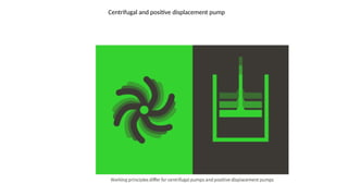
A. Pump
• Function: Pumps are used to move liquids in hydraulic systems.
• Types:
• Centrifugal Pump: Converts rotational energy into pressure by increasing fluid
velocity.
• Positive Displacement Pump: Moves a fixed volume of fluid through the system,
regardless of pressure.
Reciprocating Pump: A positive displacement pump that uses a back-and-forth
(reciprocating) motion of a piston within a cylinder to move fluids. The piston moves
in one direction to draw in fluid, and in the opposite direction, it forces the fluid out,
delivering it to the system. This pump is ideal for applications requiring high pressure
and precise fluid delivery.
4.
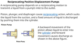
Reciprocating Positive DisplacementPumps
A reciprocating pump depends on a reciprocating motion to
transmit a liquid from a pump’s inlet to the outlet.
Piston, plunger, and diaphragm cause reciprocating action, which sucks
the liquid from the suction, and a fixed amount of liquid is discharged
by pushing them into the cylinder.
A backward movement of the
piston allows liquid to enter into
the cylinder and forward
movement causes discharge as
shown in the above figure.
5.
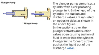
The plunger pumpcomprises a
cylinder with a reciprocating
plunger in it. In the head of the
cylinder, the suction and
discharge valves are mounted
on opposite sides as shown in
the above figure.
In the suction stroke, the
plunger retracts and suction
valves open causing suction of
fluid to enter into the cylinder.
Plunger in the forward stroke
pushes the liquid out of the
discharge valve.
6.
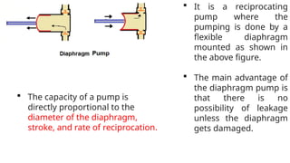
The capacityof a pump is
directly proportional to the
diameter of the diaphragm,
stroke, and rate of reciprocation.
It is a reciprocating
pump where the
pumping is done by a
flexible diaphragm
mounted as shown in
the above figure.
The main advantage of
the diaphragm pump is
that there is no
possibility of leakage
unless the diaphragm
gets damaged.
7.
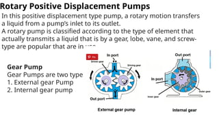
Rotary Positive DisplacementPumps
In this positive displacement type pump, a rotary motion transfers
a liquid from a pump’s inlet to its outlet.
A rotary pump is classified according to the type of element that
actually transmits a liquid that is by a gear, lobe, vane, and screw-
type are popular that are in use.
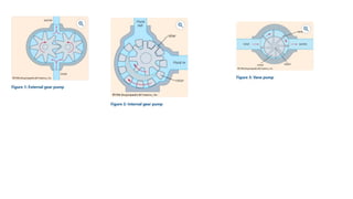
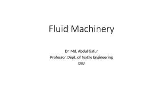
Gear Pump
Gear Pumps are two types.
1. External gear Pump
2. Internal gear pump
8.
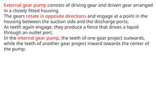
External gear pumpconsists of driving gear and driven gear arranged
in a closely fitted housing.
The gears rotate in opposite directions and engage at a point in the
housing between the suction side and the discharge ports.
As teeth again engage, they produce a force that drives a liquid
through an outlet port.
In the internal gear pump, the teeth of one gear project outwards,
while the teeth of another gear project inward towards the center of
the pump.
9.
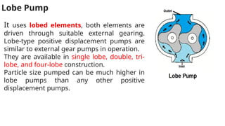
Lobe Pump
It useslobed elements, both elements are
driven through suitable external gearing.
Lobe-type positive displacement pumps are
similar to external gear pumps in operation.
They are available in single lobe, double, tri-
lobe, and four-lobe construction.
Particle size pumped can be much higher in
lobe pumps than any other positive
displacement pumps.
10.
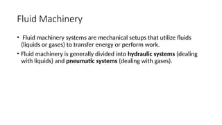
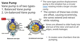
Vane Pump
Vane pumpis of two types-
1. Balanced Vane pump
2. Un-balanced Vane pump
Outlet
The vane-type positive displacement
pump is the simplest has a circular
rotor rotating inside a larger circular
cavity.
• It creates vane chambers that do
pumping.
The centers of these two circles
are offset, causing eccentricity,
the vanes extend and retract
while rotating.
• Vanes are allowed to slide freely into
and out of the rotor and seal on all
edges, avoids leakages.
11.
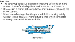
Screw Pump
Thescrew-type positive-displacement pump uses one or more
screws to transfer the liquids or solids across the screw axis.
It rotates in a cylindrical cavity, hence moving material along the
screw spindle.
It has one advantage that the pumped fluid is moving axially
without losing flow rate, without turbulence which eliminates
foaming chances with viscous fluids.
12.
SL Centrifugal PumpReciprocating Pump
1 Simple in construction, because of
less number of parts
Complicated in construction, because of
more numbers of parts.
2 Total weight of the pump is less for
a given discharge.
Total weight of the pump is more for a
given discharge.
3 Suitable for large discharge and
smaller heads.
Suitable for less discharge and higher
heads.
4 Requires less floor area and simple
foundation.
Requires more floor area and higher
heads.
5 Less wear and tear. More wear and tear.
6 Maintenance cost is less. Maintenance cost is more.
7 It can deliver dirty water It cannot deliver dirty water
13.
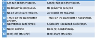
SL Centrifugal PumpReciprocating Pump
7 Can run at higher speeds. Cannot run at higher speeds.
8 Its delivery is continuous. Its delivery is pulsating
9 No air vessels are required. Air vessels are required.
10 Thrust on the crankshaft is
uniform.
Thrust on the crankshaft is not uniform.
11 Operation is quite simple. Much care is required in operation.
12 Needs priming. Does not need priming.
13 It has less efficiency. It has more efficiency.
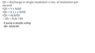
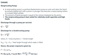
Discharge of ReciprocatingPump
•A = cross-section area of the cylinder
•r = radius of crank
•L = Stroke length, which means travel of piston in each
forward or backward stroke, it equals to 2r, i.e L = 2r [as half
cycle rotation or 180 deg rotation gives one stroke]
•V = volume of discharge in one revolution = area x length = A
x L, m3
•N = RPM, that means rotation per minute or
•N/60 = rotation per second
•Qh = Fluid flow rate per second, m3
/s
16.
Qh = dischargein single revolution x nos. of revolution per
second
•Qh = V x N/60
•Qh = A x L x N/60
•Qh = ALN/60
∴ Qh = ALN / 60
If pump is double acting
Qh= 2ALN/60
17.
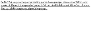
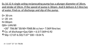
Ex.16.12 A singleacting reciprocating pump has a plunger diameter of 30cm, and
stroke of 20cm. If the speed of pump is 30rpm. And it delivers 6.5 litre/sec of water.
Find co. of discharge and slip of the pump.
18.
Ex.16.12 A singleacting reciprocating pump has a plunger diameter of 30cm,
and stroke of 20cm. If the speed of pump is 30rpm. And it delivers 6.5 litre/sec
of water. Find co. of discharge and slip of the pump.
D= 30 cm
L= 20 cm
N=30rpm
Qth= LAN/60
=20* 706.86*30/60=7068.86 cc/sec= 7.069 litre/sec
Co. of discharge=Qac/Qth = 6.5/7.069=0.92
Slip =(7.07-6.50)/7.07*100 = 8.04 %
A = 3.114* 15* 15= 706.86
19.
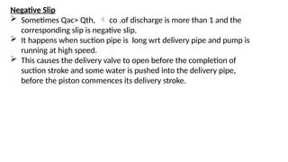
Negative Slip
SometimesQac> Qth, co .of discharge is more than 1 and the
corresponding slip is negative slip.
It happens when suction pipe is long wrt delivery pipe and pump is
running at high speed.
This causes the delivery valve to open before the completion of
suction stroke and some water is pushed into the delivery pipe,
before the piston commences its delivery stroke.
Power required
Specific wt=γ
Suction head = Hs in metre
Delivery Head = Hd in metre
Total head =Hs + Hd
Force acting on piston= γ * (Hs+Hd) * A [ kg/m3 *m *m2=Kg]
Work done, Wd= force *Q
Power required = Wd /75 =9.81
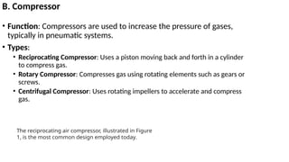
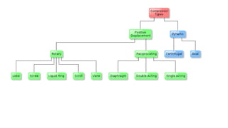
B. Compressor
• Function:Compressors are used to increase the pressure of gases,
typically in pneumatic systems.
• Types:
• Reciprocating Compressor: Uses a piston moving back and forth in a cylinder
to compress gas.
• Rotary Compressor: Compresses gas using rotating elements such as gears or
screws.
• Centrifugal Compressor: Uses rotating impellers to accelerate and compress
gas.
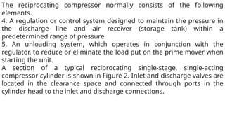
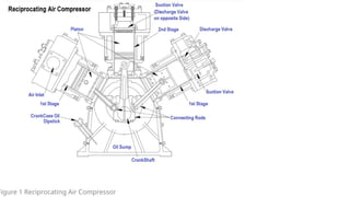
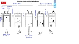
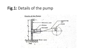
The reciprocating air compressor, illustrated in Figure
1, is the most common design employed today.
26.
The reciprocating compressornormally consists of the following
elements.
1. The compressing element, consisting of air cylinders, heads and
pistons, and air inlet and discharge valves.
2. A system of connecting rods, piston rods, cross-heads, and a
crankshaft and flywheel for transmitting the power developed by the
driving unit to the air cylinder piston.
3. A self-contained lubricating system for bearings, gears, and cylinder
walls, including a reservoir or sump for the lubricating oil, and a pump,
or other means of delivering oil to the various parts. On some
compressors a separate force-fed lubricator is installed to supply oil to
the compressor cylinders.
27.
The reciprocating compressornormally consists of the following
elements.
4. A regulation or control system designed to maintain the pressure in
the discharge line and air receiver (storage tank) within a
predetermined range of pressure.
5. An unloading system, which operates in conjunction with the
regulator, to reduce or eliminate the load put on the prime mover when
starting the unit.
A section of a typical reciprocating single-stage, single-acting
compressor cylinder is shown in Figure 2. Inlet and discharge valves are
located in the clearance space and connected through ports in the
cylinder head to the inlet and discharge connections.
During thesuction stroke the compressor piston starts its downward
stroke and the air under pressure in the clearance space rapidly
expands until the pressure falls below that on the opposite side of
the inlet valve (Figures 2B and 2C).
This difference in pressure causes the inlet valve to open into the
cylinder until the piston reaches the bottom of its stroke (Figure 2C).
During the compression stroke the piston starts upward,
compression begins, and at point D has reached the same pressure
as the compressor intake.
The spring-loaded inlet valve then closes. As the piston continues
upward, air is compressed until the pressure in the cylinder
becomes great enough to open the discharge valve against the
pressure of the valve springs and the pressure of the discharge line
(Figure 2E).
From this point, to the end of the stroke (Figures 2E and 2A), the air
compressed within the cylinder is discharged at practically constant
31.
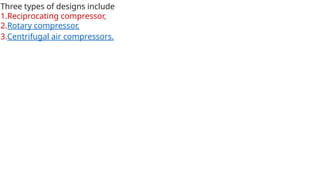
Three types ofdesigns include
1.Reciprocating compressor,
2.Rotary compressor,
3.Centrifugal air compressors.
33.
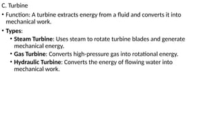
C. Turbine
• Function:A turbine extracts energy from a fluid and converts it into
mechanical work.
• Types:
• Steam Turbine: Uses steam to rotate turbine blades and generate
mechanical energy.
• Gas Turbine: Converts high-pressure gas into rotational energy.
• Hydraulic Turbine: Converts the energy of flowing water into
mechanical work.
34.
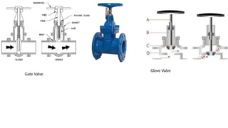
D. Valve
• Function:Controls the flow of fluids in the system, enabling start,
stop, or flow regulation.
• Types:
• Gate Valve: Used to start or stop the fluid flow.
• Globe Valve: Regulates fluid flow.
• Check Valve: Prevents backflow of fluids. Non-returning valve
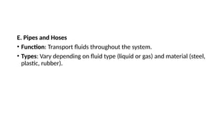
E. Pipes andHoses
• Function: Transport fluids throughout the system.
• Types: Vary depending on fluid type (liquid or gas) and material (steel,
plastic, rubber).
37.
2. Working Principleof Fluid Machinery systems
• Fluid machinery systems work by utilizing fluid properties—mainly
pressure, velocity, and flow rate—to perform mechanical work. These
machines either add energy to the fluid or extract it.
• Energy Addition: Pumps, compressors, and fans increase the energy
of fluids by raising their pressure or velocity.
• Energy Extraction: Turbines extract energy from fluids and convert it
into mechanical work, which can be used to drive other machinery or
generate electricity.
38.
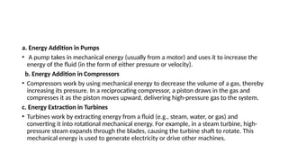
a. Energy Additionin Pumps
• A pump takes in mechanical energy (usually from a motor) and uses it to increase the
energy of the fluid (in the form of either pressure or velocity).
b. Energy Addition in Compressors
• Compressors work by using mechanical energy to decrease the volume of a gas, thereby
increasing its pressure. In a reciprocating compressor, a piston draws in the gas and
compresses it as the piston moves upward, delivering high-pressure gas to the system.
c. Energy Extraction in Turbines
• Turbines work by extracting energy from a fluid (e.g., steam, water, or gas) and
converting it into rotational mechanical energy. For example, in a steam turbine, high-
pressure steam expands through the blades, causing the turbine shaft to rotate. This
mechanical energy is used to generate electricity or drive other machines.
39.
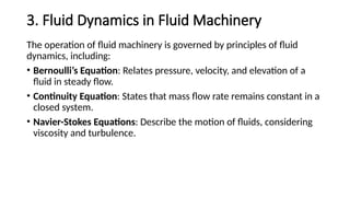
3. Fluid Dynamicsin Fluid Machinery
The operation of fluid machinery is governed by principles of fluid
dynamics, including:
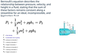
• Bernoulli’s Equation: Relates pressure, velocity, and elevation of a
fluid in steady flow.
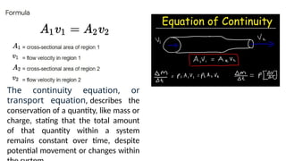
• Continuity Equation: States that mass flow rate remains constant in a
closed system.
• Navier-Stokes Equations: Describe the motion of fluids, considering
viscosity and turbulence.
40.
The continuity equation,or
transport equation, describes the
conservation of a quantity, like mass or
charge, stating that the total amount
of that quantity within a system
remains constant over time, despite
potential movement or changes within
41.
Bernoulli's equation describesthe
relationship between pressure, velocity, and
height in a fluid, stating that the sum of
these factors remains constant along a
streamline for an ideal, incompressible, and
frictionless fluid.
42.
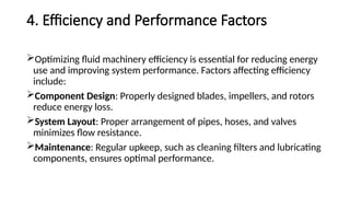
4. Efficiency andPerformance Factors
Optimizing fluid machinery efficiency is essential for reducing energy
use and improving system performance. Factors affecting efficiency
include:
Component Design: Properly designed blades, impellers, and rotors
reduce energy loss.
System Layout: Proper arrangement of pipes, hoses, and valves
minimizes flow resistance.
Maintenance: Regular upkeep, such as cleaning filters and lubricating
components, ensures optimal performance.
43.
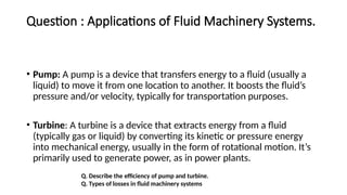
Question : Applicationsof Fluid Machinery Systems.
• Pump: A pump is a device that transfers energy to a fluid (usually a
liquid) to move it from one location to another. It boosts the fluid’s
pressure and/or velocity, typically for transportation purposes.
• Turbine: A turbine is a device that extracts energy from a fluid
(typically gas or liquid) by converting its kinetic or pressure energy
into mechanical energy, usually in the form of rotational motion. It’s
primarily used to generate power, as in power plants.
Q. Describe the efficiency of pump and turbine.
Q. Types of losses in fluid machinery systems
44.
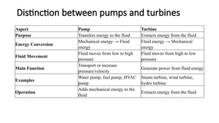
Distinction between pumpsand turbines
Aspect Pump Turbine
Purpose Transfers energy to the fluid Extracts energy from the fluid
Energy Conversion
Mechanical energy → Fluid
energy
Fluid energy → Mechanical
energy
Fluid Movement
Fluid moves from low to high
pressure
Fluid moves from high to low
pressure
Main Function
Transport or increase
pressure/velocity
Generate power from fluid energy
Examples
Water pump, fuel pump, HVAC
pump
Steam turbine, wind turbine,
hydro turbine
Operation
Adds mechanical energy to the
fluid
Extracts energy from the fluid
45.
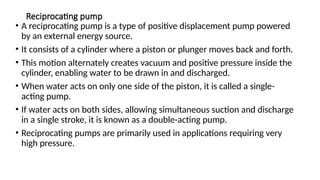
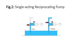
Reciprocating pump
• Areciprocating pump is a type of positive displacement pump powered
by an external energy source.
• It consists of a cylinder where a piston or plunger moves back and forth.
• This motion alternately creates vacuum and positive pressure inside the
cylinder, enabling water to be drawn in and discharged.
• When water acts on only one side of the piston, it is called a single-
acting pump.
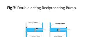
• If water acts on both sides, allowing simultaneous suction and discharge
in a single stroke, it is known as a double-acting pump.
• Reciprocating pumps are primarily used in applications requiring very
high pressure.

![Discharge of Reciprocating Pump
•A = cross-section area of the cylinder
•r = radius of crank
•L = Stroke length, which means travel of piston in each
forward or backward stroke, it equals to 2r, i.e L = 2r [as half
cycle rotation or 180 deg rotation gives one stroke]
•V = volume of discharge in one revolution = area x length = A
x L, m3
•N = RPM, that means rotation per minute or
•N/60 = rotation per second
•Qh = Fluid flow rate per second, m3
/s](https://image.slidesharecdn.com/fluidmachinery1stclasstoday-250502192018-314f32d0/85/Fluid-Machinery-1st-class-today-pptxcccc-15-320.jpg)
![Power required
Specific wt =γ
Suction head = Hs in metre
Delivery Head = Hd in metre
Total head =Hs + Hd
Force acting on piston= γ * (Hs+Hd) * A [ kg/m3 *m *m2=Kg]
Work done, Wd= force *Q
Power required = Wd /75 =9.81](https://image.slidesharecdn.com/fluidmachinery1stclasstoday-250502192018-314f32d0/85/Fluid-Machinery-1st-class-today-pptxcccc-23-320.jpg)