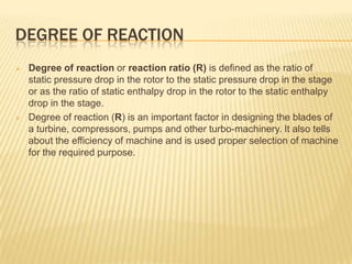
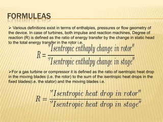
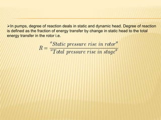
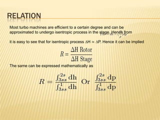
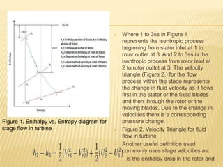
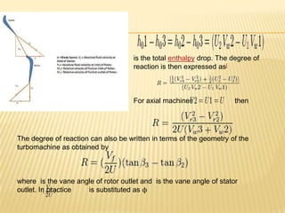
DEGREE OF REACTION
&
IT’S DERIVATIONS
Submitted to: Submitted by
Mr. S S Sandhu Harshit jain Gurjot
singh
11109034 11109031
DEGREE OF REACTION
 Degree of reaction or reaction ratio (R) is defined as the ratio of
static pressure drop in the rotor to the static pressure drop in the stage
or as the ratio of static enthalpy drop in the rotor to the static enthalpy
drop in the stage.
 Degree of reaction (R) is an important factor in designing the blades of
a turbine, compressors, pumps and other turbo-machinery. It also tells
about the efficiency of machine and is used proper selection of machine
for the required purpose.
FORMULEAS
 Various definitions exist in terms of enthalpies, pressures or flow geometry of
the device. In case of turbines, both impulse and reaction machines, Degree of
reaction (R) is defined as the ratio of energy transfer by the change in static head
to the total energy transfer in the rotor i.e.
For a gas turbine or compressor it is defined as the ratio of isentropic heat drop
in the moving blades (i.e. the rotor) to the sum of the isentropic heat drops in the
fixed blades(i.e. the stator) and the moving blades i.e.
In pumps, degree of reaction deals in static and dynamic head. Degree of reaction
is defined as the fraction of energy transfer by change in static head to the total
energy transfer in the rotor i.e.
RELATION
Most turbo machines are efficient to a certain degree and can be
approximated to undergo isentropic process in the stage. Hence from
it is easy to see that for isentropic process ∆H ≃ ∆P. Hence it can be implied
The same can be expressed mathematically as
 Where 1 to 3ss in Figure 1
represents the isentropic process
beginning from stator inlet at 1 to
rotor outlet at 3. And 2 to 3ss is the
isentropic process from rotor inlet at
2 to rotor outlet at 3. The velocity
triangle (Figure 2.) for the flow
process within the stage represents
the change in fluid velocity as it flows
first in the stator or the fixed blades
and then through the rotor or the
moving blades. Due to the change in
velocities there is a corresponding
pressure change.
 Figure 2. Velocity Triangle for fluid
flow in turbine
 Another useful definition used
commonly uses stage velocities as:
 is the enthalpy drop in the rotor and
Figure 1. Enthalpy vs. Entropy diagram for
stage flow in turbine
is the total enthalpy drop. The degree of
reaction is then expressed as[
For axial machines then
The degree of reaction can also be written in terms of the geometry of the
turbomachine as obtained by
where is the vane angle of rotor outlet and is the vane angle of stator
outlet. In practice is substituted as ϕ
CHOICE OF REACTION (R) AND EFFECT
ON EFFICIENCY
 The Figure 3 alongside shows the variation of total-to-static efficiency at different
with the degree of reaction.
 The governing equation is written as
Figure 3. Influence of reaction on total-to-static
efficiency with fixed value of stage loading
factor
where is the stage loading factor.
The diagram shows the optimization of
total - to - static efficiency at a given stage
loading factor, by a suitable choice of reaction.
It is evident from the diagram that for a fixed
stage
loading factor that there is a relatively small
change
in total-to-static efficiency for a wide range of
designs.
50% reaction
The degree of reaction contributes to the stage
efficiency and thus used as a design
parameter. Stages having 50% degree of
reaction are used where the pressure drop is
equally shared by the stator and the rotor for
a turbine.
Figure 4. Velocity triangle for Degree of Reacton
= 1/2 in a turbine
This reduces the tendency of boundary
layer separation from the blade surface
avoiding large stagnation pressure losses.
If R= 1⁄2 then from the relation of degree of
reaction,|C| α2 = β3 and the velocity
triangle(Figure 4.) is symmetric. The
stage enthalpy gets equally distributed in the
stage (Figure 5.) . In addition
the whirl components at are also same at
the inlet of rotor and diffuser.Figure 4. Velocity triangle for
Degree of Reacton = 1/2 in a
turbine
 Reaction less than 50%
 Stage having reaction less than half
suggest that pressure drop or enthalpy
drop in the rotor is less than the pressure
drop in the stator for the turbine. The same
follows for a pump or compressor as
shown in Figure 6. Thus the stator has a
larger contribution to the total work
extracted or work done. From the relation
for degree of reaction, |C| α2 > β3 .
Figure 5. Stage enthalpy diagram for
degree of reaction = 1⁄2 in a turbine and
pump.
 Reaction more than 50%
 Stage having reaction more than half
suggest that pressure drop or
enthalpy drop
 in the rotor is more than the
pressure drop in the stator for the
turbine. The same follows for a
pump or compressor. Thus in this
case the rotor has a larger
contribution to the total work
extracted or work done. From the
relation for degree of reaction,|C| α2
< β3 which is also shown in
corresponding Figure 7.
Figure 6. Stage
enthalpy for
Reaction less than
half
Figure 7. Velocity triangle for
reaction more than 50%.
 Reaction = zero
 This is special case used for impulse
turbine which suggest that entire
pressure drop in the turbine is
obtained in the stator. The stator
performs a nozzle action converting
pressure head to velocity head and
extracting work. It is difficult to
achieve adiabatic expansion in the
impulse stage i.e. expansion only in
the nozzle, due to irreversibility
involved, in actual practice. Figure 8
shows the corresponding enthalpy
drop for the reaction = 0 case.
Figure 8. Stage enthalpy for degree of
reaction =0 in a turbine

Degree of reaction

  • 1.
    DEGREE OF REACTION & IT’SDERIVATIONS Submitted to: Submitted by Mr. S S Sandhu Harshit jain Gurjot singh 11109034 11109031
  • 2.
    DEGREE OF REACTION Degree of reaction or reaction ratio (R) is defined as the ratio of static pressure drop in the rotor to the static pressure drop in the stage or as the ratio of static enthalpy drop in the rotor to the static enthalpy drop in the stage.  Degree of reaction (R) is an important factor in designing the blades of a turbine, compressors, pumps and other turbo-machinery. It also tells about the efficiency of machine and is used proper selection of machine for the required purpose.
  • 3.
    FORMULEAS  Various definitionsexist in terms of enthalpies, pressures or flow geometry of the device. In case of turbines, both impulse and reaction machines, Degree of reaction (R) is defined as the ratio of energy transfer by the change in static head to the total energy transfer in the rotor i.e. For a gas turbine or compressor it is defined as the ratio of isentropic heat drop in the moving blades (i.e. the rotor) to the sum of the isentropic heat drops in the fixed blades(i.e. the stator) and the moving blades i.e.
  • 4.
    In pumps, degreeof reaction deals in static and dynamic head. Degree of reaction is defined as the fraction of energy transfer by change in static head to the total energy transfer in the rotor i.e.
  • 5.
    RELATION Most turbo machinesare efficient to a certain degree and can be approximated to undergo isentropic process in the stage. Hence from it is easy to see that for isentropic process ∆H ≃ ∆P. Hence it can be implied The same can be expressed mathematically as
  • 6.
     Where 1to 3ss in Figure 1 represents the isentropic process beginning from stator inlet at 1 to rotor outlet at 3. And 2 to 3ss is the isentropic process from rotor inlet at 2 to rotor outlet at 3. The velocity triangle (Figure 2.) for the flow process within the stage represents the change in fluid velocity as it flows first in the stator or the fixed blades and then through the rotor or the moving blades. Due to the change in velocities there is a corresponding pressure change.  Figure 2. Velocity Triangle for fluid flow in turbine  Another useful definition used commonly uses stage velocities as:  is the enthalpy drop in the rotor and Figure 1. Enthalpy vs. Entropy diagram for stage flow in turbine
  • 7.
    is the totalenthalpy drop. The degree of reaction is then expressed as[ For axial machines then The degree of reaction can also be written in terms of the geometry of the turbomachine as obtained by where is the vane angle of rotor outlet and is the vane angle of stator outlet. In practice is substituted as ϕ
  • 8.
    CHOICE OF REACTION(R) AND EFFECT ON EFFICIENCY  The Figure 3 alongside shows the variation of total-to-static efficiency at different with the degree of reaction.  The governing equation is written as Figure 3. Influence of reaction on total-to-static efficiency with fixed value of stage loading factor where is the stage loading factor. The diagram shows the optimization of total - to - static efficiency at a given stage loading factor, by a suitable choice of reaction. It is evident from the diagram that for a fixed stage loading factor that there is a relatively small change in total-to-static efficiency for a wide range of designs.
  • 9.
    50% reaction The degreeof reaction contributes to the stage efficiency and thus used as a design parameter. Stages having 50% degree of reaction are used where the pressure drop is equally shared by the stator and the rotor for a turbine. Figure 4. Velocity triangle for Degree of Reacton = 1/2 in a turbine This reduces the tendency of boundary layer separation from the blade surface avoiding large stagnation pressure losses. If R= 1⁄2 then from the relation of degree of reaction,|C| α2 = β3 and the velocity triangle(Figure 4.) is symmetric. The stage enthalpy gets equally distributed in the stage (Figure 5.) . In addition the whirl components at are also same at the inlet of rotor and diffuser.Figure 4. Velocity triangle for Degree of Reacton = 1/2 in a turbine
  • 10.
     Reaction lessthan 50%  Stage having reaction less than half suggest that pressure drop or enthalpy drop in the rotor is less than the pressure drop in the stator for the turbine. The same follows for a pump or compressor as shown in Figure 6. Thus the stator has a larger contribution to the total work extracted or work done. From the relation for degree of reaction, |C| α2 > β3 . Figure 5. Stage enthalpy diagram for degree of reaction = 1⁄2 in a turbine and pump.
  • 11.
     Reaction morethan 50%  Stage having reaction more than half suggest that pressure drop or enthalpy drop  in the rotor is more than the pressure drop in the stator for the turbine. The same follows for a pump or compressor. Thus in this case the rotor has a larger contribution to the total work extracted or work done. From the relation for degree of reaction,|C| α2 < β3 which is also shown in corresponding Figure 7. Figure 6. Stage enthalpy for Reaction less than half Figure 7. Velocity triangle for reaction more than 50%.
  • 12.
     Reaction =zero  This is special case used for impulse turbine which suggest that entire pressure drop in the turbine is obtained in the stator. The stator performs a nozzle action converting pressure head to velocity head and extracting work. It is difficult to achieve adiabatic expansion in the impulse stage i.e. expansion only in the nozzle, due to irreversibility involved, in actual practice. Figure 8 shows the corresponding enthalpy drop for the reaction = 0 case. Figure 8. Stage enthalpy for degree of reaction =0 in a turbine