Reciprocating pump
• Pumpsare used to increase the energy level of
water by virtue of which it can be raised to a
higher level.
• Reciprocating pumps are positive displacement
pump, i.e. initially, a small quantity of liquid is
taken into a chamber and is physically displaced
and forced out with pressure by a moving
mechanical elements.
3.
Reciprocating pump application
•For industrial purposes, they have become
obsolete due to their high initial and
maintenance costs as compared to centrifugal
pumps.
• Small hand operated pumps are still in use that
include well pumps, etc.
• These are useful where high heads are required
with small discharge, as oil drilling operations.
4.
Main components
• Areciprocation pumps consists of a plunger or a piston
that moves forward and backward inside a cylinder with
the help of a connecting rod and a crank. The crank is
rotated by an external source of power.
• The cylinder is connected to the sump by a suction pipe
and to the delivery tank by a delivery pipe.
• At the cylinder ends of these pipes, non-return valves
are provided. A non-return valve allows the liquid to pass
in only one direction.
• Through suction valve, liquid can only be admitted into
the cylinder and through the delivery valve, liquid can
only be discharged into the delivery pipe.
Working of ReciprocatingPump
• When the piston moves from the left to the right, a
suction pressure is produced in the cylinder. If the pump
is started for the first time or after a long period, air from
the suction pipe is sucked during the suction stroke,
while the delivery valve is closed. Liquid rises into the
suction pipe by a small height due to atmospheric
pressure on the sump liquid.
• During the delivery stroke, air in the cylinder is pushed
out into the delivery pipe by the thrust of the piston, while
the suction valve is closed. When all the air from the
suction pipe has been exhausted, the liquid from the
sump is able to rise and enter the cylinder.
• During the delivery stroke it is displaced into the delivery
pipe. Thus the liquid is delivered into the delivery tank
intermittently, i.e. during the delivery stroke only.
7.
• Two valvesand one stuffing box
• A rotating mechanism for the reciprocating piston
• Uses suction to raise liquid into the chamber.
8.
Classification of Reciprocatingpumps
Following are the main types of reciprocating pumps:
• According to use of piston sides
– Single acting Reciprocating Pump:
If there is only one suction and one delivery pipe and
the liquid is filled only on one side of the piston, it is
called a single-acting reciprocating pump.
– Double acting Reciprocating Pump:
A double-acting reciprocating pump has two suction and
two delivery pipes, Liquid is receiving on both sides of
the piston in the cylinder and is delivered into the
respective delivery pipes.
Classification of Reciprocatingpumps
• According to number of cylinder
– Single cylinder pump
A single-cylinder pump can be either single or double acting
– Double cylinder pump (or two throw pump)
A double cylinder or two throw pump consist of two cylinders
connected to the same shaft.
– Triple cylinder pump (three throw pump)
A triple-cylinder pump or three throw pump has three cylinders, the
cranks of which are set at 1200
to one another. Each cylinder is
provided with its own suction pipe delivery pipe and piston.
– There can be four-cylinder and five cylinder pumps also, the cranks
of which are arranged accordingly.
Discharge through aReciprocating Pump
Let
A = cross sectional area of cylinder
r = crank radius
N = rpm of the crank
L = stroke length (2r)
Discharge through pump per second=
Area x stroke length x rpm/60
This will be the discharge when the pump is single acting.
60
N
L
A
Qth
Discharge through aReciprocating Pump
Discharge in case of double acting pump
Discharge/Second =
Where, Ap = Area of cross-section of piston rod
However, if area of the piston rod is neglected
Discharge/Second =
60
)
(
60
LN
A
A
ALN
Q P
th
60
)
2
( LN
A
A
Q P
th
60
2ALN
Thus discharge of a double-acting reciprocating
pump is twice than that of a single-acting pump
16.
Slip
• Slip ofa reciprocating pump is defined as the difference
between the theoretical and the actual discharge.
i.e. Slip = Theoretical discharge - Actual
discharge
= Qth. - Qa
• Slip can also be expressed in terms of %age and given
by
100
1
100
1
100
%
d
th
act
th
act
th
C
Q
Q
Q
Q
Q
slip
• Owing to leakage losses and time delay in closing the
valves, actual discharge Qa usually lesser than the
theoretical discharge Qth.
17.
Slip
• Slip WhereCd is known as co-efficient of discharge and
is defined as the ratio of the actual discharge to the
theoretical discharge.
Cd = Qa / Qth.
• Value of Cd when expressed in percentage is known as
volumetric efficiency of the pump. Its value ranges
between 95---98 %. Percentage slip is of the order of 2%
for pumps in good conditions.
18.
Negative slip
• Itis not always that the actual discharge is lesser than
the theoretical discharge. In case of a reciprocating
pump with long suction pipe, short delivery pipe and
running at high speed, inertia force in the suction pipe
becomes large as compared to the pressure force on the
outside of delivery valve. This opens the delivery valve
even before the piston has completed its suction stroke.
Thus some of the water is pushed into the delivery pipe
before the delivery stroke is actually commenced. This
way the actual discharge becomes more than the
theoretical discharge.
• Thus co-efficient of discharge increases from one and
the slip becomes negative.
19.
Power Input
Consider asingle acting reciprocating pump.
Let
hs = Suction head or difference in level between centre line
of cylinder and the sump.
hd = Delivery head or difference in between centre line of
cylinder and the outlet of delivery pipe.
Hst = Total static head
= hs + hd
Theoretical work done by the pump
= ρ Qth g Hst
d
s h
h
g
ALN
60
20.
Power Input
Power inputto the pump
However, due to the leakage and frictional losses, actual
power input will be more than the theoretical power.
Let η = Efficiency of the pump.
Then actual power input to the pump
d
s h
h
g
ALN
60
d
s h
h
g
ALN
60
1
21.
Problem-1: A single-actingreciprocating pump discharge
0.018 m3
/s of water per second when running at 60 rpm.
Stroke length is 50 cm and the diameter of the piston is
22 cm. If the total lift is 15 m, determine:
a) Theoretical discharge of the pump
b) Slip and percentage slip of the pump
c) Co-efficient of discharge
d) Power required running the pump
Solution:
L = 0.5 m
Qa = 0.018m3
/s
D = 0.22 m
N = 60 rpm
Hst = 15 m
Problem-1
Solution:
(c) Cd =Qa / Qth
= 0.018/0.019
= 0.947
(d) Power Input
= ρ Qth g Hst (Neglecting Losses)
= 1000 x 0.019 x 9.81x 15
= 2796 w or 2.796 kW
.
WHAT IS CENTRIFUGALPUMP?
• Convert the mechanical energy into
hydraulic energy by centrifugal force on the
liquid
• Constitute the most common type of
pumping machinery
• Used to move liquids through a piping
system
• Has two main components:
1. Stationary componets, casing, casing
cover and bearings
2. Rotating components, impeller and shaft
• Classified into three categories ; Radial
Flow, Mixed Flow, Axial Flow
Components of centrifugalpumps
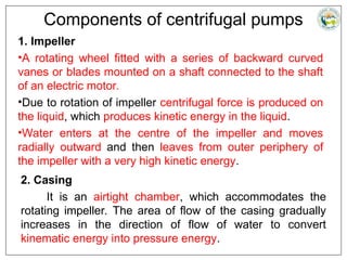
1. Impeller
•A rotating wheel fitted with a series of backward curved
vanes or blades mounted on a shaft connected to the shaft
of an electric motor.
•Due to rotation of impeller centrifugal force is produced on
the liquid, which produces kinetic energy in the liquid.
•Water enters at the centre of the impeller and moves
radially outward and then leaves from outer periphery of
the impeller with a very high kinetic energy.
2. Casing
It is an airtight chamber, which accommodates the
rotating impeller. The area of flow of the casing gradually
increases in the direction of flow of water to convert
kinematic energy into pressure energy.
28.
Components of centrifugalpumps
3. Suction pipe
It is the pipe through which water is lifted from the sump
to the pump level. Thus the pipe has its lower end dipped in
the sump water and the upper end is connected to the eye
or the inlet of the pump. At the lower end, a strainer and a
foot-valve are also fitted.
i. Strainer
It is a screen provided at the foot of the suction pipe, it
would not allow entrance of the solid matters into the
suction pipe which otherwise may damage the pump.
29.
ii. Foot valve
•Itis a one direction valve provided at the foot of the
suction pipe. It permits flow only in one direction i.e.
towards the pump.
•Foot valve facilitates to hold the primed water in the
suction pipe and casing before starting the pump.
•Priming is the process of filling of water in centrifugal
pump from foot valve to delivery valve including casing
before starting the pump.
30.
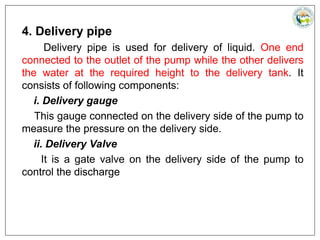
4. Delivery pipe
Deliverypipe is used for delivery of liquid. One end
connected to the outlet of the pump while the other delivers
the water at the required height to the delivery tank. It
consists of following components:
i. Delivery gauge
This gauge connected on the delivery side of the pump to
measure the pressure on the delivery side.
ii. Delivery Valve
It is a gate valve on the delivery side of the pump to
control the discharge
31.
5. Shaft
It isa rotating rod supported by the bearings. It transmits
mechanical energy from the motor to the impeller.
6. Air Relieve Valve
These are the valves used to remove air from casing
while priming.
32.
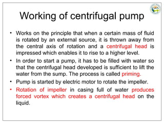
Working of centrifugalpump
• Works on the principle that when a certain mass of fluid
is rotated by an external source, it is thrown away from
the central axis of rotation and a centrifugal head is
impressed which enables it to rise to a higher level.
• In order to start a pump, it has to be filled with water so
that the centrifugal head developed is sufficient to lift the
water from the sump. The process is called priming.
• Pump is started by electric motor to rotate the impeller.
• Rotation of impeller in casing full of water produces
forced vortex which creates a centrifugal head on the
liquid.
33.
Working of centrifugalpump
• The delivery valve is opened as the centrifugal head is
impressed.
• This results in the flow of liquid in an outward radial
direction with high velocity and pressure enabling the
liquid to enter the delivery pipe.
• Partial vacuum is created at the centre of the impeller
which makes the sump water at atmospheric pressure to
rush through the pipe.
• Delivery of water from sump to delivery pipe continues
so long as the pump is on.
34.
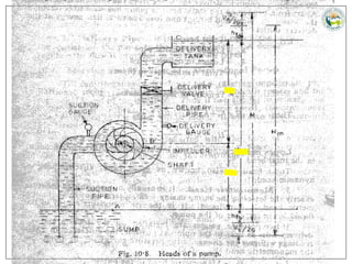
Heads of aPump
1. Static Head
It is the vertical distance between water levels in the
sump and the reservoir.
Let Hst = Static head on the pump
hs = Height of the centre line of pump above the sump
level (Suction head)
hd = Height of the liquid level in the tank above the
centre line of pump (Delivery head)
Then, Hst = hs + hd
36.
Heads of aPump
2. Total Head
It is the total head which has to be developed by a pump to
deliver the water form the sump into the tank. Apart from
producing the static head, a pump has also to overcome the
losses in pipes and fittings and loss due to kinetic energy at
the delivery outlet.
Let H = Total head
hfs = Losses in suction pip
hfd = Losses in delivery pipe
hf = Total friction loss in pipe = hfs + hfd
Vd = Velocity of liquid in delivery pipe.
Then H = hs+ hd + hfs + hfd + Vd
2
/(2g)
Losses in the casing and the impeller are not taken into
account in the total head.
37.
Heads of aPump
3. Manometric Head
It is usually not possible to measure exactly the losses in
the pump casing. So, a term known as manometric head
is introduced. It is the rise in pressure energy of the liquid
in the impeller of the pump.
If two pressure gauges are installed on the suction and the
delivery sides as near to the pump as possible, the
difference in their reading will give the change in the
pressure energy in the pump or the manometric head.
Hm = Manometric head of the pump
Hms = Reading of the pressure gauge on the suction side
Hmd = Reading of the pressure gauge on the delivery side.
Then Hm = Hmd - Hms
38.
Losses and Efficiencies
1.Hydraulic Efficiency
Hydraulic losses are the losses the occur between the
suction and the delivery ends of a pump.
Hydraulic efficiency varies from 0.6 to 0.9.
2. Manometric Efficiency
Manometric efficiency is defined as the hydraulic
efficiency of an ideal pump.
39.
Losses and Efficiencies
3.Volumetric Efficiency
The pressure at the outlet of the impeller is higher than at
the inlet. Thus there is always a tendency on the part of
water to slip back or leak back through the clearance
between the impeller and the casing. There can also be
some leakage from the seals. These are called volumetric
losses.
Volumetric efficiency is the ratio of the actual discharge to
the total discharge.
Q = Amount of discharge
Let ∆Q = Amount of leakage.
ηv = Q / (Q+ ∆Q)
Its value lies between 0.97 and 0.98.
40.
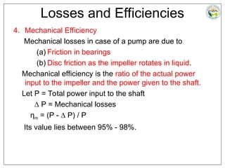
Losses and Efficiencies
4.Mechanical Efficiency
Mechanical losses in case of a pump are due to
(a) Friction in bearings
(b) Disc friction as the impeller rotates in liquid.
Mechanical efficiency is the ratio of the actual power
input to the impeller and the power given to the shaft.
Let P = Total power input to the shaft
∆ P = Mechanical losses
ηm = (P - ∆ P) / P
Its value lies between 95% - 98%.
41.
Losses and Efficiencies
5.Overall Efficiency
It is the ratio of the total head developed by a pump to
the total power input to the shaft.
ηo = (ρQgH) / P
Range of overall efficiency is between 0.71 to 0.86.
42.
Problem: A centrifugalpumps delivers 50 liters of water per
second to a height of 15m through a 20 m long pipe.
Diameter of the pipe is 14 cm. Overall efficiency is 72 %,
and the coefficient of friction 0.015. Determine the power
needed to drive the pump.
Solution:
Hs = 15m
Q=0.05 m3
/s
I = 20 m
f = 0.015
d = 0.14 m
ηo = 72%
We have,
ηo = (ρQgH) / P
H = Hs+ Hf + Vd2
/(2g)
43.
For which Vdis given by,
Q = π/4 d2
Vd
0.05=π/4(0.14)2
Vd
Vd = 3.25 m/s
And hf = (4flVd
2
) / (2gd)
hf = (4x0.015x20x3.252
)/(2x9.81x0.14)
hf = 4.61 m
H=15+4.61+ 3.252
/(2x9.81)= 20.15m
Power to drive pump can be calculated as follows:
ηo = (ρQgH) / P
0.72 = (1000x0.05x9.81x20.15) / P
Or P = 13726 W = 13.726 k W.
44.
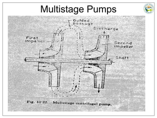
Multistage Pumps
To developa high head, the tangential speed μo has to
be increased. However an increase in the speed also
increases the stresses in the impeller material. This
implies that centrifugal pump with one impeller cannot be
used to raise high heads.
More than one pump is needed to develop a high head.
The discharge of one pump is delivered to the next to
further augment the head.
However, a better way is to mount two or more impellers
on the same shaft and enclose them in the same
cashing. All the impellers are put in series so that the
water coming out of one impeller is directed to the next
impeller and so on (Fig.10.22).
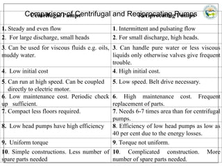
Comparison of Centrifugaland Reciprocating Pumps
Centrifugal Pumps Reciprocating Pumps
1. Steady and even flow 1. Intermittent and pulsating flow
2. For large discharge, small heads 2. For small discharge, high heads.
3. Can be used for viscous fluids e.g. oils,
muddy water.
3. Can handle pure water or less viscous
liquids only otherwise valves give frequent
trouble.
4. Low initial cost 4. High initial cost.
5. Can run at high speed. Can be coupled
directly to electric motor.
5. Low speed. Belt drive necessary.
6. Low maintenance cost. Periodic check
up sufficient.
6. High maintenance cost. Frequent
replacement of parts.
7. Compact less floors required. 7. Needs 6-7 times area than for centrifugal
pumps.
8. Low head pumps have high efficiency 8. Efficiency of low head pumps as low as
40 per cent due to the energy losses.
9. Uniform torque 9. Torque not uniform.
10. Simple constructions. Less number of
spare parts needed
10. Complicated construction. More
number of spare parts needed.


![SBP- Centrifugal and recoprocating pump [Compatibility Mode].pdf](https://cdn.slidesharecdn.com/ss_thumbnails/sbp-centrifugalandrecoprocatingpumpcompatibilitymode-241227102119-6ae861f2-thumbnail.jpg?width=640&height=640&fit=bounds)


