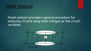
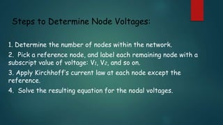
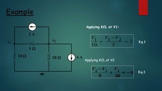
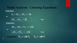
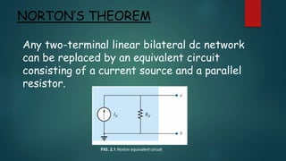
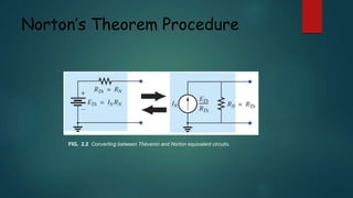
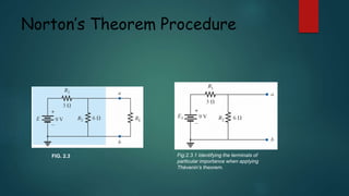
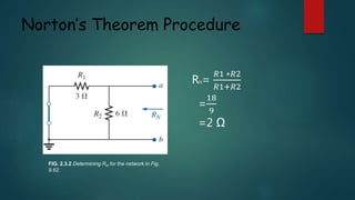
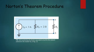
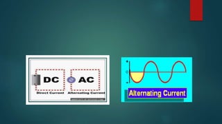
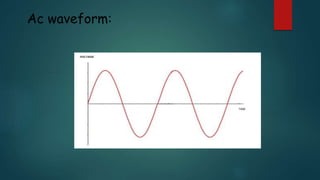
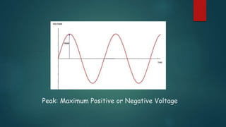
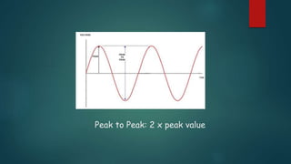
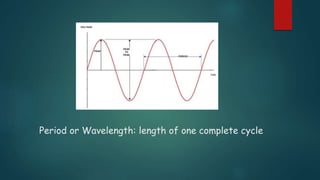
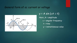
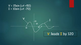
Welcome to the
Presentation
presentation topic :
>>Node voltage
>>Norton Theorem
>>Ac Fundamental
Group members
Name ID
Bayezid Bostami 151-15-4681
Manisha Barman 151-15-4682
Ashaduzzaman kanon 131-15-2392
>>Agenda:
>>procedure of node voltage and explanation .
>>procedure of Norton theorem and explanation .
>>Ac Fundamental Basic.
Nodal Analysis
Nodal analysis provides a general procedure for
analyzing circuits using node voltages as the circuit
variables.
reference node
v1
v2 v3
R2
R1
R3
R4
I

Steps to Determine Node Voltages:
1. Determine the number of nodes within the network.
2. Pick a reference node, and label each remaining node with a
subscript value of voltage: V1, V2, and so on.
3. Apply Kirchhoff’s current law at each node except the
reference.
4. Solve the resulting equation for the nodal voltages.
Example
Applying KCL at V1:
Applying KCL at V2
v1
v2
10 
5 
20  4 A
2 A
 2
5
21
10
1 


VVV
Eq 1
6
205
212 
 VVV
Eq 2
Nodal Analysis: Clearing Equations
From Eq 1:
V1 + 2V1 – 2V2 = 20
or
3V1 – 2V2 = 20
From Eq 2:
4V2 – 4V1 + V2 = -120
or
-4V1 + 5V2 = -120
Eq 3
Eq 4
Solution: V1 = -20 V, V2 = -40 V
9
Edward Lawry Norton was an
accomplished Bell Labs engineer and
scientist famous for developing the
concept of the Norton equivalent circuit.
NORTON’S THEOREM
Any two-terminal linear bilateral dc network
can be replaced by an equivalent circuit
consisting of a current source and a parallel
resistor.
FIG. 2.1 Norton equivalent circuit.
Norton’s Theorem Procedure
FIG. 2.2 Converting between Thévenin and Norton equivalent circuits.
Norton’s Theorem Procedure
FIG. 2.3 Fig:2.3.1 Identifying the terminals of
particular importance when applying
Thévenin’s theorem.
Norton’s Theorem Procedure
FIG. 2.3.2 Determining RN for the network in Fig.
9.62.
RN=
𝑅1 ∗𝑅2
𝑅1+𝑅2
=
18
9
=2 Ω
Norton’s Theorem Procedure
FIG. 2.3.3 Determining IN for the
network in Fig. 2.3.2
Norton’s Theorem Procedure
FIG. 2.4 Substituting the Norton equivalent circuit for the network
external to the resistor RL in Fig. 2.3.
War of current
Ac waveform:
Peak: Maximum Positive or Negative Voltage
Peak to Peak: 2 x peak value
Period or Wavelength: length of one complete cycle
General form of ac current or voltage
y = A sin (t  )
Here ,A = amplitude
 = angular frequency
t = time
y = instantaneous value
V = 15sin (t +50)
I = 10sin (t -70)
50
15
70
10
V
I
V leads I by 120
Advantage :
>>AC current can be transformed and DC current cannot
be transformed.
>>It can be controlled by a wide range of components e.g.
resistors ,capacitors and inductors.
>>This allows high-voltage electrical power to be
distributed with smaller wires and lower amperage.
Acknowledgement :
S.M.Safayet Ullah
Lecturer
Department of Natural Sciences
Daffodil International University
References:
1.Introductory Circuit Analysis by Robert L. Boylesterd
2.Fundemantal of Electric circuit by Alexander & sadiku.
3. en.wikipedia.org/wiki/Edward_Lawry_Norton.
Thank you

node voltage,thevenin's theorem, AC Fundamentals