Electrical and Electronics Engineering
•
2 likes•74 views

Electrical Engineering is the Branch of Engineering. Electrical Engineering field requires an understanding of core areas including Thermal and Hydraulics Prime Movers, Analog Electronic Circuits, Network Analysis and Synthesis, DC Machines and Transformers, Digital Electronic Circuits, Fundamentals of Power Electronics, Control System Engineering, Engineering Electromagnetics, Microprocessor and Microcontroller. Ekeeda offers Online Mechanical Engineering Courses for all the Subjects as per the Syllabus.

More Related Content
What's hot
What's hot (20)
Similar to Electrical and Electronics Engineering
Similar to Electrical and Electronics Engineering (20)
More from Ekeeda
More from Ekeeda (20)
Recently uploaded
Recently uploaded (20)
Electrical and Electronics Engineering
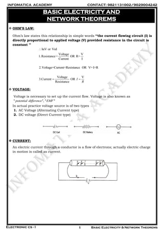
- 1. INFOMATICA ACADEMY CONTACT: 9821131002/9029004242 Electronic cs - I Basic Electricity & Network Theorems1 BASIC ELECTRICITY AND NETWORK THEOREMS OHM’S LAW: Ohm’s law states this relationship in simple words ‘‘the current flowing circuit (I) is directly proportional to applied voltage (V) provided resistance in the circuit is constant ’’ IαV or VαI Voltage V 1.Resistance= OR R= Current I 2.Voltage=Current×Resistance OR V=I×R Voltage V 3.Current OR Resistance I R VOLTAGE: Voltage is necessary to set up the current flow. Voltage is also known as '' '', '' ''potential difference EMF In actual practice voltage source is of two types 1. AC Voltage (Alternating Current type) 2. DC voltage (Direct Current type) CURRENT: An electric current through a conductor is a flow of electrons; actually electric charge in motion is called as current.
- 2. INFOMATICA ACADEMY CONTACT: 9821131002/9029004242 Electronic cs - I Basic Electricity & Network Theorems2 Conventional Current: The electron flow is always from-Ve terminal to +Ve terminal of the battery but theoretically it is assumed to be from positive to negative, because as a convention, electric current direction a conventional current from positive to negative. Electron Flow & conventional current SOURCES OF ELECTRICITY: i) AC Source and ii) DC Source i) AC Source: a) Signal generator: If can generate AC supply with variable voltage and variable frequency, sometimes, they are capable of generating different AC signal with different waveforms like square wave, triangular wave, sawtooth etc.
- 3. INFOMATICA ACADEMY CONTACT: 9821131002/9029004242 Electronic cs - I Basic Electricity & Network Theorems3 b) Alternator: It is a sort of generator can generate AC supply converting mechanical energy into electrical energy. E.g. in auditorium when MSEB fails they start generators or while in festivals or Circus owner they use their self-generators. DC SOURCES: We get AC supply from main electric power station but most of the electronic circuits work on DC supply, user has to take DC supply from the following sources i) Batteries ii) DC generators iii) Rectifiers iv) solar cell The battery is a very common DC source because of its high current capacity and recharging facility. It can be recharged for many times; now a day in automobile applications it is continuously charged by electronic circuits when engine starts. A battery is a unit in which no. of cell are arranged in series and parallel arrangement. The DC generator is a dynamic engine it generates DC energy by means of rotating shaft it generates electrical energy by converting mechanical energy. A rectifier is an electronic instrument which converts mains AC supply into DC there is no rotating part. IDEAL AND PRACTICAL VOLTAGE SOURCE: Ideal voltage source is not possible; the source cannot maintain source voltage at its terminals it would mean that it could supply an infinite power to a load even if the circuit is a short circuit. A practical voltage source is the true source it is a source with small internal impedance as indicated by fig. There I-V characteristics show that as load current increases its terminal voltage decreases due to drop across its internal impedance.
- 4. INFOMATICA ACADEMY CONTACT: 9821131002/9029004242 Electronic cs - I Basic Electricity & Network Theorems4 IDEAL AND PRACTICAL CURRENT SOURCE: A current source can be a source, which can deliver constant current even if load varies from low to high value. It is a quite similar concept of ideal current source, where it supplies constant current (I) even current through load varies. It means that even if the circuit is an open circuit practically current flow is not possible. On the other hand a practical current source is represented by a current source with internal impedance in parallel with source. It can be stated that a good current source has high internal impedance so that very small current is passed through it and almost constant current flows through the load. As shown in the fig LZ=Ziparallel Z L LZ=Z when Z =0 or Zi= Comparison: Voltage source Current source It is voltage with minimum internal impedance. It is voltage with maximum internal impedance. It is a voltage source in series with Zi It is a voltage source in parallel with Zi It works when ZL>>Zi It works when Zi>>ZL
- 5. INFOMATICA ACADEMY CONTACT: 9821131002/9029004242 Electronic cs - I Basic Electricity & Network Theorems5 IMPORTANT FORMULAE 1. Rt=R1+R2+R3+……….Series circuit 2. 1 2 3 1 1 1 1 TR R R R ……..Parallel circuit 3. When R1 and R2 are in series across a supply V then voltage across R2 By voltage divider formula 2 2 1 2 R R X V V R R 4. When R1 and R2 are in parallel then the current through R2 by current divider formula 1 2 2 1 1 2 1 2 T TR X I R X I I I R R R R POWER: Power is defined, as ‘‘it is the rate of doing electric work ‘’. Now we can make one more relation by substituting (I=V/R) in equation (1) 2 2 2 ( / ) ...........(3) Formulae: (1) (2) (3) P V V R V P R V P V I P I R P R 2 / But / / / Substituting these two / ............(1) (Watts Volts Amp) Substituting in equation (1) ( ) .............(2) P W t V W Q W V Q and I Q t Q I V Q P V I Q I P V I V IR P IR I P I R
- 6. INFOMATICA ACADEMY CONTACT: 9821131002/9029004242 Electronic cs - I Basic Electricity & Network Theorems6 KIRCHHOFF’S LAWS: (1) Kirchhoff’s current law (KCL): It states that ‘‘The algebraic sum of currents at any junction or node is always zero’’. Where currents coming towards node are considered with positive sign and currents leaving the node are considered with negative sign. As shown in fig. the equation for node will be 1 2 3 4 0I I I I (2) Kirchhoff’s voltage law (KVL): It states that ‘‘The algebraic sum of voltages around any closed loop is always zero.’’ Here loop means a closed circuit path. Kirchhoff’s equation can be written as 1 2 3 1 2 3.V V V V or V V V V SUPERPOSITION THEOREM: Statement: ‘‘In a network containing two or more sources, the current or voltage for any component is the algebraic of the results produced by each source acting individual source’’. Example 1: Find the P.D. between point A and B
- 7. INFOMATICA ACADEMY CONTACT: 9821131002/9029004242 Electronic cs - I Basic Electricity & Network Theorems7 Solution: Step-I Make V2 short and find VAB across R2 say (V1) By Voltage divider formula 2 1 1 2 a R V V R R 6 24 16 9 a K V V K Step-II Now make V1 short and find VAB across R1 say (V2) 1 2 1 2 b R V V R R 3 9 3 9 bV V Example 2: Find current through 3R if 3 1R K Step-I Make 2V short & find voltage across 2R (say aV ) 12 30 20 18 a x V V Step- II Make 1V short and find voltage across 1R (Say bV ) 2 1 1 2 30 6 18 b V x R x V R R 10 V Step-III Apply Superposition AB a bV V V = 20+10 =30V The current through 3 3 3 3 30 30 10 30 1 10 ABV R mA R Drawback of superposition theorem: it is suitable only when the network contains linear components.
- 8. INFOMATICA ACADEMY CONTACT: 9821131002/9029004242 Electronic cs - I Basic Electricity & Network Theorems8 THEVENIN’S THEOREM: Statement: Any linear active, resistive complex network containing one or more sources can be replaced by an equivalent voltage source (Veq) and a series equivalent resistance (Req). Where (Veq) or ( THV ) = The venin’s equivalent voltage source And (Re ) ( )THq or R = Thevenin’s Equivalent resistance NORTON’S THEOREM: Statement: Any linear active, resistive complex network containing one or more sources can be replaced by an equivalent current source (Ieq) and a parallel equivalent resistance (Req). Where ( ) ( )NIeq or I = Norton’s equivalent current source And (Re ) ( )Nq or R = Norton’s Equivalent resistance
- 9. INFOMATICA ACADEMY CONTACT: 9821131002/9029004242 Electronic cs - I Basic Electricity & Network Theorems9 COMPARISON OF THEVENIN’S WITH NORTON’S THEOREM: Thevenin’s Theorem Norton’s Theorem 1. It is used when a complex network contains one or many voltage sources. 1. It is used when a complex network contains one or many current sources 2. Mostly used in analysis voltage. 2. Mostly used in analysis of current 3. It has a single equivalent voltage source (Veq) when terminals are open circuited. 3. It has a single equivalent current source (Ieq) when terminals are short circuited. 4. The Thevenins equivalent resistace (Req) is in series with Veq. 4. Req is in parallel with Ieq. 5. Thevenin’s Equivalent circuit 5. Norton’s Equivalent circuit Example 1: Draw Thevenin’s equivalent circuit and find voltage across ‘RL’. Step (I) Step (II) Make terminal AB open and find Veq Make terminal AB open and find Veq 2 2 2 2 1 2 1 2 R eq R eq VxR VxR V V V V R R R R 6 12 6 10 4 6.66 18 9 x x V V (Note that R3 is open hence VR2 is Veq)
- 10. INFOMATICA ACADEMY CONTACT: 9821131002/9029004242 Electronic cs - I Basic Electricity & Network Theorems10 Step (II) Find Req by making source short 1 2 1 2 3 1 2 1 2 Re Re R x R R x R q q R R R R R 6 12 6 3 4 3 5 18 9 x x Step (III) Step (III) Draw Thevenine’s equivalent circuit Draw Thevenine’s equivalent circuit & find VL & find VL 2 2 Re Re 4 6 6.6 3 2.4 2.4975 10 8 L L R R L L Veq x R Veq x R V V q R q R x x V V Example 2: Find Current through the load and voltage across the load by Norton’s theorem in the given circuit. Solution: Step (I) Make output terminals short and find short find short circuit current Ieq. Note: that 20 Ω resistance becomes short or 0 Ω J
- 11. INFOMATICA ACADEMY CONTACT: 9821131002/9029004242 Electronic cs - I Basic Electricity & Network Theorems11 Step (II) Make voltage source short and find Req. Step (III) Draw Norton’s equivalent circuit and find IL and VL. It can be verified by Thevenin’s equivalent circuit. Step (I) Find Veq by making AB open Step (II) Find Req or use Req from Norton’s method and find VL by voltage divider formula.
- 12. INFOMATICA ACADEMY CONTACT: 9821131002/9029004242 Electronic cs - I Basic Electricity & Network Theorems12 Example 3: Find VL and IL by Norton’s & Thevenin’s Theorem. Solution: Applying Norton’s Theorem Step (I) Make the output terminals short and find short circuit current Ieq. Step (II) Make source voltage short and find Req. Step (III) Draw Norton’s equivalent circuit and find IL and VL It can be verified by Thevenin’s equivalent circuit. Step (I) Find Veq by making AB open
- 13. INFOMATICA ACADEMY CONTACT: 9821131002/9029004242 Electronic cs - I Basic Electricity & Network Theorems13 Example 4: Find VL and IL by using both Norton’s & Thevenin’s Theorems. Solution: (A) Applying Norton’s Theorem Step (I) Make the output terminals short and find short-circuit current Ieq. Step (II) Make the source voltage short and find Req. Step (III) Draw Norton’s equivalent circuit and find IL It can be verified by Thevenin’s equivalent circuit.
- 14. INFOMATICA ACADEMY CONTACT: 9821131002/9029004242 Electronic cs - I Basic Electricity & Network Theorems14 (B) Applying Thevenin’s Theorem Step (I) Find Veq by making AB open. Veq is nothing but voltage across R2 because AB is open. MAXIMUM POWER TRANSFER THEOREM: ‘’The maximum power transfer takes place when the load resistance 1( )R is equal to the to the equivalent source resistance (Req)’’. Comparison Of Electric And Magnetic Field: Electric circuit Magnetic circuit 1. Electric field results in electron flow 1. Magnetic system results in flux. 2. Flow of electron is current. 2. Flow of flux. 3. The cause of current is E.M.F. (Voltage) 3. The cause of flux is M.M.F Magneto Motive Force. 4. Opposition to the flow of electron is known as resistance (R) 4. Opposition to the flow is known as reluctance (R) 5. Resistance is given by R=σ1 A where is the conductivity. 5. Reluctance is given by R=1 μ where is the permeability. 6. Conductance = 1 R 6. Permanence= 1 R 7. Ohms law =V I 7. Reluctance R=MMF/ 8. Current in an electric circuit is due to electron flow. 8. Flux in magnetic circuit does not actually flow. 9. Magnetic field is generated when curre3nt flows through a conductor. 9. Electricity can be generated by magnetic field. 10.Energy is required to maintain the current in the 10.Energy is required only to create flux but not no maintain it.
- 15. INFOMATICA ACADEMY CONTACT: 9821131002/9029004242 Electronic cs - I Basic Electricity & Network Theorems15 ELECTROMAGNETISM: Magnetic field is always produced around the conductor, when electric current flows through it. This phenomenon can be observed by performing simple experiment as shown in fig…. Shown that when current flows through the conductor iron filings are aligned in concentric rings around the conductor; this shows that magnetic field is developed in circular orbits around the conductor. Another important conclusion is, iron filings are dense near to the conductor that is magnetic field is strongest neat the conductor and it decreases with increase in distance. Third conclusion is- higher is the current flow higher is the magnetic field. Magnetic force of lines is known as ‘‘ ( )’’magnetic flux and the number of magnetic lines of force that pass through the unit area of a section perpendicular to the direction of the magnetic flux is known as‘‘ ’’.fluxdensity ELECTROMAGNETIC INDUCTION: Electrons in motion (current) produce a magnetic field, similarly when magnetic flux moves, it forces free electrons in conductor to move, which produce an electric current. Shows the conductor AB is placed at right angles to the flux produced by the magnet. When magnet is moved up and down, the conductor cuts the lines of magnetic flux. Therefore whenever the conductor cuts flux current is produced in the conductor. This current is observed in micrometer as shown. When magnet is moved downward, current flows from A to B and when it moves upward, current flows in opposite direction. If you move conductor AB instead of magnet then also induction can be observed because the conductor cuts magnetic flux. Hence whenever either flux is in motion or conductor is in motion electricity is produced in the conductor by induction. Same principle is used in an electric generator.
- 16. INFOMATICA ACADEMY CONTACT: 9821131002/9029004242 Electronic cs - I Basic Electricity & Network Theorems16 INDUCTANCE: It is the ability of conductor induced voltage, when current through it varies. Induced voltage is the result of flux cutting across a conductor because when ac current flows through it magnetic flux varies its strength and the direction, which is equivalent to motion of magnetic flux. FARADAY’S LAW: When a conductor cuts the line of magnetic field (flux) an e.m.f. is generated in the conductor or when magnetic flux is made varying across the conductor an e.m.f. can be generated in the conductor. The voltage induced by induction depends upon the following three factors: 1) Amount of Flux ( ) : Higher is the number of magnetic lines of force (or magnetic flux) higher will be the induced voltage. 2) Number of Turns (N): The more turns in a coil the higher is induced voltage, because induced voltage is the sum of individual voltages generated in each turn of the coil. 3) Faster the rate of cutting flux, higher is the induced voltage. SELF INDUCTANCE AND MUTUAL INDUCTANCE: The ability of a conductor to induce voltage in itself when the current changes through it, is known as its‘‘ Self inductance’’or simply inductance. The notation of inductance is ‘L’ and it is measured in ‘Henry’. This induced voltage has a tendency to oppose change in current. Therefore induced voltage is often called as ‘‘counter emf’’ or ‘‘back emf’’. When current through coil is AC and if voltage is induced in itself it is called as its ‘self-inductance’. But when AC current flows through one coil and voltage is induced in other coil placed near to it then it is known as ‘mutual inductance’.