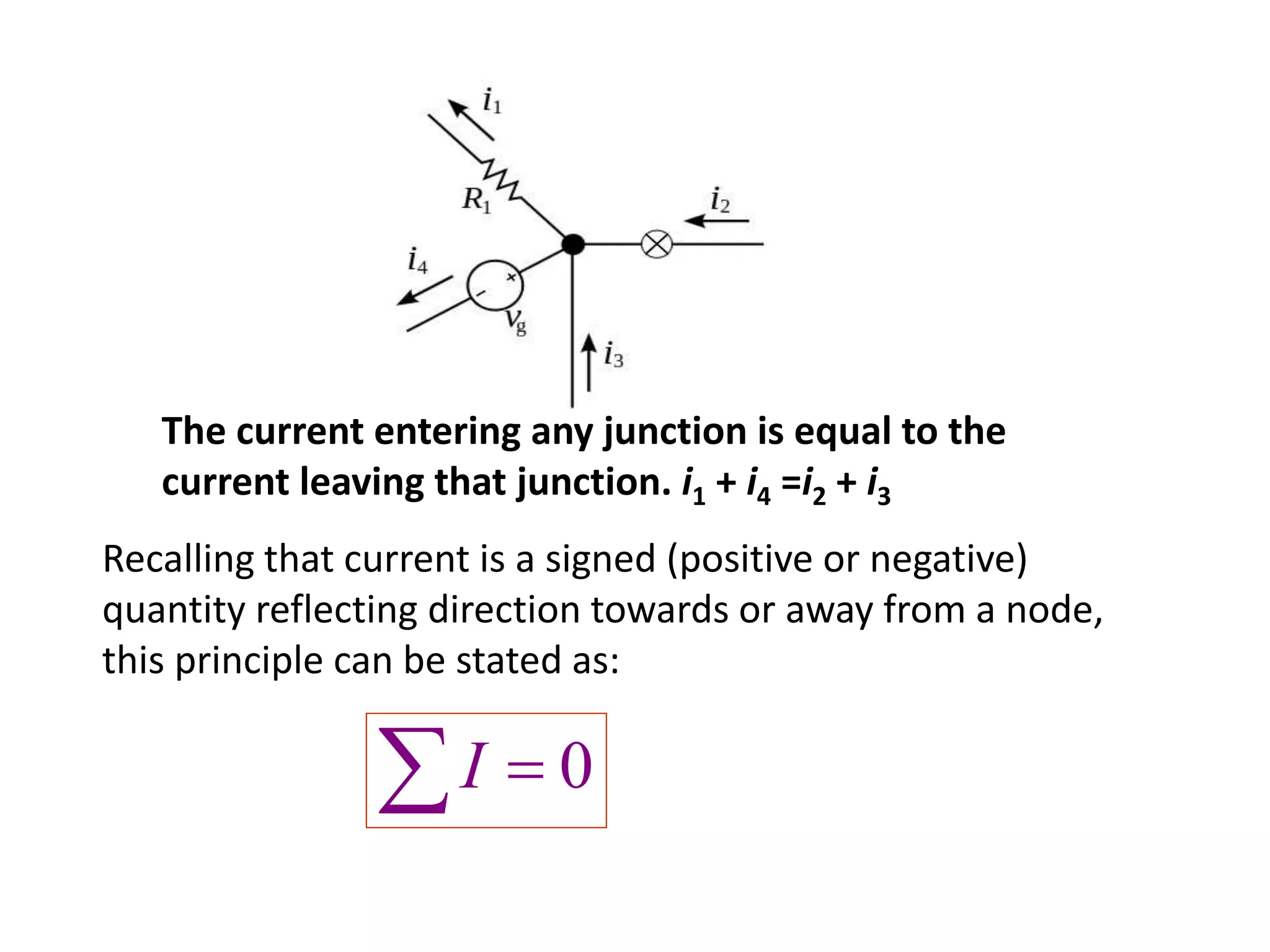
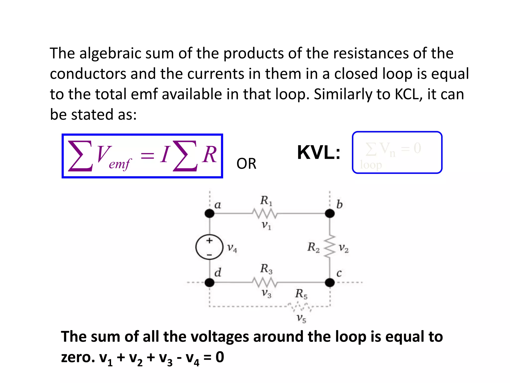
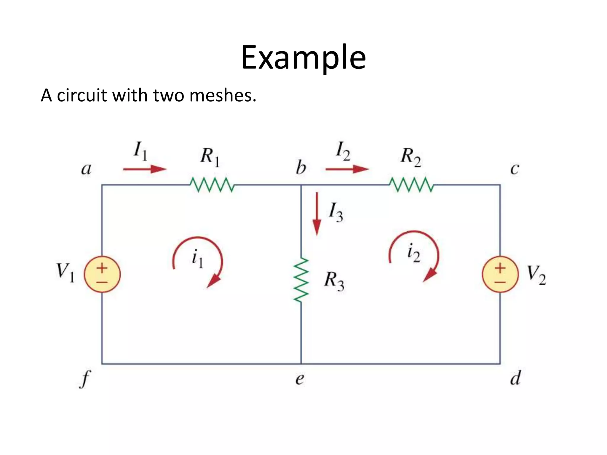
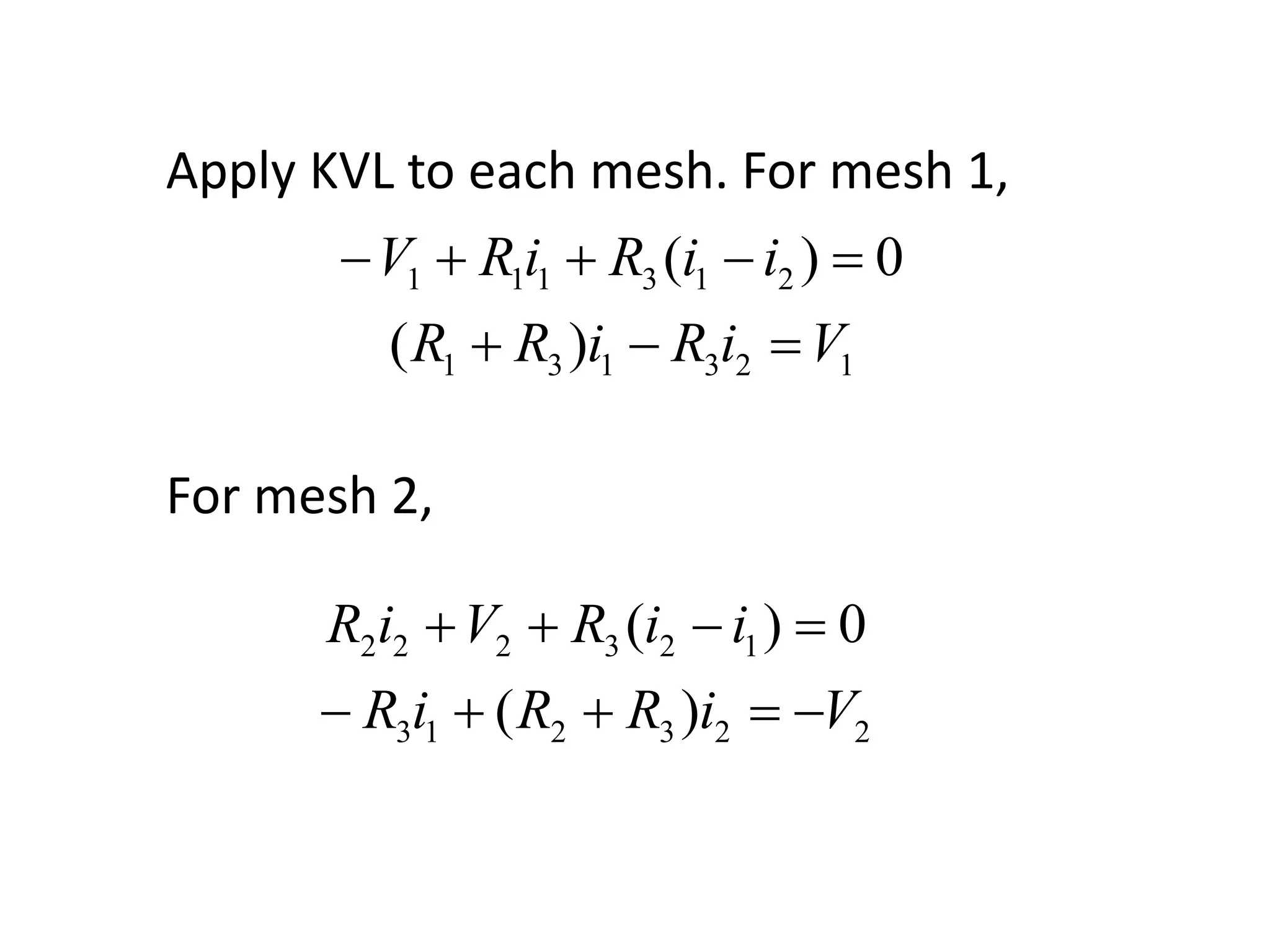
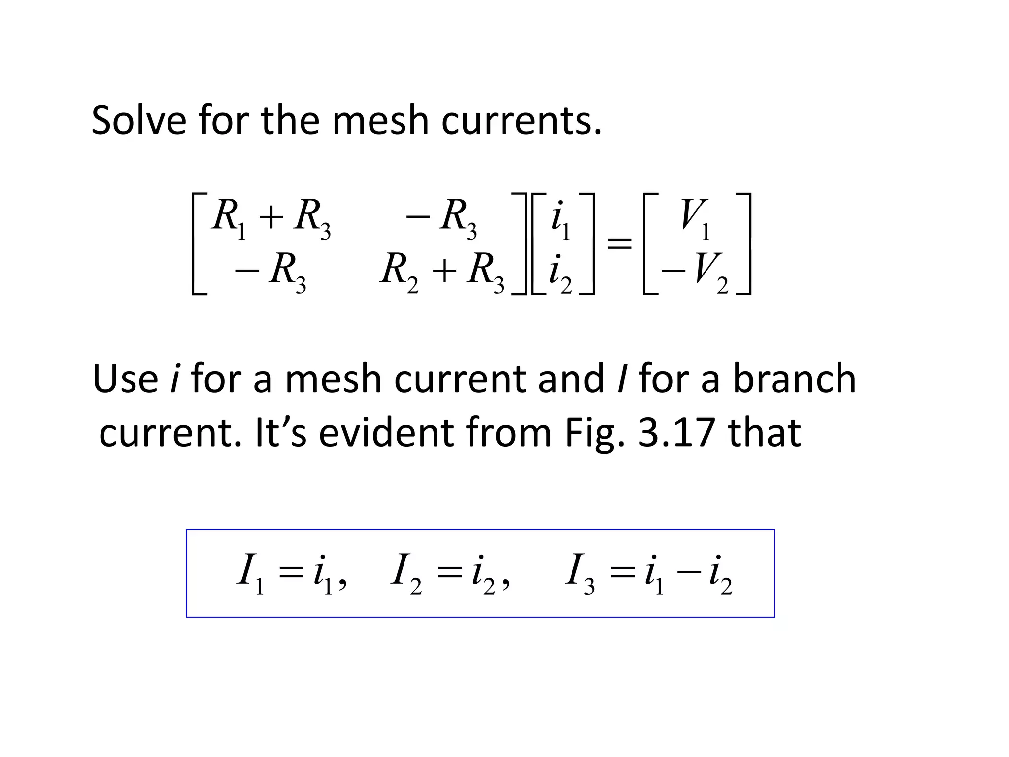
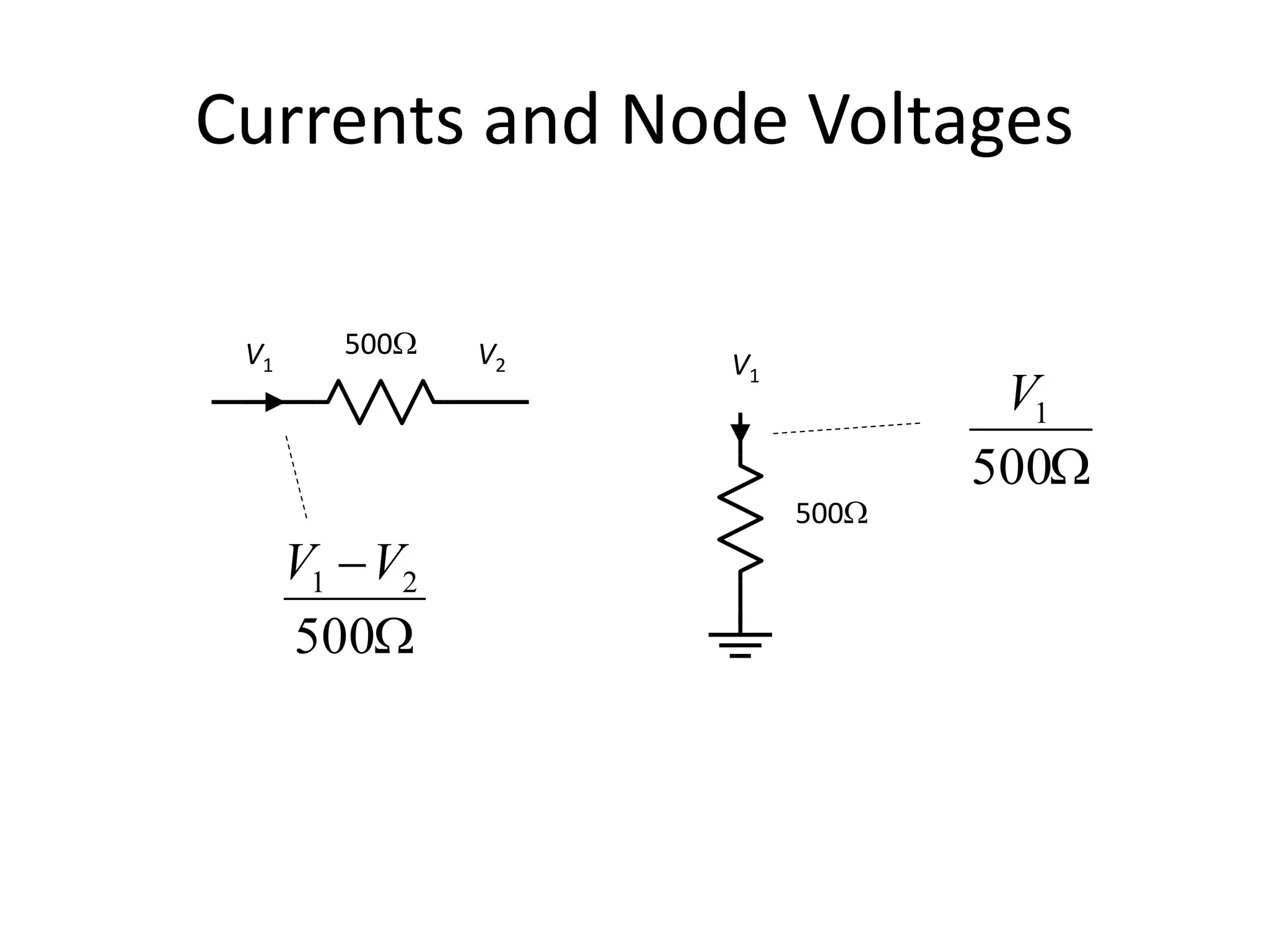
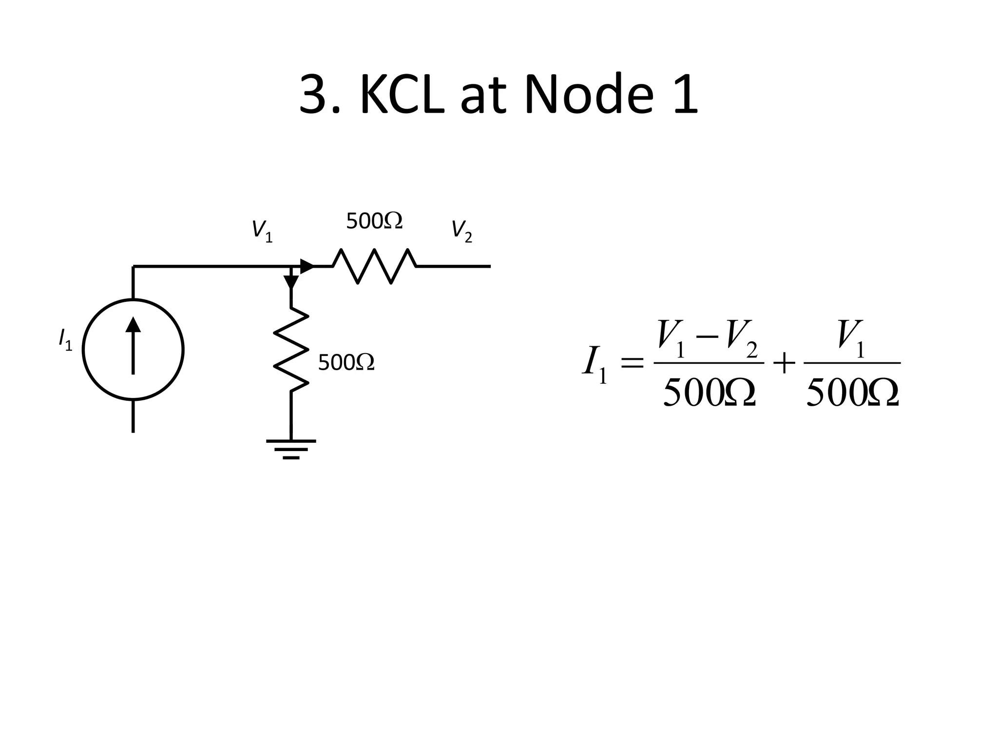
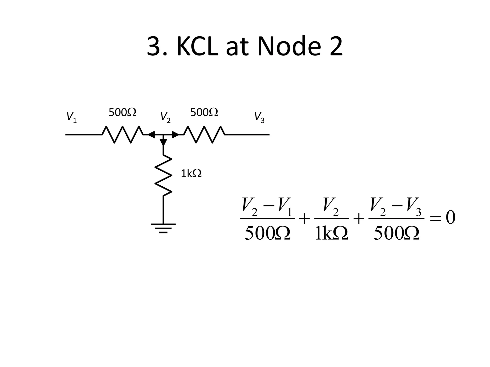
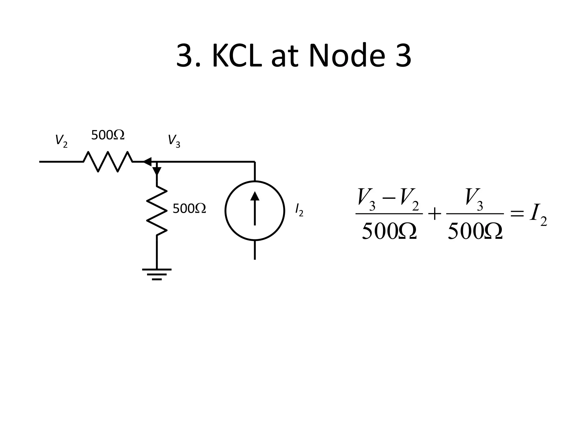
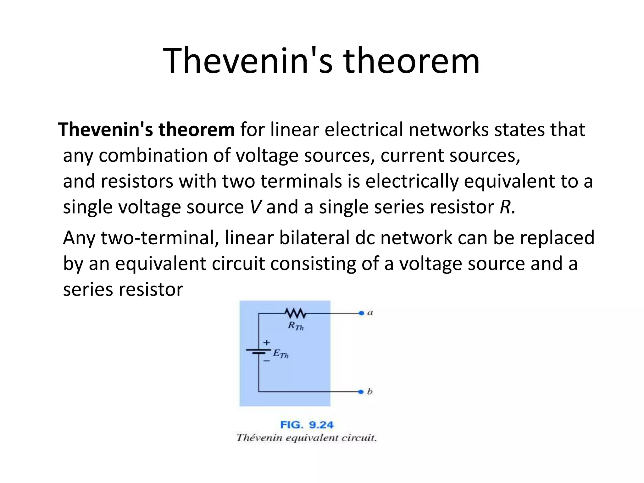
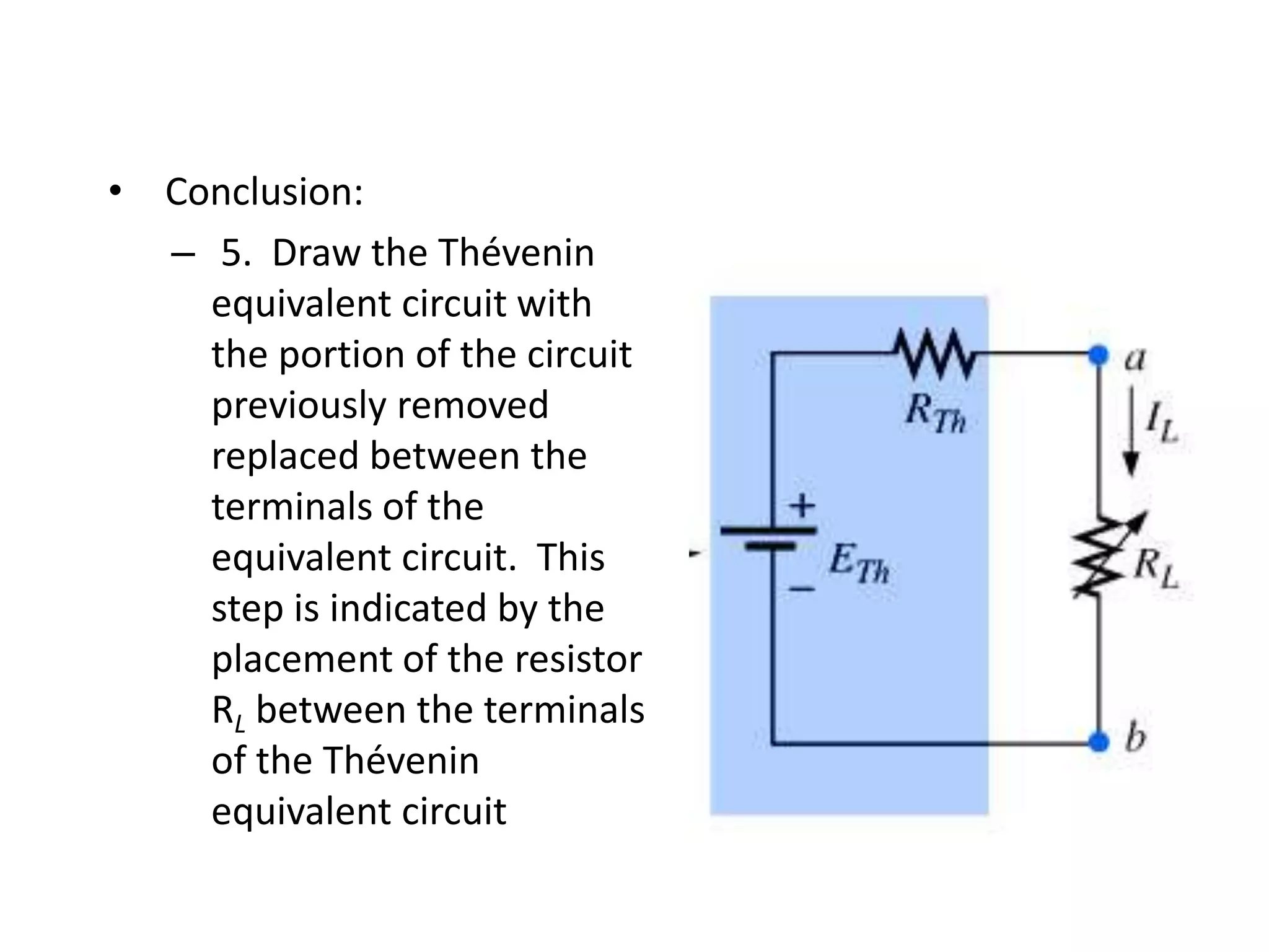
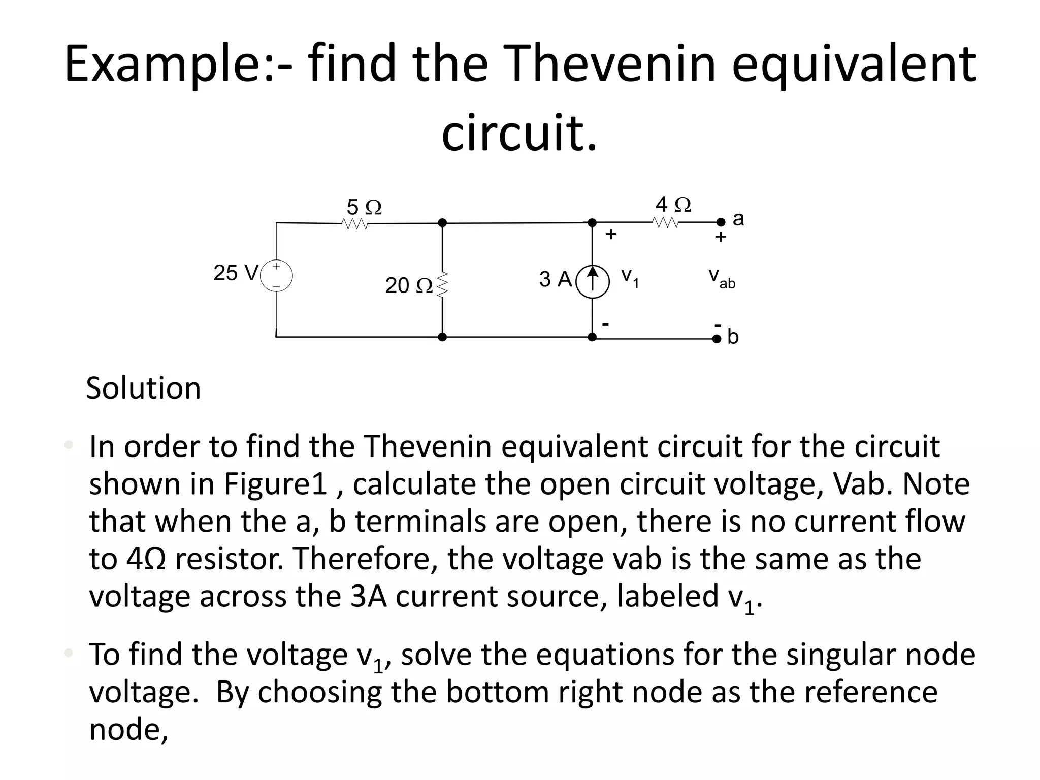
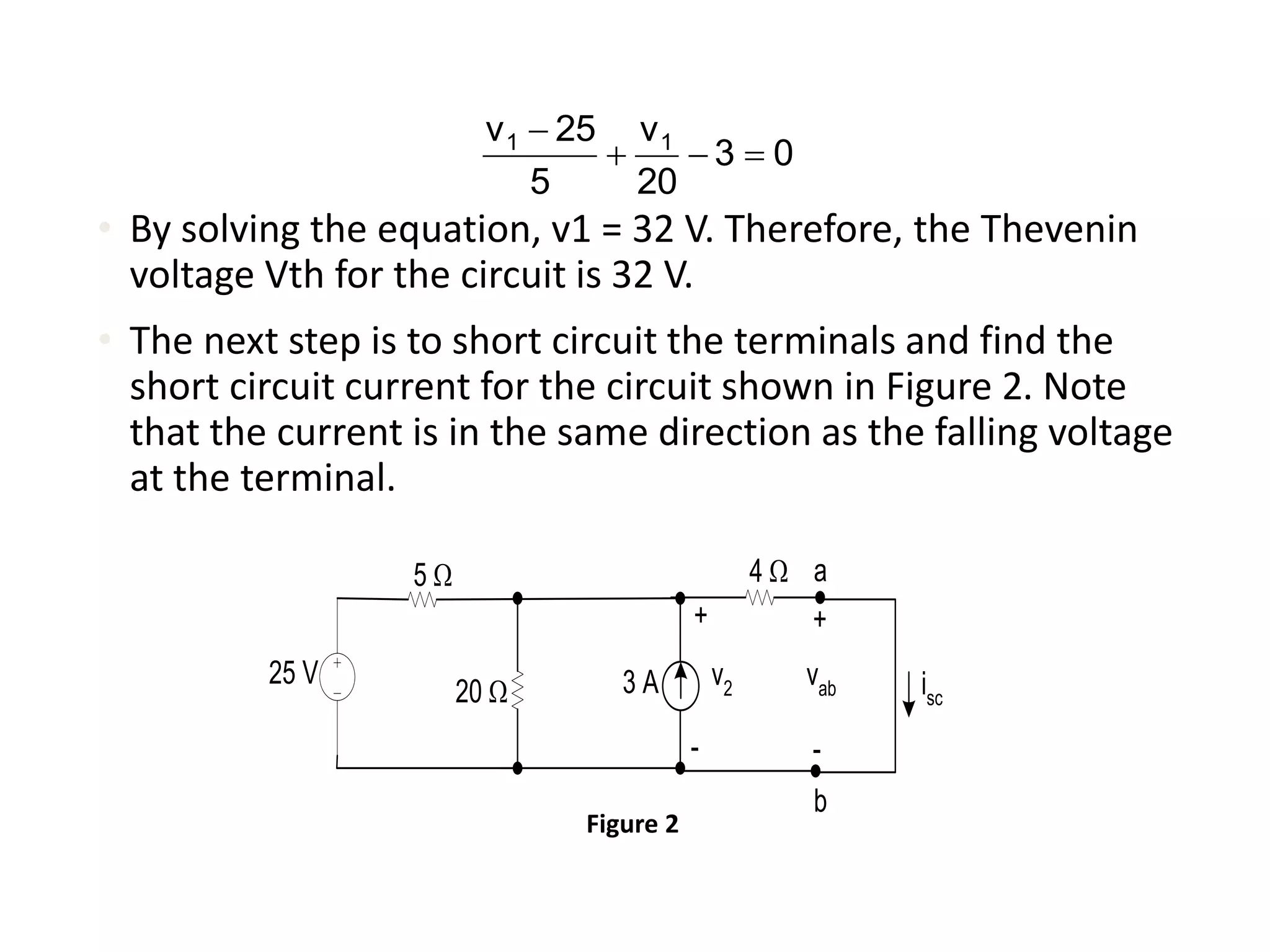
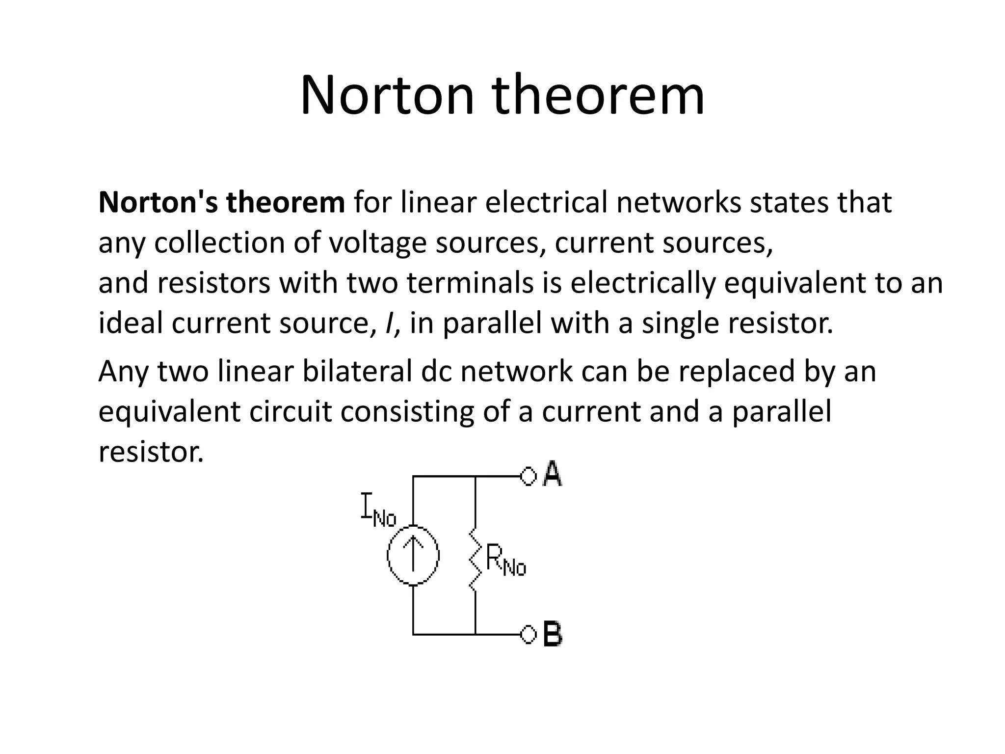
SlideShare a Scribd company logo
1 of 49
Kirchhoff's Laws
Kirchhoff's circuit laws are two equalities that deal with
the conservation of charge and energy in electrical circuits.
There basically two Kirchhoff's law :-
1. Kirchhoff's current law (KCL) – Based on principle of
conservation of electric charge.
2. Kirchhoff's voltage law (KVL) - Based on principle of
conservation of energy.
Kirchhoff's current law (KCL)
This law is also called Kirchhoff's first law, Kirchhoff's point
rule, Kirchhoff's junction rule (or nodal rule), and Kirchhoff's
first rule.
The principle of conservation of electric charge implies that:
At any node (junction) in an electrical circuit, the sum
of currents flowing into that node is equal to the sum of
currents flowing out of that node, or The algebraic sum of
currents in a network of conductors meeting at a point is zero.
Strictly speaking KCL only applies to circuits with steady
currents (DC).
However, for AC circuits having dimensions much smaller
than a wavelength, KCL is also approximately applicable.
The current entering any junction is equal to the
current leaving that junction. i1 + i4 =i2 + i3
Recalling that current is a signed (positive or negative)
quantity reflecting direction towards or away from a node,
this principle can be stated as:
  0I
Kirchhoff's voltage law (KVL)
This law is also called Kirchhoff's second law, Kirchhoff's loop
(or mesh) rule, and Kirchhoff's second rule.
The principle of conservation of energy implies that
The directed sum of the electrical potential
differences (voltage) around any closed circuit is zero, or
More simply, the sum of the emfs in any closed loop is
equivalent to the sum of the potential drops in that loop
Strictly speaking KVL only applies to circuits with steady
currents (DC).
However, for AC circuits having dimensions much smaller than
a wavelength, KVL is also approximately applicable.
The algebraic sum of the products of the resistances of the
conductors and the currents in them in a closed loop is equal
to the total emf available in that loop. Similarly to KCL, it can
be stated as:
OR  RIVemf
Vn
loop
 0KVL:
The sum of all the voltages around the loop is equal to
zero. v1 + v2 + v3 - v4 = 0
Mesh Analysis
Mesh analysis (or the mesh current method) is a method that
is used to solve planar circuits for the currents (and indirectly
the voltages) at any place in the circuit. Planar circuits are
circuits that can be drawn on a plane surface with
no wires crossing each other.
Mesh analysis works by arbitrarily assigning mesh currents in
the essential meshes. An essential mesh is a loop in the circuit
that does not contain any other loop.
Steps to Determine Mesh Currents:
1. Assign mesh currents i1, i2, .., in to the n meshes.
Current direction need to be same in all meshes
either clockwise or anticlockwise.
2. Apply KVL to each of the n meshes. Use Ohm’s
law to express the voltages in terms of the mesh
currents.
3. Solve the resulting n simultaneous equations to
get the mesh currents
Example
A circuit with two meshes.
Apply KVL to each mesh. For mesh 1,
For mesh 2,
123131
213111
)(
0)(
ViRiRR
iiRiRV


223213
123222
)(
0)(
ViRRiR
iiRViR


Solve for the mesh currents.
Use i for a mesh current and I for a branch
current. It’s evident from Fig. 3.17 that
















2
1
2
1
323
331
V
V
i
i
RRR
RRR
2132211 ,, iiIiIiI 
Nodal Analysis
In electric circuits analysis, nodal analysis, node-voltage
analysis, or the branch current method is a method of
determining the voltage (potential difference) between
"nodes" (points where elements or branches connect) in
an electrical circuit in terms of the branch currents.
Nodal analysis is possible when all the circuit elements
branch constitutive relations have an admittance
representation.
Kirchhoff’s current law is used to develop the method
referred to as nodal analysis
STEPS FOR NODAL ANALYSIS:-
• Note all connected wire segments in the circuit. These are
the nodes of nodal analysis.
• Select one node as the ground reference. The choice does not
affect the result and is just a matter of convention. Choosing
the node with most connections can simplify the analysis.
• Assign a variable for each node whose voltage is unknown. If
the voltage is already known, it is not necessary to assign a
variable.
• For each unknown voltage, form an equation based on
Kirchhoff's current law. Basically, add together all currents
leaving from the node and mark the sum equal to zero.
• If there are voltage sources between two unknown
voltages, join the two nodes as a super node. The
currents of the two nodes are combined in a single
equation, and a new equation for the voltages is
formed.
• Solve the system of simultaneous equations for each
unknown voltage.
1. Reference Node
The reference node is called the ground node
where V = 0
+
–
V 500W
500W
1kW
500W
500W
I1 I2
Example
V1, V2, and V3 are unknowns for which we solve
using KCL
500W
500W
1kW
500W
500W
I1 I2
1 2 3
V1 V2 V3
Steps of Nodal Analysis
1. Choose a reference (ground) node.
2. Assign node voltages to the other nodes.
3. Apply KCL to each node other than the reference
node; express currents in terms of node voltages.
4. Solve the resulting system of linear equations for
the nodal voltages.
Currents and Node Voltages
500W
V1
500WV1 V2
W

500
21 VV
W500
1V
3. KCL at Node 1
500W
500W
I1
V1 V2
W

W


500500
121
1
VVV
I
3. KCL at Node 2
500W
1kW
500W V2 V3V1
0
500k1500
32212

W


W

W
 VVVVV
3. KCL at Node 3
2
323
500500
I
VVV

W

W
500W
500W
I2
V2 V3
Superposition Theorem
• It is used to find the solution to networks with two or more
sources that are not in series or parallel
• The current through, or voltage across, an element in a linear
bilateral network is equal to the algebraic sum of the currents
or voltages produced independently by each source.
• For a two-source network, if the current produced by one
source is in one direction, while that produced by the other is in
the opposite direction through the same resistor, the resulting
current is the difference of the two and has the direction of the
larger
• If the individual currents are in the same direction, the
resulting current is the sum of two in the direction of either
current
Superposition Theorem
• The total power delivered to a resistive element must be
determined using the total current through or the total voltage
across the element and cannot be determined by a simple sum
of the power levels established by each source
For applying Superposition theorem:-
• Replace all other independent voltage sources with a short
circuit (thereby eliminating difference of potential. i.e. V=0,
internal impedance of ideal voltage source is ZERO (short
circuit)).
• Replace all other independent current sources with an open
circuit (thereby eliminating current. i.e. I=0, internal impedance
of ideal current source is infinite (open circuit).
Example:- Determine the branches current
using Superposition theorem.
Solution:
• The application of the superposition theorem is shown in
Figure 1, where it is used to calculate the branch current. We
begin by calculating the branch current caused by the voltage
source of 120 V. By substituting the ideal current with open
circuit, we deactivate the current source, as shown in Figure
2.
120 V 3 W
6 W
12 A4 W
2 W
i1
i2
i3
i4
Figure 1
• To calculate the branch current, the node voltage across
the 3Ω resistor must be known. Therefore
120 V 3 W
6 W
4 W
2 W
i'
1 i'
2
i'
3
i'
4
v1
Figure 2
42
v
3
v
6
120v 111



= 0
where v1 = 30 V
The equations for the current in each branch,
6
30120 
= 15 A
i'2 =
3
30
= 10 A
i'
3 = i'
4 =
6
30
= 5 A
In order to calculate the current cause by the current source, we
deactivate the ideal voltage source with a short circuit, as shown
3 W
6 W
12 A4 W
2 W
i1
"
i2
"
i3
"
i4
"
i'1 =
To determine the branch current, solve the node
voltages across the 3Ω dan 4Ω resistors as shown in
Figure 4
The two node voltages are
3 W
6 W
12 A4 W
2 W
v3
v4
+
-
+
-
263
4333 vvvv 

12
4
v
2
vv 434


= 0
= 0
• By solving these equations, we obtain
v3 = -12 V
v4 = -24 V
Now we can find the branches current,
To find the actual current of the circuit, add the currents due to
both the current and voltage source,
Thevenin's theorem
Thevenin's theorem for linear electrical networks states that
any combination of voltage sources, current sources,
and resistors with two terminals is electrically equivalent to a
single voltage source V and a single series resistor R.
Any two-terminal, linear bilateral dc network can be replaced
by an equivalent circuit consisting of a voltage source and a
series resistor
Thévenin’s Theorem
The Thévenin equivalent circuit provides an equivalence at
the terminals only – the internal construction and
characteristics of the original network and the Thévenin
equivalent are usually quite different
• This theorem achieves two important objectives:
– Provides a way to find any particular voltage or current
in a linear network with one, two, or any other number
of sources
– We can concentration on a specific portion of a network
by replacing the remaining network with an equivalent
circuit
Calculating the Thévenin equivalent
• Sequence to proper value of RTh and ETh
• Preliminary
– 1. Remove that portion of the network across which
the Thévenin equation circuit is to be found. In the
figure below, this requires that the load resistor RL be
temporarily removed from the network.
– 2. Mark the terminals of the remaining two-
terminal network. (The importance of this step will
become obvious as we progress through some
complex networks)
– RTh:
– 3. Calculate RTh by first setting all sources to zero
(voltage sources are replaced by short circuits, and
current sources by open circuits) and then finding
the resultant resistance between the two marked
terminals. (If the internal resistance of the voltage
and/or current sources is included in the original
network, it must remain when the sources are set to
zero)
• ETh:
– 4. Calculate ETh by first returning all sources to their
original position and finding the open-circuit voltage
between the marked terminals. (This step is
invariably the one that will lead to the most
confusion and errors. In all cases, keep in mind that
it is the open-circuit potential between the two
terminals marked in step 2)
• Conclusion:
– 5. Draw the Thévenin
equivalent circuit with
the portion of the circuit
previously removed
replaced between the
terminals of the
equivalent circuit. This
step is indicated by the
placement of the resistor
RL between the terminals
of the Thévenin
equivalent circuit
Insert Figure 9.26(b)
Another way of Calculating the Thévenin
equivalent
• Measuring VOC and ISC
– The Thévenin voltage is again determined by
measuring the open-circuit voltage across the
terminals of interest; that is, ETh = VOC. To determine
RTh, a short-circuit condition is established across the
terminals of interest and the current through the
short circuit Isc is measured with an ammeter
– Using Ohm’s law:
RTh = Voc / Isc
Example:- find the Thevenin equivalent
circuit.
Solution
• In order to find the Thevenin equivalent circuit for the circuit
shown in Figure1 , calculate the open circuit voltage, Vab. Note
that when the a, b terminals are open, there is no current flow
to 4Ω resistor. Therefore, the voltage vab is the same as the
voltage across the 3A current source, labeled v1.
• To find the voltage v1, solve the equations for the singular node
voltage. By choosing the bottom right node as the reference
node,
25 V
20 W
+
-
v13 A
5 W 4 W
+
-
vab
a
b
• By solving the equation, v1 = 32 V. Therefore, the Thevenin
voltage Vth for the circuit is 32 V.
• The next step is to short circuit the terminals and find the
short circuit current for the circuit shown in Figure 2. Note
that the current is in the same direction as the falling voltage
at the terminal.
03
20
v
5
25v 11


25 V
20 W
+
-
v23 A
5 W 4 W
+
-
vab
a
b
isc
Figure 2
0
4
v
3
20
v
5
25v 222


Current isc can be found if v2 is known. By using the bottom
right node as the reference node, the equationfor v2 becomes
By solving the above equation, v2 = 16 V. Therefore, the short
circuit
current isc is
The Thevenin resistance RTh is
Figure 3 shows the Thevenin equivalent circuit for the Figure 1.
Figure 3
Norton theorem
Norton's theorem for linear electrical networks states that
any collection of voltage sources, current sources,
and resistors with two terminals is electrically equivalent to an
ideal current source, I, in parallel with a single resistor.
Any two linear bilateral dc network can be replaced by an
equivalent circuit consisting of a current and a parallel
resistor.
Calculating the Norton equivalent
• The steps leading to the proper values of IN
and RN
• Preliminary
– 1. Remove that portion of the network across
which the Norton equivalent circuit is found
– 2. Mark the terminals of the remaining two-
terminal network
• RN:
– 3. Calculate RN by first setting all sources to zero
(voltage sources are replaced with short circuits, and
current sources with open circuits) and then finding
the resultant resistance between the two marked
terminals. (If the internal resistance of the voltage
and/or current sources is included in the original
network, it must remain when the sources are set to
zero.) Since RN = RTh the procedure and value
obtained using the approach described for Thévenin’s
theorem will determine the proper value of RN
Norton’s Theorem
• IN :
– 4. Calculate IN by first returning all the sources to
their original position and then finding the short-
circuit current between the marked terminals. It is
the same current that would be measured by an
ammeter placed between the marked terminals.
– Conclusion:
– 5. Draw the Norton equivalent circuit with the
portion of the circuit previously removed replaced
between the terminals of the equivalent circuit
Example
Derive the Norton equivalent circuit
Solution
Step 1: Source transformation (The 25V voltage source
is converted to a 5 A current source.)
25 V
20 W 3 A
5 W 4 W
a
b
20 W 3 A5 W
4 W
a
b
5 A
4 W8 A
4 W
a
b
Step 3: Source transformation (combined serial resistance to
produce the Thevenin equivalent circuit.)
8 W
32 V
a
b
Step 2: Combination of parallel source and parallel resistance
• Step 4: Source transformation (To produce the Norton
equivalent circuit. The current source is 4A (I = V/R = 32
V/8 W))
Norton equivalent circuit.
8Ω
a
b
4 A
Maximum power transfer theorem
The maximum power transfer theorem states that, to
obtain maximum external power from a source with a finite
internal resistance, the resistance of the load must be equal
to the resistance of the source as viewed from the output
terminals.
A load will receive maximum power from a linear bilateral
dc network when its total resistive value is exactly equal to
the Thévenin resistance of the network as “seen” by the
load
RL = RTh
Resistance network
which contains
dependent and
independent sources
L
2
Th
R4
V
 2
L
L
2
Th
R2
RV
pmax = =
• Maximum power transfer happens when the load
resistance RL is equal to the Thevenin equivalent
resistance, RTh. To find the maximum power delivered to
RL,
Application of Network Theorems
• Network theorems are useful in simplifying analysis of some
circuits. But the more useful aspect of network theorems is
the insight it provides into the properties and behaviour of
circuits
• Network theorem also help in visualizing the response of
complex network.
• The Superposition Theorem finds use in the
study of alternating current (AC) circuits, and semiconductor
(amplifier) circuits, where sometimes AC is often mixed
(superimposed) with DC

More Related Content

What's hot

Circuit laws & network theorems
Circuit laws  & network theoremsCircuit laws  & network theorems
Circuit laws & network theoremsHimanshu Batra
 
Kirchhoff's laws With Examples
Kirchhoff's laws With ExamplesKirchhoff's laws With Examples
Kirchhoff's laws With ExamplesMuhammad Waqas
 
Electricity,electric charge,electric current and electric circuit
Electricity,electric charge,electric current and electric circuitElectricity,electric charge,electric current and electric circuit
Electricity,electric charge,electric current and electric circuitKhokan Biswas
 
Three phase-circuits
Three phase-circuitsThree phase-circuits
Three phase-circuitsrsamurti
 
Kronig penny model_computational_phyics
Kronig penny model_computational_phyicsKronig penny model_computational_phyics
Kronig penny model_computational_phyicsNeerajKumarMeena5
 
Dot & cross product of vectors
Dot & cross product of vectorsDot & cross product of vectors
Dot & cross product of vectorsAshraful Tauhid
 
34.fixed bias without re
34.fixed bias without re34.fixed bias without re
34.fixed bias without reDoCircuits
 
Electrical Circuit Analysis Ch 01 basic concepts
Electrical Circuit Analysis Ch 01 basic conceptsElectrical Circuit Analysis Ch 01 basic concepts
Electrical Circuit Analysis Ch 01 basic conceptsAli Farooq
 
Comparison of cb,ce and cc configuration
Comparison of cb,ce and cc configurationComparison of cb,ce and cc configuration
Comparison of cb,ce and cc configurationRavi B
 
Presentation of Electrical Engineering ( Analysis of AC circuit: RC circuit )
Presentation of Electrical Engineering ( Analysis of AC circuit: RC circuit )Presentation of Electrical Engineering ( Analysis of AC circuit: RC circuit )
Presentation of Electrical Engineering ( Analysis of AC circuit: RC circuit )MohitRaghav19
 

What's hot (20)

Circuit laws & network theorems
Circuit laws  & network theoremsCircuit laws  & network theorems
Circuit laws & network theorems
 
KVL & KCL
KVL & KCLKVL & KCL
KVL & KCL
 
Oscillators
OscillatorsOscillators
Oscillators
 
Mosfet
MosfetMosfet
Mosfet
 
Kirchhoff's laws With Examples
Kirchhoff's laws With ExamplesKirchhoff's laws With Examples
Kirchhoff's laws With Examples
 
dependent and independent sources
dependent and independent sourcesdependent and independent sources
dependent and independent sources
 
Electricity,electric charge,electric current and electric circuit
Electricity,electric charge,electric current and electric circuitElectricity,electric charge,electric current and electric circuit
Electricity,electric charge,electric current and electric circuit
 
Three phase-circuits
Three phase-circuitsThree phase-circuits
Three phase-circuits
 
Superposition Theorem
Superposition TheoremSuperposition Theorem
Superposition Theorem
 
Kronig penny model_computational_phyics
Kronig penny model_computational_phyicsKronig penny model_computational_phyics
Kronig penny model_computational_phyics
 
Three phase ac circuit
Three phase ac circuitThree phase ac circuit
Three phase ac circuit
 
Network Theorems.ppt
Network Theorems.pptNetwork Theorems.ppt
Network Theorems.ppt
 
Mesh analysis dc circuit
Mesh analysis   dc circuitMesh analysis   dc circuit
Mesh analysis dc circuit
 
Dot & cross product of vectors
Dot & cross product of vectorsDot & cross product of vectors
Dot & cross product of vectors
 
34.fixed bias without re
34.fixed bias without re34.fixed bias without re
34.fixed bias without re
 
Electric potential
Electric potentialElectric potential
Electric potential
 
Electrical Circuit Analysis Ch 01 basic concepts
Electrical Circuit Analysis Ch 01 basic conceptsElectrical Circuit Analysis Ch 01 basic concepts
Electrical Circuit Analysis Ch 01 basic concepts
 
Comparison of cb,ce and cc configuration
Comparison of cb,ce and cc configurationComparison of cb,ce and cc configuration
Comparison of cb,ce and cc configuration
 
Thevenin theorem
Thevenin theoremThevenin theorem
Thevenin theorem
 
Presentation of Electrical Engineering ( Analysis of AC circuit: RC circuit )
Presentation of Electrical Engineering ( Analysis of AC circuit: RC circuit )Presentation of Electrical Engineering ( Analysis of AC circuit: RC circuit )
Presentation of Electrical Engineering ( Analysis of AC circuit: RC circuit )
 

Viewers also liked

16 intro to kirchhoff's law
16 intro to kirchhoff's law16 intro to kirchhoff's law
16 intro to kirchhoff's lawmrtangextrahelp
 
Analogue electronics lec (2)
Analogue electronics lec (2)Analogue electronics lec (2)
Analogue electronics lec (2)Dr. Abeer Kamal
 
Misplaced and dangling modifiers
Misplaced and dangling modifiersMisplaced and dangling modifiers
Misplaced and dangling modifiersandyburghardt
 
Dangling modifiers
Dangling modifiersDangling modifiers
Dangling modifiersumalariam
 
Sentences Types: Simple, Compound, Complex, Compound-Complex
Sentences Types: Simple, Compound, Complex, Compound-ComplexSentences Types: Simple, Compound, Complex, Compound-Complex
Sentences Types: Simple, Compound, Complex, Compound-ComplexBelachew Weldegebriel
 
Lcr 800 user manual (1)
Lcr 800 user manual (1)Lcr 800 user manual (1)
Lcr 800 user manual (1)Slim Abid
 
Renewable rechargeable batteries green charging design 2 powerpoint presentat...
Renewable rechargeable batteries green charging design 2 powerpoint presentat...Renewable rechargeable batteries green charging design 2 powerpoint presentat...
Renewable rechargeable batteries green charging design 2 powerpoint presentat...SlideTeam.net
 
Sentences & fragments
Sentences & fragmentsSentences & fragments
Sentences & fragmentspattypeter
 
Testing & measuring instruments and environmental testing instruments
Testing & measuring instruments and environmental testing instrumentsTesting & measuring instruments and environmental testing instruments
Testing & measuring instruments and environmental testing instrumentsmecoinst
 
Halderman ch041 lecture
Halderman ch041 lectureHalderman ch041 lecture
Halderman ch041 lecturemcfalltj
 
Sentence Fragments And Run Ons
Sentence Fragments And Run OnsSentence Fragments And Run Ons
Sentence Fragments And Run Onsschmeggo
 

Viewers also liked (20)

Kirchhoff’s rules
Kirchhoff’s rulesKirchhoff’s rules
Kirchhoff’s rules
 
16 intro to kirchhoff's law
16 intro to kirchhoff's law16 intro to kirchhoff's law
16 intro to kirchhoff's law
 
Types of sentences
Types of sentencesTypes of sentences
Types of sentences
 
Sample lab
Sample labSample lab
Sample lab
 
Analogue electronics lec (2)
Analogue electronics lec (2)Analogue electronics lec (2)
Analogue electronics lec (2)
 
Misplaced and dangling modifiers
Misplaced and dangling modifiersMisplaced and dangling modifiers
Misplaced and dangling modifiers
 
Dangling modifiers
Dangling modifiersDangling modifiers
Dangling modifiers
 
Electrical circuits
Electrical circuitsElectrical circuits
Electrical circuits
 
Sentences Types: Simple, Compound, Complex, Compound-Complex
Sentences Types: Simple, Compound, Complex, Compound-ComplexSentences Types: Simple, Compound, Complex, Compound-Complex
Sentences Types: Simple, Compound, Complex, Compound-Complex
 
Dangling Modifiers
Dangling  ModifiersDangling  Modifiers
Dangling Modifiers
 
Lcr 800 user manual (1)
Lcr 800 user manual (1)Lcr 800 user manual (1)
Lcr 800 user manual (1)
 
Renewable rechargeable batteries green charging design 2 powerpoint presentat...
Renewable rechargeable batteries green charging design 2 powerpoint presentat...Renewable rechargeable batteries green charging design 2 powerpoint presentat...
Renewable rechargeable batteries green charging design 2 powerpoint presentat...
 
Sentences & fragments
Sentences & fragmentsSentences & fragments
Sentences & fragments
 
Modifiers
ModifiersModifiers
Modifiers
 
Testing & measuring instruments and environmental testing instruments
Testing & measuring instruments and environmental testing instrumentsTesting & measuring instruments and environmental testing instruments
Testing & measuring instruments and environmental testing instruments
 
Halderman ch041 lecture
Halderman ch041 lectureHalderman ch041 lecture
Halderman ch041 lecture
 
Charging C
Charging  CCharging  C
Charging C
 
7. kirchhoff s_rules
7. kirchhoff s_rules7. kirchhoff s_rules
7. kirchhoff s_rules
 
Sentence Fragments And Run Ons
Sentence Fragments And Run OnsSentence Fragments And Run Ons
Sentence Fragments And Run Ons
 
LCR METER
LCR METERLCR METER
LCR METER
 

Similar to Circuitlaws i-120122051920-phpapp01

DC Network - Comprehending Theorems
DC Network - Comprehending TheoremsDC Network - Comprehending Theorems
DC Network - Comprehending TheoremsAakash Yellapantulla
 
Network theorems for electrical engineering
Network theorems for electrical engineeringNetwork theorems for electrical engineering
Network theorems for electrical engineeringKamil Hussain
 
Diploma i boee u 2 dc circuit analysis
Diploma i boee u 2 dc circuit analysisDiploma i boee u 2 dc circuit analysis
Diploma i boee u 2 dc circuit analysisRai University
 
B tech ee ii_ eee_ u-1_ dc circuit analysis_dipen patel
B tech ee  ii_ eee_ u-1_ dc circuit analysis_dipen patelB tech ee  ii_ eee_ u-1_ dc circuit analysis_dipen patel
B tech ee ii_ eee_ u-1_ dc circuit analysis_dipen patelRai University
 
Chapter 1 circuit theorem
Chapter 1   circuit theoremChapter 1   circuit theorem
Chapter 1 circuit theoremfairuzid
 
2. DC Network Theorem.pptx. Electrical E
2. DC Network Theorem.pptx. Electrical E2. DC Network Theorem.pptx. Electrical E
2. DC Network Theorem.pptx. Electrical ERomanusLyanda1
 
Superposition and norton Theorem
Superposition and norton TheoremSuperposition and norton Theorem
Superposition and norton TheoremMahmudul Alam
 
Unit_1_Lecture 1_baduc introduction jan 2024.pptx
Unit_1_Lecture 1_baduc introduction jan 2024.pptxUnit_1_Lecture 1_baduc introduction jan 2024.pptx
Unit_1_Lecture 1_baduc introduction jan 2024.pptxnoosdysharma
 
Electrical circuitsand methods of network analysis
Electrical circuitsand methods of network analysisElectrical circuitsand methods of network analysis
Electrical circuitsand methods of network analysisUniversity of Potsdam
 
AC and DC circuits Presentation
AC and DC circuits PresentationAC and DC circuits Presentation
AC and DC circuits PresentationJonathan Andrei
 
ohm's law kirchoff's law and mesh analysis
ohm's law kirchoff's law and mesh analysisohm's law kirchoff's law and mesh analysis
ohm's law kirchoff's law and mesh analysisankit5597
 
Kirchoff's Law
Kirchoff's LawKirchoff's Law
Kirchoff's LawWee Ping
 
Basic Circuit Lec 2.pptx
Basic Circuit Lec 2.pptxBasic Circuit Lec 2.pptx
Basic Circuit Lec 2.pptxgetacew1
 
Electrical circuits dc network theorem
Electrical circuits dc  network theoremElectrical circuits dc  network theorem
Electrical circuits dc network theoremUniversity of Potsdam
 

Similar to Circuitlaws i-120122051920-phpapp01 (20)

DC Network - Comprehending Theorems
DC Network - Comprehending TheoremsDC Network - Comprehending Theorems
DC Network - Comprehending Theorems
 
Circuit theorem
Circuit theoremCircuit theorem
Circuit theorem
 
Network theorems by adi
Network theorems by adiNetwork theorems by adi
Network theorems by adi
 
Network theorems for electrical engineering
Network theorems for electrical engineeringNetwork theorems for electrical engineering
Network theorems for electrical engineering
 
dc circuits
dc circuitsdc circuits
dc circuits
 
Diploma i boee u 2 dc circuit analysis
Diploma i boee u 2 dc circuit analysisDiploma i boee u 2 dc circuit analysis
Diploma i boee u 2 dc circuit analysis
 
B tech ee ii_ eee_ u-1_ dc circuit analysis_dipen patel
B tech ee  ii_ eee_ u-1_ dc circuit analysis_dipen patelB tech ee  ii_ eee_ u-1_ dc circuit analysis_dipen patel
B tech ee ii_ eee_ u-1_ dc circuit analysis_dipen patel
 
Chapter 1 circuit theorem
Chapter 1   circuit theoremChapter 1   circuit theorem
Chapter 1 circuit theorem
 
2. DC Network Theorem.pptx. Electrical E
2. DC Network Theorem.pptx. Electrical E2. DC Network Theorem.pptx. Electrical E
2. DC Network Theorem.pptx. Electrical E
 
Theorems.pptx
Theorems.pptxTheorems.pptx
Theorems.pptx
 
Circuit Theory- (Electronics)
Circuit Theory- (Electronics)Circuit Theory- (Electronics)
Circuit Theory- (Electronics)
 
Superposition and norton Theorem
Superposition and norton TheoremSuperposition and norton Theorem
Superposition and norton Theorem
 
Unit_1_Lecture 1_baduc introduction jan 2024.pptx
Unit_1_Lecture 1_baduc introduction jan 2024.pptxUnit_1_Lecture 1_baduc introduction jan 2024.pptx
Unit_1_Lecture 1_baduc introduction jan 2024.pptx
 
Electrical circuitsand methods of network analysis
Electrical circuitsand methods of network analysisElectrical circuitsand methods of network analysis
Electrical circuitsand methods of network analysis
 
AC and DC circuits Presentation
AC and DC circuits PresentationAC and DC circuits Presentation
AC and DC circuits Presentation
 
ohm's law kirchoff's law and mesh analysis
ohm's law kirchoff's law and mesh analysisohm's law kirchoff's law and mesh analysis
ohm's law kirchoff's law and mesh analysis
 
Kirchoff's Law
Kirchoff's LawKirchoff's Law
Kirchoff's Law
 
Kirchoff's Law
Kirchoff's LawKirchoff's Law
Kirchoff's Law
 
Basic Circuit Lec 2.pptx
Basic Circuit Lec 2.pptxBasic Circuit Lec 2.pptx
Basic Circuit Lec 2.pptx
 
Electrical circuits dc network theorem
Electrical circuits dc  network theoremElectrical circuits dc  network theorem
Electrical circuits dc network theorem
 

Recently uploaded

Making_way_through_DLL_hollowing_inspite_of_CFG_by_Debjeet Banerjee.pptx
Making_way_through_DLL_hollowing_inspite_of_CFG_by_Debjeet Banerjee.pptxMaking_way_through_DLL_hollowing_inspite_of_CFG_by_Debjeet Banerjee.pptx
Making_way_through_DLL_hollowing_inspite_of_CFG_by_Debjeet Banerjee.pptxnull - The Open Security Community
 
Enhancing Worker Digital Experience: A Hands-on Workshop for Partners
Enhancing Worker Digital Experience: A Hands-on Workshop for PartnersEnhancing Worker Digital Experience: A Hands-on Workshop for Partners
Enhancing Worker Digital Experience: A Hands-on Workshop for PartnersThousandEyes
 
08448380779 Call Girls In Greater Kailash - I Women Seeking Men
08448380779 Call Girls In Greater Kailash - I Women Seeking Men08448380779 Call Girls In Greater Kailash - I Women Seeking Men
08448380779 Call Girls In Greater Kailash - I Women Seeking MenDelhi Call girls
 
08448380779 Call Girls In Diplomatic Enclave Women Seeking Men
08448380779 Call Girls In Diplomatic Enclave Women Seeking Men08448380779 Call Girls In Diplomatic Enclave Women Seeking Men
08448380779 Call Girls In Diplomatic Enclave Women Seeking MenDelhi Call girls
 
Transforming Data Streams with Kafka Connect: An Introduction to Single Messa...
Transforming Data Streams with Kafka Connect: An Introduction to Single Messa...Transforming Data Streams with Kafka Connect: An Introduction to Single Messa...
Transforming Data Streams with Kafka Connect: An Introduction to Single Messa...HostedbyConfluent
 
The Codex of Business Writing Software for Real-World Solutions 2.pptx
The Codex of Business Writing Software for Real-World Solutions 2.pptxThe Codex of Business Writing Software for Real-World Solutions 2.pptx
The Codex of Business Writing Software for Real-World Solutions 2.pptxMalak Abu Hammad
 
My Hashitalk Indonesia April 2024 Presentation
My Hashitalk Indonesia April 2024 PresentationMy Hashitalk Indonesia April 2024 Presentation
My Hashitalk Indonesia April 2024 PresentationRidwan Fadjar
 
CloudStudio User manual (basic edition):
CloudStudio User manual (basic edition):CloudStudio User manual (basic edition):
CloudStudio User manual (basic edition):comworks
 
Swan(sea) Song – personal research during my six years at Swansea ... and bey...
Swan(sea) Song – personal research during my six years at Swansea ... and bey...Swan(sea) Song – personal research during my six years at Swansea ... and bey...
Swan(sea) Song – personal research during my six years at Swansea ... and bey...Alan Dix
 
Benefits Of Flutter Compared To Other Frameworks
Benefits Of Flutter Compared To Other FrameworksBenefits Of Flutter Compared To Other Frameworks
Benefits Of Flutter Compared To Other FrameworksSoftradix Technologies
 
SIEMENS: RAPUNZEL – A Tale About Knowledge Graph
SIEMENS: RAPUNZEL – A Tale About Knowledge GraphSIEMENS: RAPUNZEL – A Tale About Knowledge Graph
SIEMENS: RAPUNZEL – A Tale About Knowledge GraphNeo4j
 
Pigging Solutions in Pet Food Manufacturing
Pigging Solutions in Pet Food ManufacturingPigging Solutions in Pet Food Manufacturing
Pigging Solutions in Pet Food ManufacturingPigging Solutions
 
Presentation on how to chat with PDF using ChatGPT code interpreter
Presentation on how to chat with PDF using ChatGPT code interpreterPresentation on how to chat with PDF using ChatGPT code interpreter
Presentation on how to chat with PDF using ChatGPT code interpreternaman860154
 
Unblocking The Main Thread Solving ANRs and Frozen Frames
Unblocking The Main Thread Solving ANRs and Frozen FramesUnblocking The Main Thread Solving ANRs and Frozen Frames
Unblocking The Main Thread Solving ANRs and Frozen FramesSinan KOZAK
 
Breaking the Kubernetes Kill Chain: Host Path Mount
Breaking the Kubernetes Kill Chain: Host Path MountBreaking the Kubernetes Kill Chain: Host Path Mount
Breaking the Kubernetes Kill Chain: Host Path MountPuma Security, LLC
 
Snow Chain-Integrated Tire for a Safe Drive on Winter Roads
Snow Chain-Integrated Tire for a Safe Drive on Winter RoadsSnow Chain-Integrated Tire for a Safe Drive on Winter Roads
Snow Chain-Integrated Tire for a Safe Drive on Winter RoadsHyundai Motor Group
 
Hyderabad Call Girls Khairatabad ✨ 7001305949 ✨ Cheap Price Your Budget
Hyderabad Call Girls Khairatabad ✨ 7001305949 ✨ Cheap Price Your BudgetHyderabad Call Girls Khairatabad ✨ 7001305949 ✨ Cheap Price Your Budget
Hyderabad Call Girls Khairatabad ✨ 7001305949 ✨ Cheap Price Your BudgetEnjoy Anytime
 
GenCyber Cyber Security Day Presentation
GenCyber Cyber Security Day PresentationGenCyber Cyber Security Day Presentation
GenCyber Cyber Security Day PresentationMichael W. Hawkins
 

Recently uploaded (20)

Making_way_through_DLL_hollowing_inspite_of_CFG_by_Debjeet Banerjee.pptx
Making_way_through_DLL_hollowing_inspite_of_CFG_by_Debjeet Banerjee.pptxMaking_way_through_DLL_hollowing_inspite_of_CFG_by_Debjeet Banerjee.pptx
Making_way_through_DLL_hollowing_inspite_of_CFG_by_Debjeet Banerjee.pptx
 
Enhancing Worker Digital Experience: A Hands-on Workshop for Partners
Enhancing Worker Digital Experience: A Hands-on Workshop for PartnersEnhancing Worker Digital Experience: A Hands-on Workshop for Partners
Enhancing Worker Digital Experience: A Hands-on Workshop for Partners
 
08448380779 Call Girls In Greater Kailash - I Women Seeking Men
08448380779 Call Girls In Greater Kailash - I Women Seeking Men08448380779 Call Girls In Greater Kailash - I Women Seeking Men
08448380779 Call Girls In Greater Kailash - I Women Seeking Men
 
08448380779 Call Girls In Diplomatic Enclave Women Seeking Men
08448380779 Call Girls In Diplomatic Enclave Women Seeking Men08448380779 Call Girls In Diplomatic Enclave Women Seeking Men
08448380779 Call Girls In Diplomatic Enclave Women Seeking Men
 
Transforming Data Streams with Kafka Connect: An Introduction to Single Messa...
Transforming Data Streams with Kafka Connect: An Introduction to Single Messa...Transforming Data Streams with Kafka Connect: An Introduction to Single Messa...
Transforming Data Streams with Kafka Connect: An Introduction to Single Messa...
 
The Codex of Business Writing Software for Real-World Solutions 2.pptx
The Codex of Business Writing Software for Real-World Solutions 2.pptxThe Codex of Business Writing Software for Real-World Solutions 2.pptx
The Codex of Business Writing Software for Real-World Solutions 2.pptx
 
My Hashitalk Indonesia April 2024 Presentation
My Hashitalk Indonesia April 2024 PresentationMy Hashitalk Indonesia April 2024 Presentation
My Hashitalk Indonesia April 2024 Presentation
 
The transition to renewables in India.pdf
The transition to renewables in India.pdfThe transition to renewables in India.pdf
The transition to renewables in India.pdf
 
CloudStudio User manual (basic edition):
CloudStudio User manual (basic edition):CloudStudio User manual (basic edition):
CloudStudio User manual (basic edition):
 
Swan(sea) Song – personal research during my six years at Swansea ... and bey...
Swan(sea) Song – personal research during my six years at Swansea ... and bey...Swan(sea) Song – personal research during my six years at Swansea ... and bey...
Swan(sea) Song – personal research during my six years at Swansea ... and bey...
 
Benefits Of Flutter Compared To Other Frameworks
Benefits Of Flutter Compared To Other FrameworksBenefits Of Flutter Compared To Other Frameworks
Benefits Of Flutter Compared To Other Frameworks
 
Vulnerability_Management_GRC_by Sohang Sengupta.pptx
Vulnerability_Management_GRC_by Sohang Sengupta.pptxVulnerability_Management_GRC_by Sohang Sengupta.pptx
Vulnerability_Management_GRC_by Sohang Sengupta.pptx
 
SIEMENS: RAPUNZEL – A Tale About Knowledge Graph
SIEMENS: RAPUNZEL – A Tale About Knowledge GraphSIEMENS: RAPUNZEL – A Tale About Knowledge Graph
SIEMENS: RAPUNZEL – A Tale About Knowledge Graph
 
Pigging Solutions in Pet Food Manufacturing
Pigging Solutions in Pet Food ManufacturingPigging Solutions in Pet Food Manufacturing
Pigging Solutions in Pet Food Manufacturing
 
Presentation on how to chat with PDF using ChatGPT code interpreter
Presentation on how to chat with PDF using ChatGPT code interpreterPresentation on how to chat with PDF using ChatGPT code interpreter
Presentation on how to chat with PDF using ChatGPT code interpreter
 
Unblocking The Main Thread Solving ANRs and Frozen Frames
Unblocking The Main Thread Solving ANRs and Frozen FramesUnblocking The Main Thread Solving ANRs and Frozen Frames
Unblocking The Main Thread Solving ANRs and Frozen Frames
 
Breaking the Kubernetes Kill Chain: Host Path Mount
Breaking the Kubernetes Kill Chain: Host Path MountBreaking the Kubernetes Kill Chain: Host Path Mount
Breaking the Kubernetes Kill Chain: Host Path Mount
 
Snow Chain-Integrated Tire for a Safe Drive on Winter Roads
Snow Chain-Integrated Tire for a Safe Drive on Winter RoadsSnow Chain-Integrated Tire for a Safe Drive on Winter Roads
Snow Chain-Integrated Tire for a Safe Drive on Winter Roads
 
Hyderabad Call Girls Khairatabad ✨ 7001305949 ✨ Cheap Price Your Budget
Hyderabad Call Girls Khairatabad ✨ 7001305949 ✨ Cheap Price Your BudgetHyderabad Call Girls Khairatabad ✨ 7001305949 ✨ Cheap Price Your Budget
Hyderabad Call Girls Khairatabad ✨ 7001305949 ✨ Cheap Price Your Budget
 
GenCyber Cyber Security Day Presentation
GenCyber Cyber Security Day PresentationGenCyber Cyber Security Day Presentation
GenCyber Cyber Security Day Presentation
 

Circuitlaws i-120122051920-phpapp01

  • 1. Kirchhoff's Laws Kirchhoff's circuit laws are two equalities that deal with the conservation of charge and energy in electrical circuits. There basically two Kirchhoff's law :- 1. Kirchhoff's current law (KCL) – Based on principle of conservation of electric charge. 2. Kirchhoff's voltage law (KVL) - Based on principle of conservation of energy.
  • 2. Kirchhoff's current law (KCL) This law is also called Kirchhoff's first law, Kirchhoff's point rule, Kirchhoff's junction rule (or nodal rule), and Kirchhoff's first rule. The principle of conservation of electric charge implies that: At any node (junction) in an electrical circuit, the sum of currents flowing into that node is equal to the sum of currents flowing out of that node, or The algebraic sum of currents in a network of conductors meeting at a point is zero. Strictly speaking KCL only applies to circuits with steady currents (DC). However, for AC circuits having dimensions much smaller than a wavelength, KCL is also approximately applicable.
  • 3. The current entering any junction is equal to the current leaving that junction. i1 + i4 =i2 + i3 Recalling that current is a signed (positive or negative) quantity reflecting direction towards or away from a node, this principle can be stated as:   0I
  • 4. Kirchhoff's voltage law (KVL) This law is also called Kirchhoff's second law, Kirchhoff's loop (or mesh) rule, and Kirchhoff's second rule. The principle of conservation of energy implies that The directed sum of the electrical potential differences (voltage) around any closed circuit is zero, or More simply, the sum of the emfs in any closed loop is equivalent to the sum of the potential drops in that loop Strictly speaking KVL only applies to circuits with steady currents (DC). However, for AC circuits having dimensions much smaller than a wavelength, KVL is also approximately applicable.
  • 5. The algebraic sum of the products of the resistances of the conductors and the currents in them in a closed loop is equal to the total emf available in that loop. Similarly to KCL, it can be stated as: OR  RIVemf Vn loop  0KVL: The sum of all the voltages around the loop is equal to zero. v1 + v2 + v3 - v4 = 0
  • 6. Mesh Analysis Mesh analysis (or the mesh current method) is a method that is used to solve planar circuits for the currents (and indirectly the voltages) at any place in the circuit. Planar circuits are circuits that can be drawn on a plane surface with no wires crossing each other. Mesh analysis works by arbitrarily assigning mesh currents in the essential meshes. An essential mesh is a loop in the circuit that does not contain any other loop.
  • 7. Steps to Determine Mesh Currents: 1. Assign mesh currents i1, i2, .., in to the n meshes. Current direction need to be same in all meshes either clockwise or anticlockwise. 2. Apply KVL to each of the n meshes. Use Ohm’s law to express the voltages in terms of the mesh currents. 3. Solve the resulting n simultaneous equations to get the mesh currents
  • 9. Apply KVL to each mesh. For mesh 1, For mesh 2, 123131 213111 )( 0)( ViRiRR iiRiRV   223213 123222 )( 0)( ViRRiR iiRViR  
  • 10. Solve for the mesh currents. Use i for a mesh current and I for a branch current. It’s evident from Fig. 3.17 that                 2 1 2 1 323 331 V V i i RRR RRR 2132211 ,, iiIiIiI 
  • 11. Nodal Analysis In electric circuits analysis, nodal analysis, node-voltage analysis, or the branch current method is a method of determining the voltage (potential difference) between "nodes" (points where elements or branches connect) in an electrical circuit in terms of the branch currents. Nodal analysis is possible when all the circuit elements branch constitutive relations have an admittance representation. Kirchhoff’s current law is used to develop the method referred to as nodal analysis
  • 12. STEPS FOR NODAL ANALYSIS:- • Note all connected wire segments in the circuit. These are the nodes of nodal analysis. • Select one node as the ground reference. The choice does not affect the result and is just a matter of convention. Choosing the node with most connections can simplify the analysis. • Assign a variable for each node whose voltage is unknown. If the voltage is already known, it is not necessary to assign a variable. • For each unknown voltage, form an equation based on Kirchhoff's current law. Basically, add together all currents leaving from the node and mark the sum equal to zero.
  • 13. • If there are voltage sources between two unknown voltages, join the two nodes as a super node. The currents of the two nodes are combined in a single equation, and a new equation for the voltages is formed. • Solve the system of simultaneous equations for each unknown voltage.
  • 14. 1. Reference Node The reference node is called the ground node where V = 0 + – V 500W 500W 1kW 500W 500W I1 I2
  • 15. Example V1, V2, and V3 are unknowns for which we solve using KCL 500W 500W 1kW 500W 500W I1 I2 1 2 3 V1 V2 V3
  • 16. Steps of Nodal Analysis 1. Choose a reference (ground) node. 2. Assign node voltages to the other nodes. 3. Apply KCL to each node other than the reference node; express currents in terms of node voltages. 4. Solve the resulting system of linear equations for the nodal voltages.
  • 17. Currents and Node Voltages 500W V1 500WV1 V2 W  500 21 VV W500 1V
  • 18. 3. KCL at Node 1 500W 500W I1 V1 V2 W  W   500500 121 1 VVV I
  • 19. 3. KCL at Node 2 500W 1kW 500W V2 V3V1 0 500k1500 32212  W   W  W  VVVVV
  • 20. 3. KCL at Node 3 2 323 500500 I VVV  W  W 500W 500W I2 V2 V3
  • 21. Superposition Theorem • It is used to find the solution to networks with two or more sources that are not in series or parallel • The current through, or voltage across, an element in a linear bilateral network is equal to the algebraic sum of the currents or voltages produced independently by each source. • For a two-source network, if the current produced by one source is in one direction, while that produced by the other is in the opposite direction through the same resistor, the resulting current is the difference of the two and has the direction of the larger • If the individual currents are in the same direction, the resulting current is the sum of two in the direction of either current
  • 22. Superposition Theorem • The total power delivered to a resistive element must be determined using the total current through or the total voltage across the element and cannot be determined by a simple sum of the power levels established by each source For applying Superposition theorem:- • Replace all other independent voltage sources with a short circuit (thereby eliminating difference of potential. i.e. V=0, internal impedance of ideal voltage source is ZERO (short circuit)). • Replace all other independent current sources with an open circuit (thereby eliminating current. i.e. I=0, internal impedance of ideal current source is infinite (open circuit).
  • 23. Example:- Determine the branches current using Superposition theorem. Solution: • The application of the superposition theorem is shown in Figure 1, where it is used to calculate the branch current. We begin by calculating the branch current caused by the voltage source of 120 V. By substituting the ideal current with open circuit, we deactivate the current source, as shown in Figure 2. 120 V 3 W 6 W 12 A4 W 2 W i1 i2 i3 i4 Figure 1
  • 24. • To calculate the branch current, the node voltage across the 3Ω resistor must be known. Therefore 120 V 3 W 6 W 4 W 2 W i' 1 i' 2 i' 3 i' 4 v1 Figure 2 42 v 3 v 6 120v 111    = 0 where v1 = 30 V The equations for the current in each branch,
  • 25. 6 30120  = 15 A i'2 = 3 30 = 10 A i' 3 = i' 4 = 6 30 = 5 A In order to calculate the current cause by the current source, we deactivate the ideal voltage source with a short circuit, as shown 3 W 6 W 12 A4 W 2 W i1 " i2 " i3 " i4 " i'1 =
  • 26. To determine the branch current, solve the node voltages across the 3Ω dan 4Ω resistors as shown in Figure 4 The two node voltages are 3 W 6 W 12 A4 W 2 W v3 v4 + - + - 263 4333 vvvv   12 4 v 2 vv 434   = 0 = 0
  • 27. • By solving these equations, we obtain v3 = -12 V v4 = -24 V Now we can find the branches current,
  • 28. To find the actual current of the circuit, add the currents due to both the current and voltage source,
  • 29. Thevenin's theorem Thevenin's theorem for linear electrical networks states that any combination of voltage sources, current sources, and resistors with two terminals is electrically equivalent to a single voltage source V and a single series resistor R. Any two-terminal, linear bilateral dc network can be replaced by an equivalent circuit consisting of a voltage source and a series resistor
  • 30. Thévenin’s Theorem The Thévenin equivalent circuit provides an equivalence at the terminals only – the internal construction and characteristics of the original network and the Thévenin equivalent are usually quite different • This theorem achieves two important objectives: – Provides a way to find any particular voltage or current in a linear network with one, two, or any other number of sources – We can concentration on a specific portion of a network by replacing the remaining network with an equivalent circuit
  • 31. Calculating the Thévenin equivalent • Sequence to proper value of RTh and ETh • Preliminary – 1. Remove that portion of the network across which the Thévenin equation circuit is to be found. In the figure below, this requires that the load resistor RL be temporarily removed from the network.
  • 32. – 2. Mark the terminals of the remaining two- terminal network. (The importance of this step will become obvious as we progress through some complex networks) – RTh: – 3. Calculate RTh by first setting all sources to zero (voltage sources are replaced by short circuits, and current sources by open circuits) and then finding the resultant resistance between the two marked terminals. (If the internal resistance of the voltage and/or current sources is included in the original network, it must remain when the sources are set to zero)
  • 33. • ETh: – 4. Calculate ETh by first returning all sources to their original position and finding the open-circuit voltage between the marked terminals. (This step is invariably the one that will lead to the most confusion and errors. In all cases, keep in mind that it is the open-circuit potential between the two terminals marked in step 2)
  • 34. • Conclusion: – 5. Draw the Thévenin equivalent circuit with the portion of the circuit previously removed replaced between the terminals of the equivalent circuit. This step is indicated by the placement of the resistor RL between the terminals of the Thévenin equivalent circuit Insert Figure 9.26(b)
  • 35. Another way of Calculating the Thévenin equivalent • Measuring VOC and ISC – The Thévenin voltage is again determined by measuring the open-circuit voltage across the terminals of interest; that is, ETh = VOC. To determine RTh, a short-circuit condition is established across the terminals of interest and the current through the short circuit Isc is measured with an ammeter – Using Ohm’s law: RTh = Voc / Isc
  • 36. Example:- find the Thevenin equivalent circuit. Solution • In order to find the Thevenin equivalent circuit for the circuit shown in Figure1 , calculate the open circuit voltage, Vab. Note that when the a, b terminals are open, there is no current flow to 4Ω resistor. Therefore, the voltage vab is the same as the voltage across the 3A current source, labeled v1. • To find the voltage v1, solve the equations for the singular node voltage. By choosing the bottom right node as the reference node, 25 V 20 W + - v13 A 5 W 4 W + - vab a b
  • 37. • By solving the equation, v1 = 32 V. Therefore, the Thevenin voltage Vth for the circuit is 32 V. • The next step is to short circuit the terminals and find the short circuit current for the circuit shown in Figure 2. Note that the current is in the same direction as the falling voltage at the terminal. 03 20 v 5 25v 11   25 V 20 W + - v23 A 5 W 4 W + - vab a b isc Figure 2
  • 38. 0 4 v 3 20 v 5 25v 222   Current isc can be found if v2 is known. By using the bottom right node as the reference node, the equationfor v2 becomes By solving the above equation, v2 = 16 V. Therefore, the short circuit current isc is The Thevenin resistance RTh is Figure 3 shows the Thevenin equivalent circuit for the Figure 1.
  • 40. Norton theorem Norton's theorem for linear electrical networks states that any collection of voltage sources, current sources, and resistors with two terminals is electrically equivalent to an ideal current source, I, in parallel with a single resistor. Any two linear bilateral dc network can be replaced by an equivalent circuit consisting of a current and a parallel resistor.
  • 41. Calculating the Norton equivalent • The steps leading to the proper values of IN and RN • Preliminary – 1. Remove that portion of the network across which the Norton equivalent circuit is found – 2. Mark the terminals of the remaining two- terminal network
  • 42. • RN: – 3. Calculate RN by first setting all sources to zero (voltage sources are replaced with short circuits, and current sources with open circuits) and then finding the resultant resistance between the two marked terminals. (If the internal resistance of the voltage and/or current sources is included in the original network, it must remain when the sources are set to zero.) Since RN = RTh the procedure and value obtained using the approach described for Thévenin’s theorem will determine the proper value of RN
  • 43. Norton’s Theorem • IN : – 4. Calculate IN by first returning all the sources to their original position and then finding the short- circuit current between the marked terminals. It is the same current that would be measured by an ammeter placed between the marked terminals. – Conclusion: – 5. Draw the Norton equivalent circuit with the portion of the circuit previously removed replaced between the terminals of the equivalent circuit
  • 44. Example Derive the Norton equivalent circuit Solution Step 1: Source transformation (The 25V voltage source is converted to a 5 A current source.) 25 V 20 W 3 A 5 W 4 W a b 20 W 3 A5 W 4 W a b 5 A
  • 45. 4 W8 A 4 W a b Step 3: Source transformation (combined serial resistance to produce the Thevenin equivalent circuit.) 8 W 32 V a b Step 2: Combination of parallel source and parallel resistance
  • 46. • Step 4: Source transformation (To produce the Norton equivalent circuit. The current source is 4A (I = V/R = 32 V/8 W)) Norton equivalent circuit. 8Ω a b 4 A
  • 47. Maximum power transfer theorem The maximum power transfer theorem states that, to obtain maximum external power from a source with a finite internal resistance, the resistance of the load must be equal to the resistance of the source as viewed from the output terminals. A load will receive maximum power from a linear bilateral dc network when its total resistive value is exactly equal to the Thévenin resistance of the network as “seen” by the load RL = RTh
  • 48. Resistance network which contains dependent and independent sources L 2 Th R4 V  2 L L 2 Th R2 RV pmax = = • Maximum power transfer happens when the load resistance RL is equal to the Thevenin equivalent resistance, RTh. To find the maximum power delivered to RL,
  • 49. Application of Network Theorems • Network theorems are useful in simplifying analysis of some circuits. But the more useful aspect of network theorems is the insight it provides into the properties and behaviour of circuits • Network theorem also help in visualizing the response of complex network. • The Superposition Theorem finds use in the study of alternating current (AC) circuits, and semiconductor (amplifier) circuits, where sometimes AC is often mixed (superimposed) with DC

Editor's Notes

  1. 3
  2. 4
  3. 6
  4. 7
  5. 8
  6. 9
  7. 10
  8. 12
  9. 14
  10. 15