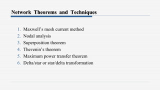
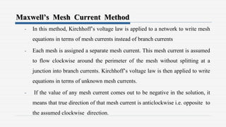
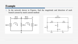
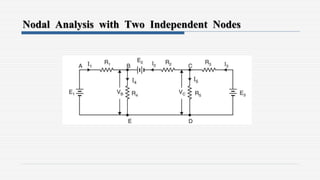
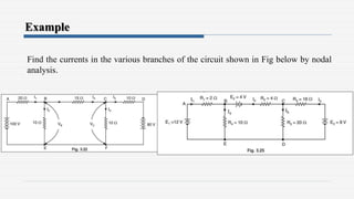
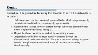
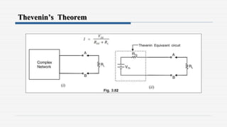
1. The document discusses various network theorems and techniques used to analyze electrical circuits, including Maxwell's mesh current method, nodal analysis, superposition theorem, Thevenin's theorem, and the maximum power transfer theorem.
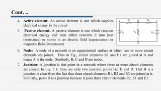
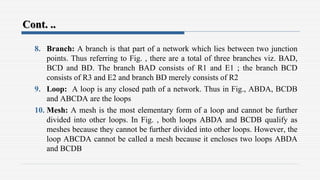
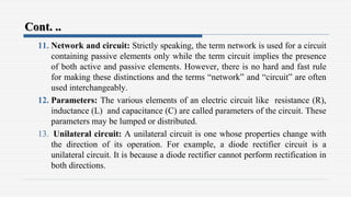
2. Key terms are defined, such as linear/non-linear circuits, active/passive elements, nodes, junctions, branches, loops, and meshes.
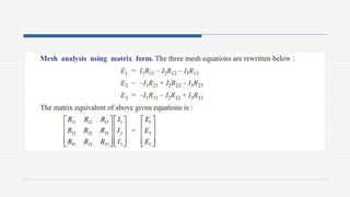
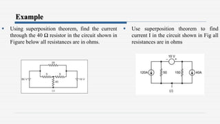
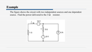
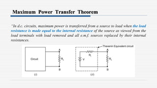
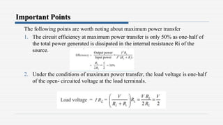
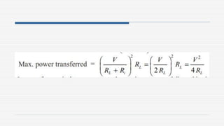
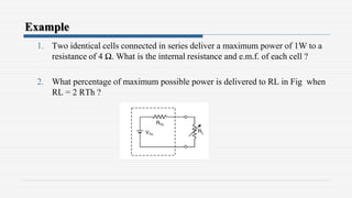
3. Examples are provided to demonstrate applying the theorems to solve for unknown currents and voltages in circuits. The maximum power transfer theorem states that maximum power is transferred when the load resistance equals the internal resistance of the source.


![[Deck] What's New in Spark-Iceberg Integration via DSV2.pptx](https://cdn.slidesharecdn.com/ss_thumbnails/deckwhatsnewinspark-icebergintegrationviadsv2-260210005337-25955b12-thumbnail.jpg?width=640&height=640&fit=bounds)

