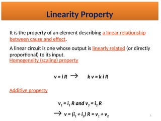
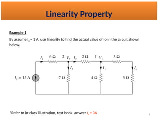
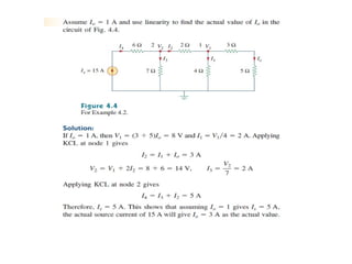
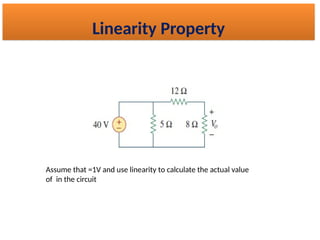
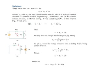
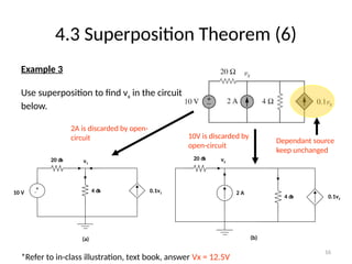
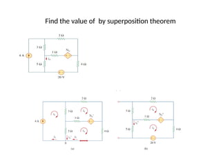
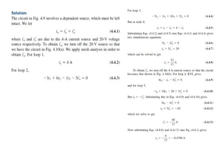
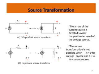
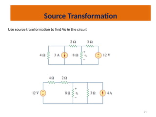
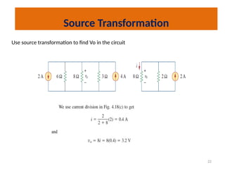
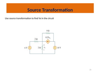
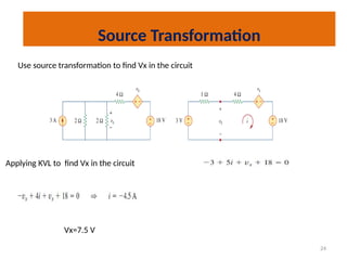
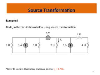
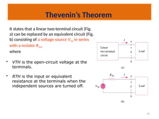
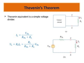
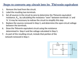
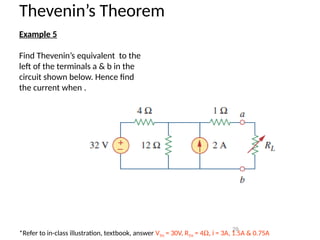
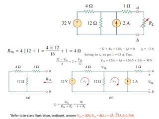
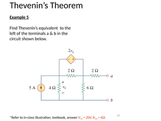
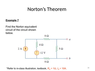
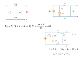
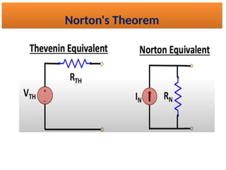
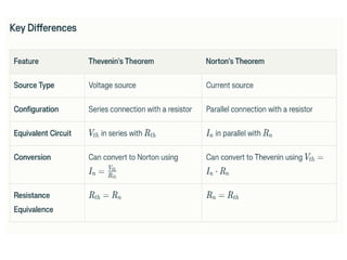
By Lt Col Imran Nazir
Linear Circuit Analysis(LCA)
EE-111
Lecture-5
3
Methods of Analysis
 Linearity Property
 Superposition
 Source Transformation
 Thevenin's Theorem
 Norton's Theorem
 Maximum Power Transfer
Linearity Property
 A linear Circuit is one whose output is linearly
related (or directly proportional ) to its input
5
It is the property of an element describing a linear relationship
between cause and effect.
A linear circuit is one whose output is linearly related (or directly
proportional) to its input.
Homogeneity (scaling) property
v = i R → k v = k i R
Additive property
v1 = i1 R and v2 = i2 R
→ v = (i1 + i2) R = v1 + v2
Linearity Property
6
Example 1
By assume Io = 1 A, use linearity to find the actual value of Io in the circuit shown
below.
*Refer to in-class illustration, text book, answer Io = 3A
Linearity Property
Assume that =1V and use linearity to calculate the actual value
of in the circuit
Linearity Property
9
It states that the voltage across (or current through) an element
in a linear circuit is the algebraic sum of the voltage across (or
currents through) that element due to EACH independent
source acting alone.
The principle of superposition helps us to analyze a linear
circuit with more than one independent source by calculating
the contribution of each independent source separately.
Superposition Theorem
11
4.3 Superposition Theorem (3)
Steps to apply superposition principle
1. Turn off all independent sources except one
source. Find the output (voltage or current)
due to that active source using nodal or
mesh analysis.
2. Repeat step 1 for each of the other independent
sources.
3. Find the total contribution by adding
algebraically all the contributions due to the
independent sources.
12
Two things have to be keep in mind:
1. When we say turn off all other independent sources:
 Independent voltage sources are replaced by 0 V
(short circuit) and
 Independent current sources are replaced by 0 A
(open circuit).
2. Dependent sources are left intact because they are
controlled by circuit variables.
Differences Between Super Mesh/Node Analysis and Superposition Analysis
14
4.3 Superposition Theorem (5)
Example 2
Use the superposition theorem to find v in the
circuit shown below.
3A is discarded by
open-circuit
6V is discarded by
short-circuit
*Refer to in-class illustration, text book, answer v = 10V
16
4.3 Superposition Theorem (6)
Example 3
Use superposition to find vx in the circuit
below.
*Refer to in-class illustration, text book, answer Vx = 12.5V
2A is discarded by open-
circuit
20  v1
4 
10 V
+

(a)
0.1v1
4 
2 A
(b)
20 
0.1v2
v2
10V is discarded by
open-circuit
Dependant source
keep unchanged
Find the value of by superposition theorem
19
Source Transformation
• An equivalent circuit is one whose v-i characteristics
are identical with the original circuit.
• It is the process of replacing a voltage source vS in
series with a resistor R by a current source iS in
parallel with a resistor R, or vice versa.
20
(a) Independent source transform
(b) Dependent source transform
•The arrow of the
current source is
directed toward
the positive terminal of
the voltage source.
•The source
transformation is not
possible when R = 0 for
voltage source and R = ∞
for current source.
+
+
+
+
-
-
-
-
Source Transformation
21
Source Transformation
Use source transformation to find Vo in the circuit
22
Source Transformation
Use source transformation to find Vo in the circuit
23
Source Transformation
Use source transformation to find Vx in the circuit
24
Source Transformation
Use source transformation to find Vx in the circuit
Applying KVL to find Vx in the circuit
Vx=7.5 V
25
Example 4
Find io in the circuit shown below using source transformation.
*Refer to in-class illustration, textbook, answer io = 1.78A
Source Transformation
26
It states that a linear two-terminal circuit (Fig.
a) can be replaced by an equivalent circuit (Fig.
b) consisting of a voltage source VTH in series
with a resistor RTH,
where
• VTH is the open-circuit voltage at the
terminals.
• RTH is the input or equivalent
resistance at the terminals when the
independent sources are turned off.
Thevenin’s Theorem
 Thevenin equivalent is a simple voltage
divider.
Steps to converts any circuit into its Thévenin equivalent
1. Remove the load from the circuit.
2. Label the resulting two terminals.
3. Set all sources in the circuit to zero to determine the Thévenin equivalent
resistance, RTh, by calculating the resistance “seen” between terminals ‘a’ and
‘b’. It may be necessary to redraw the circuit to simplify this step
5. Replace the sources removed in Step 3, and determine the open-circuit voltage
between the terminals.
6. Draw the Thévenin equivalent circuit using the resistance
determined in Step 4 and the voltage calculated in Step 5.
7. As part of the resulting circuit, include that portion of the
network removed in Step 1
29
Thevenin’s Theorem
Example 5
Find Thevenin’s equivalent to the
left of the terminals a & b in the
circuit shown below. Hence find
the current when .
*Refer to in-class illustration, textbook, answer VTH = 30V, RTH = 4W, i = 3A, 1.5A & 0.75A
30
*Refer to in-class illustration, textbook, answer VTH = 30V, RTH = 4W, i = 3A, 1.5A & 0.75A
31
Thevenin’s Theorem
Example 5
Find Thevenin’s equivalent to the
left of the terminals a & b in the
circuit shown below.
*Refer to in-class illustration, textbook, answer VTH = 20V, RTH = 6W
32
*Refer to in-class illustration, textbook, answer VTH = 20V, RTH = 6W
33
Norton’s Theorem
It states that a linear two-terminal circuit can be
replaced by an equivalent circuit of a current
source IN in parallel with a resistor RN,
Where
• IN is the short circuit current through
the terminals.
• RN is the input or equivalent resistance
at the terminals when the independent
sources are turned off.
The Thevenin’s and Norton equivalent circuits are related
by a source transformation.
Steps to convert cct in to Norten’s equivalent
1. Remove the load from the circuit.
2. Label the resulting two terminals. We will label them as a and b.
3. Set all sources to zero !
4. Determine the Norton equivalent resistance, RN. It may be necessary to
redraw the circuit to simplify this step.
5. Replace the sources removed in Step 3, and determine the current which
would occur in a short if the short were connected between terminals a
and b. If the original circuit has more than one source, it may be
necessary to use the Superposition Theorem.
6. Sketch the Norton equivalent circuit using the resistance determined in
Step 4 and the current calculated in Step 5. As part of the resulting
circuit, include that portion of the network removed in Step 1.
36
Norton’s Theorem
Example 7
Find the Norton equivalent
circuit of the circuit shown
below.
*Refer to in-class illustration, textbook, RN = 1W, IN = 10A.
• Thevenin's Theorem states that any linear electrical network
can be reduced to an equivalent circuit consisting of a single
voltage source (Vth) in series with a resistor (Rth​
)
• This theorem is particularly useful for analyzing circuits with
multiple voltage sources and resistors by converting them into
a simpler form
Thevenin's Theorem
• Norton's Theorem, states that linear network can be
represented as an equivalent circuit consisting of a single
current source (In) in parallel with a resistor (Rn​
)
Norton's Theorem
Norton's Theorem
THANK YOU

Lca Linearity property Lecture 005 .pptx

  • 2.
    By Lt ColImran Nazir Linear Circuit Analysis(LCA) EE-111 Lecture-5
  • 3.
    3 Methods of Analysis Linearity Property  Superposition  Source Transformation  Thevenin's Theorem  Norton's Theorem  Maximum Power Transfer
  • 4.
    Linearity Property  Alinear Circuit is one whose output is linearly related (or directly proportional ) to its input
  • 5.
    5 It is theproperty of an element describing a linear relationship between cause and effect. A linear circuit is one whose output is linearly related (or directly proportional) to its input. Homogeneity (scaling) property v = i R → k v = k i R Additive property v1 = i1 R and v2 = i2 R → v = (i1 + i2) R = v1 + v2 Linearity Property
  • 6.
    6 Example 1 By assumeIo = 1 A, use linearity to find the actual value of Io in the circuit shown below. *Refer to in-class illustration, text book, answer Io = 3A Linearity Property
  • 8.
    Assume that =1Vand use linearity to calculate the actual value of in the circuit Linearity Property
  • 9.
    9 It states thatthe voltage across (or current through) an element in a linear circuit is the algebraic sum of the voltage across (or currents through) that element due to EACH independent source acting alone. The principle of superposition helps us to analyze a linear circuit with more than one independent source by calculating the contribution of each independent source separately. Superposition Theorem
  • 10.
    11 4.3 Superposition Theorem(3) Steps to apply superposition principle 1. Turn off all independent sources except one source. Find the output (voltage or current) due to that active source using nodal or mesh analysis. 2. Repeat step 1 for each of the other independent sources. 3. Find the total contribution by adding algebraically all the contributions due to the independent sources.
  • 11.
    12 Two things haveto be keep in mind: 1. When we say turn off all other independent sources:  Independent voltage sources are replaced by 0 V (short circuit) and  Independent current sources are replaced by 0 A (open circuit). 2. Dependent sources are left intact because they are controlled by circuit variables.
  • 12.
    Differences Between SuperMesh/Node Analysis and Superposition Analysis
  • 13.
    14 4.3 Superposition Theorem(5) Example 2 Use the superposition theorem to find v in the circuit shown below. 3A is discarded by open-circuit 6V is discarded by short-circuit *Refer to in-class illustration, text book, answer v = 10V
  • 15.
    16 4.3 Superposition Theorem(6) Example 3 Use superposition to find vx in the circuit below. *Refer to in-class illustration, text book, answer Vx = 12.5V 2A is discarded by open- circuit 20  v1 4  10 V +  (a) 0.1v1 4  2 A (b) 20  0.1v2 v2 10V is discarded by open-circuit Dependant source keep unchanged
  • 16.
    Find the valueof by superposition theorem
  • 18.
    19 Source Transformation • Anequivalent circuit is one whose v-i characteristics are identical with the original circuit. • It is the process of replacing a voltage source vS in series with a resistor R by a current source iS in parallel with a resistor R, or vice versa.
  • 19.
    20 (a) Independent sourcetransform (b) Dependent source transform •The arrow of the current source is directed toward the positive terminal of the voltage source. •The source transformation is not possible when R = 0 for voltage source and R = ∞ for current source. + + + + - - - - Source Transformation
  • 20.
    21 Source Transformation Use sourcetransformation to find Vo in the circuit
  • 21.
    22 Source Transformation Use sourcetransformation to find Vo in the circuit
  • 22.
    23 Source Transformation Use sourcetransformation to find Vx in the circuit
  • 23.
    24 Source Transformation Use sourcetransformation to find Vx in the circuit Applying KVL to find Vx in the circuit Vx=7.5 V
  • 24.
    25 Example 4 Find ioin the circuit shown below using source transformation. *Refer to in-class illustration, textbook, answer io = 1.78A Source Transformation
  • 25.
    26 It states thata linear two-terminal circuit (Fig. a) can be replaced by an equivalent circuit (Fig. b) consisting of a voltage source VTH in series with a resistor RTH, where • VTH is the open-circuit voltage at the terminals. • RTH is the input or equivalent resistance at the terminals when the independent sources are turned off. Thevenin’s Theorem
  • 26.
     Thevenin equivalentis a simple voltage divider.
  • 27.
    Steps to convertsany circuit into its Thévenin equivalent 1. Remove the load from the circuit. 2. Label the resulting two terminals. 3. Set all sources in the circuit to zero to determine the Thévenin equivalent resistance, RTh, by calculating the resistance “seen” between terminals ‘a’ and ‘b’. It may be necessary to redraw the circuit to simplify this step 5. Replace the sources removed in Step 3, and determine the open-circuit voltage between the terminals. 6. Draw the Thévenin equivalent circuit using the resistance determined in Step 4 and the voltage calculated in Step 5. 7. As part of the resulting circuit, include that portion of the network removed in Step 1
  • 28.
    29 Thevenin’s Theorem Example 5 FindThevenin’s equivalent to the left of the terminals a & b in the circuit shown below. Hence find the current when . *Refer to in-class illustration, textbook, answer VTH = 30V, RTH = 4W, i = 3A, 1.5A & 0.75A
  • 29.
    30 *Refer to in-classillustration, textbook, answer VTH = 30V, RTH = 4W, i = 3A, 1.5A & 0.75A
  • 30.
    31 Thevenin’s Theorem Example 5 FindThevenin’s equivalent to the left of the terminals a & b in the circuit shown below. *Refer to in-class illustration, textbook, answer VTH = 20V, RTH = 6W
  • 31.
    32 *Refer to in-classillustration, textbook, answer VTH = 20V, RTH = 6W
  • 32.
    33 Norton’s Theorem It statesthat a linear two-terminal circuit can be replaced by an equivalent circuit of a current source IN in parallel with a resistor RN, Where • IN is the short circuit current through the terminals. • RN is the input or equivalent resistance at the terminals when the independent sources are turned off. The Thevenin’s and Norton equivalent circuits are related by a source transformation.
  • 34.
    Steps to convertcct in to Norten’s equivalent 1. Remove the load from the circuit. 2. Label the resulting two terminals. We will label them as a and b. 3. Set all sources to zero ! 4. Determine the Norton equivalent resistance, RN. It may be necessary to redraw the circuit to simplify this step. 5. Replace the sources removed in Step 3, and determine the current which would occur in a short if the short were connected between terminals a and b. If the original circuit has more than one source, it may be necessary to use the Superposition Theorem. 6. Sketch the Norton equivalent circuit using the resistance determined in Step 4 and the current calculated in Step 5. As part of the resulting circuit, include that portion of the network removed in Step 1.
  • 35.
    36 Norton’s Theorem Example 7 Findthe Norton equivalent circuit of the circuit shown below. *Refer to in-class illustration, textbook, RN = 1W, IN = 10A.
  • 37.
    • Thevenin's Theoremstates that any linear electrical network can be reduced to an equivalent circuit consisting of a single voltage source (Vth) in series with a resistor (Rth​ ) • This theorem is particularly useful for analyzing circuits with multiple voltage sources and resistors by converting them into a simpler form Thevenin's Theorem
  • 38.
    • Norton's Theorem,states that linear network can be represented as an equivalent circuit consisting of a single current source (In) in parallel with a resistor (Rn​ ) Norton's Theorem
  • 39.
  • 41.