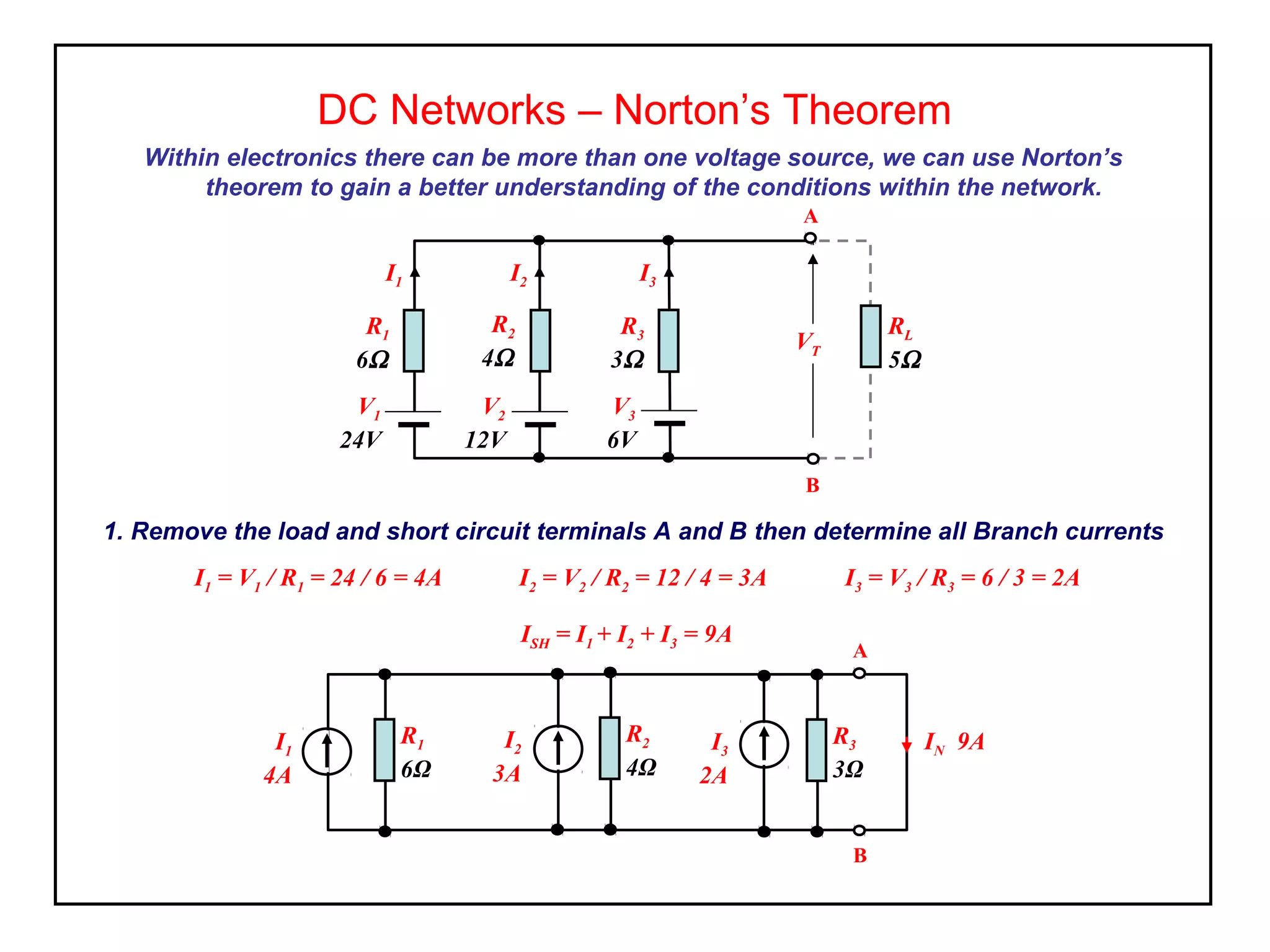
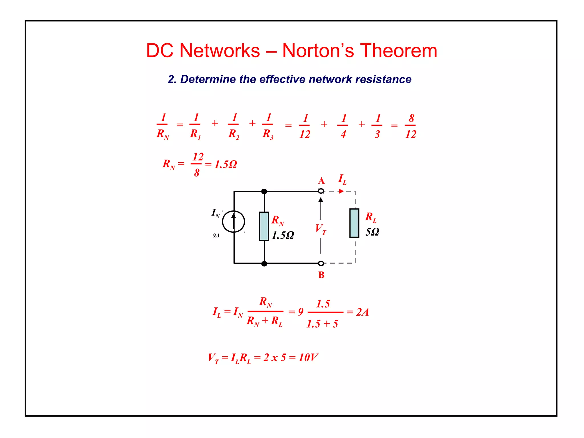
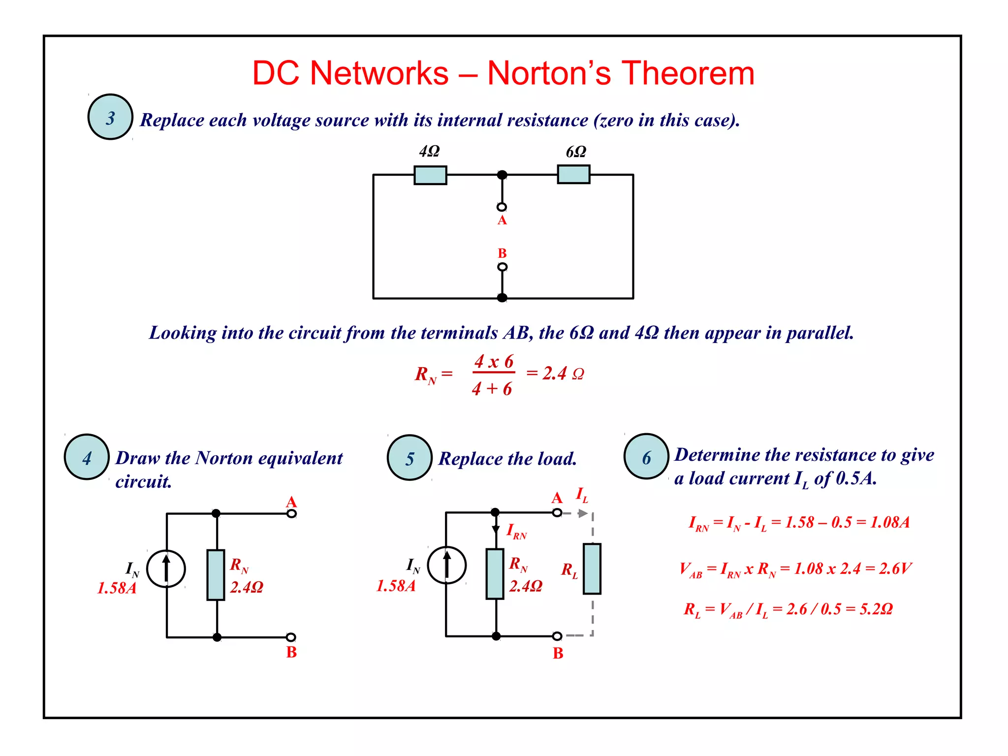
DC Networks – Norton’s Theorem
Norton’s theorem complements Thevenin’s by replacing the network with a
constant current generator (ISC ) and a parallel internal resistance RO
The current ISC is the current that would flow between the terminals (AB) if short
circuited.
The internal resistance is equal to the resistance which appears across the
open-circuited branch terminals and is defined in the same way as for the
Thevenin circuit.
Norton’s theorem can be used to transpose voltage driven networks into
current driven networks.
E
rint
R1
A
B
R2
= RO
A
B
R2
IN
DC Networks – Norton’s Theorem
Use the following procedure to obtain the Norton equivalent for the circuit shown,
1. short circuit branch AB,
2. determine the short circuit current, ISC
E = 20V
R2 = 8Ω
A
B
R3 = 15Ω
R3 = 4Ω
R1 = 2Ω
E = 20V
R2= 8Ω
A
B
R3 = 4Ω
ISC
R1 = 2Ω
DC Networks – Norton’s Theorem
3. remove each source of emf and replace them with their internal resistances
4. determine the Norton equivalent resistance, RN ‘looking in’ at the break,
5. replace the internal resistance with the short circuit current source (ISC ) and the Norton
equivalent resistance (RO ) in parallel with the current source, (fig. a).
6. connect the load to the AB terminals of the Norton equivalent circuit and using the current
divider theorem determine the current flowing in the load (I in fig b).
rint = 2Ω R1= 8Ω
A
B
R2 = 4Ω
RN
RN
A
B
(a)
IN
RLOAD
I
RN
A
B
(b)
IN
Activity
1. For the example shown use Norton’s theorem to derive the terminal voltage VT .
DC Networks – Norton’s Theorem
R=20Ω
rint = 1Ω
E = 48V
R2 = 2Ω
R1=10Ω VT
A
B
2. For the example shown use Norton’s theorem to derive the terminal voltage VT .
RL= 5Ω24V
3Ω
12Ω V
A
B
6Ω VT
Norton’s theorem can be used to simplify the calculations for varying load
conditions.
Within electronics there can be more than one voltage source, we can use Norton’s
theorem to gain a better understanding of the conditions within the network.
DC Networks – Norton’s Theorem
RL
5Ω
V1
24V
R1
6Ω
V2
12V
R2
4Ω
V3
6V
R3
3Ω
A
B
VT
I1 I2 I3
I1 = V1 / R1 = 24 / 6 = 4A I2 = V2 / R2 = 12 / 4 = 3A I3 = V3 / R3 = 6 / 3 = 2A
1. Remove the load and short circuit terminals A and B then determine all Branch currents
R1
6Ω
A
B
I1
4A
R2
4Ω
I2
3A
R3
3Ω
I3
2A
IN 9A
ISH = I1 + I2 + I3 = 9A
DC Networks – Norton’s Theorem
2. Determine the effective network resistance
1
RN
=
1
R1
1
R2
1
R3
+ + =
1
12
1
4
1
3
+ + =
8
12
RN =
12
8
= 1.5Ω
IL
IL = IN
RN
RN + RL
= 9
1.5
1.5 + 5
= 2A
VT = ILRL = 2 x 5 = 10V
RN
1.5Ω
RL
5Ω
A
B
VT
IN
9A
Activity
Use Norton’s theorem to evaluate the terminal voltage (VT ) and the current through the
load resistance (IL ).
DC Networks – Norton’s Theorem
R4
2Ω
RL
10Ω
V1
6V
R1
1Ω
V2
10V
R2
2Ω
V3
8V
R3
4Ω
VT
I1 I2 I3
IL
Obtain the Norton equivalent circuit for the network shown and determine the value of load
resistor required for a current of 0.5A to flow between terminals AB.
DC Networks – Norton’s Theorem
R1 = 4Ω
E1 = 5V B
A
R2 = 6Ω
E2 = 2V
-
+
R1 = 4Ω
B
A
R2 = 6Ω
5V
-
+
2V
1 2 Determine branch currentsShort circuit the output (AB)
ISH
I1 I2
I1 =
ISH = I1 + I2 = 1.58A
E1
R1
5
4
= A
I2 =
E2
R2
2
6= A
DC Networks – Norton’s Theorem
4Ω
B
A
6Ω
Replace each voltage source with its internal resistance (zero in this case).
Looking into the circuit from the terminals AB, the 6Ω and 4Ω then appear in parallel.
4 x 6
4 + 6
= 2.4 ΩRN =
3
Draw the Norton equivalent
circuit.
4 Replace the load.5
RN
2.4Ω
A
B
1.58A
Determine the resistance to give
a load current IL of 0.5A.
6
1.58A
RN
2.4Ω
A
RN
2.4Ω
RL
B
IL
IRN
IRN = IN - IL = 1.58 – 0.5 = 1.08A
VAB = IRN x RN = 1.08 x 2.4 = 2.6V
RL = VAB / IL = 2.6 / 0.5 = 5.2Ω
IN
IN

Elect principles 2 nortons theorem

  • 1.
    DC Networks –Norton’s Theorem Norton’s theorem complements Thevenin’s by replacing the network with a constant current generator (ISC ) and a parallel internal resistance RO The current ISC is the current that would flow between the terminals (AB) if short circuited. The internal resistance is equal to the resistance which appears across the open-circuited branch terminals and is defined in the same way as for the Thevenin circuit. Norton’s theorem can be used to transpose voltage driven networks into current driven networks. E rint R1 A B R2 = RO A B R2 IN
  • 2.
    DC Networks –Norton’s Theorem Use the following procedure to obtain the Norton equivalent for the circuit shown, 1. short circuit branch AB, 2. determine the short circuit current, ISC E = 20V R2 = 8Ω A B R3 = 15Ω R3 = 4Ω R1 = 2Ω E = 20V R2= 8Ω A B R3 = 4Ω ISC R1 = 2Ω
  • 3.
    DC Networks –Norton’s Theorem 3. remove each source of emf and replace them with their internal resistances 4. determine the Norton equivalent resistance, RN ‘looking in’ at the break, 5. replace the internal resistance with the short circuit current source (ISC ) and the Norton equivalent resistance (RO ) in parallel with the current source, (fig. a). 6. connect the load to the AB terminals of the Norton equivalent circuit and using the current divider theorem determine the current flowing in the load (I in fig b). rint = 2Ω R1= 8Ω A B R2 = 4Ω RN RN A B (a) IN RLOAD I RN A B (b) IN
  • 4.
    Activity 1. For theexample shown use Norton’s theorem to derive the terminal voltage VT . DC Networks – Norton’s Theorem R=20Ω rint = 1Ω E = 48V R2 = 2Ω R1=10Ω VT A B 2. For the example shown use Norton’s theorem to derive the terminal voltage VT . RL= 5Ω24V 3Ω 12Ω V A B 6Ω VT Norton’s theorem can be used to simplify the calculations for varying load conditions.
  • 5.
    Within electronics therecan be more than one voltage source, we can use Norton’s theorem to gain a better understanding of the conditions within the network. DC Networks – Norton’s Theorem RL 5Ω V1 24V R1 6Ω V2 12V R2 4Ω V3 6V R3 3Ω A B VT I1 I2 I3 I1 = V1 / R1 = 24 / 6 = 4A I2 = V2 / R2 = 12 / 4 = 3A I3 = V3 / R3 = 6 / 3 = 2A 1. Remove the load and short circuit terminals A and B then determine all Branch currents R1 6Ω A B I1 4A R2 4Ω I2 3A R3 3Ω I3 2A IN 9A ISH = I1 + I2 + I3 = 9A
  • 6.
    DC Networks –Norton’s Theorem 2. Determine the effective network resistance 1 RN = 1 R1 1 R2 1 R3 + + = 1 12 1 4 1 3 + + = 8 12 RN = 12 8 = 1.5Ω IL IL = IN RN RN + RL = 9 1.5 1.5 + 5 = 2A VT = ILRL = 2 x 5 = 10V RN 1.5Ω RL 5Ω A B VT IN 9A
  • 7.
    Activity Use Norton’s theoremto evaluate the terminal voltage (VT ) and the current through the load resistance (IL ). DC Networks – Norton’s Theorem R4 2Ω RL 10Ω V1 6V R1 1Ω V2 10V R2 2Ω V3 8V R3 4Ω VT I1 I2 I3 IL
  • 8.
    Obtain the Nortonequivalent circuit for the network shown and determine the value of load resistor required for a current of 0.5A to flow between terminals AB. DC Networks – Norton’s Theorem R1 = 4Ω E1 = 5V B A R2 = 6Ω E2 = 2V - + R1 = 4Ω B A R2 = 6Ω 5V - + 2V 1 2 Determine branch currentsShort circuit the output (AB) ISH I1 I2 I1 = ISH = I1 + I2 = 1.58A E1 R1 5 4 = A I2 = E2 R2 2 6= A
  • 9.
    DC Networks –Norton’s Theorem 4Ω B A 6Ω Replace each voltage source with its internal resistance (zero in this case). Looking into the circuit from the terminals AB, the 6Ω and 4Ω then appear in parallel. 4 x 6 4 + 6 = 2.4 ΩRN = 3 Draw the Norton equivalent circuit. 4 Replace the load.5 RN 2.4Ω A B 1.58A Determine the resistance to give a load current IL of 0.5A. 6 1.58A RN 2.4Ω A RN 2.4Ω RL B IL IRN IRN = IN - IL = 1.58 – 0.5 = 1.08A VAB = IRN x RN = 1.08 x 2.4 = 2.6V RL = VAB / IL = 2.6 / 0.5 = 5.2Ω IN IN
  • 10.
    DC Networks –Norton’s Theorem 4Ω B A 6Ω Replace each voltage source with its internal resistance (zero in this case). Looking into the circuit from the terminals AB, the 6Ω and 4Ω then appear in parallel. 4 x 6 4 + 6 = 2.4 ΩRN = 3 Draw the Norton equivalent circuit. 4 Replace the load.5 RN 2.4Ω A B 1.58A Determine the resistance to give a load current IL of 0.5A. 6 1.58A RN 2.4Ω A RN 2.4Ω RL B IL IRN IRN = IN - IL = 1.58 – 0.5 = 1.08A VAB = IRN x RN = 1.08 x 2.4 = 2.6V RL = VAB / IL = 2.6 / 0.5 = 5.2Ω IN IN