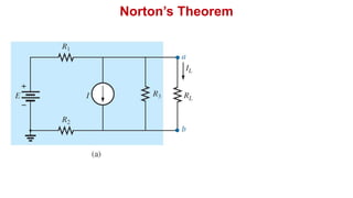
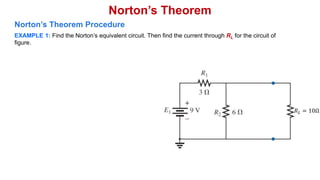
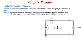
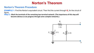
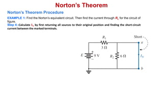
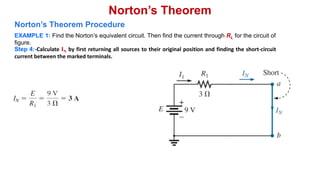
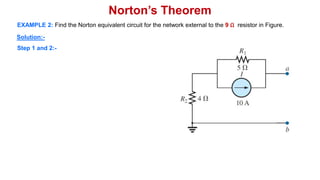
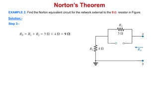
2. Norton’s Theorem
Norton’s theorem states that a linear two-terminal circuit can be replaced by
an equivalent circuit consisting of a current source IN in parallel with a
resistor RN, where IN is the short-circuit current through the terminals and RN
is the input or equivalent resistance at the terminals when the independent
sources are turned off.
5. Norton’s Theorem Procedure
EXAMPLE 1: Find the Norton’s equivalent circuit. Then find the current through RL for the circuit of
figure.
𝑅𝐿 = 10Ω
Norton’s Theorem
6. Step 1:- Remove that portion of the network where the Norton’s equivalent circuit is found. In Figure
below, this requires that the load resistor RL be temporarily removed from the network.
𝑅𝐿 = 10Ω
Norton’s Theorem
EXAMPLE 1: Find the Norton’s equivalent circuit. Then find the current through RL for the circuit of
figure.
Norton’s Theorem Procedure
7. Norton’s Theorem
EXAMPLE 1: Find the Norton’s equivalent circuit. Then find the current through RL for the circuit of
figure.
Step 1:- Remove that portion of the network where the Norton’s equivalent circuit is found. In Figure
below, this requires that the load resistor RL be temporarily removed from the network.
Norton’s Theorem Procedure
8. Step 2:- Mark the terminals of the remaining two-terminal network. (The importance of this step will
become obvious as we progress through some complex networks.)
Norton’s Theorem
EXAMPLE 1: Find the Norton’s equivalent circuit. Then find the current through RL for the circuit of
figure.
Norton’s Theorem Procedure
9. Step 3:-Calculate RN by first setting all sources to zero (voltage sources are replaced by short circuits, and
current sources by open circuits) and then finding the resultant resistance between the two
marked terminals.
Norton’s Theorem
EXAMPLE 1: Find the Norton’s equivalent circuit. Then find the current through RL for the circuit of
figure.
Norton’s Theorem Procedure
10. Step 4:-Calculate IN by first returning all sources to their original position and finding the short-circuit
current between the marked terminals.
Norton’s Theorem
EXAMPLE 1: Find the Norton’s equivalent circuit. Then find the current through RL for the circuit of
figure.
Norton’s Theorem Procedure
11. Step 4:-Calculate IN by first returning all sources to their original position and finding the short-circuit
current between the marked terminals.
Norton’s Theorem
EXAMPLE 1: Find the Norton’s equivalent circuit. Then find the current through RL for the circuit of
figure.
Norton’s Theorem Procedure
12. Step 4:-Calculate IN by first returning all sources to their original position and finding the short-circuit
current between the marked terminals.
Norton’s Theorem
EXAMPLE 1: Find the Norton’s equivalent circuit. Then find the current through RL for the circuit of
figure.
Norton’s Theorem Procedure
13. Step 4:-Calculate IN by first returning all sources to their original position and finding the short-circuit
current between the marked terminals.
Norton’s Theorem
EXAMPLE 1: Find the Norton’s equivalent circuit. Then find the current through RL for the circuit of
figure.
Norton’s Theorem Procedure
14. Step 5:-Draw the Norton’s equivalent circuit with the portion of the circuit previously removed replaced
between the terminals of the equivalent circuit.
Norton’s Theorem
EXAMPLE 1: Find the Norton’s equivalent circuit. Then find the current through RL for the circuit of
figure.
Norton’s Theorem Procedure
𝑰𝑵 = 𝟑𝑨
𝑹𝑵 = 𝟐Ω
= 10Ω
𝑰𝑳 =
𝑰𝑵𝑹𝑵
𝑹𝑵 + 𝑹𝑳
=
(𝟑𝑨)(𝟐Ω)
𝟐Ω + 𝟏𝟎Ω
=
𝟔
𝟏𝟐
= 𝟎. 𝟓 𝑨
15. Norton’s Theorem
EXAMPLE 1: Find the Norton’s equivalent circuit. Then find the current through RL for the circuit of
figure.
Converting the Norton equivalent circuit to a Thévenin equivalent circuit.
16. Norton’s Theorem
EXAMPLE 1: Find the Norton’s equivalent circuit. Then find the current through RL for the circuit of
figure.
Converting the Norton equivalent circuit to a Thévenin equivalent circuit.
𝑰𝑵 = 𝟑𝑨
𝑹𝑵 = 𝟐Ω
= 10Ω = 10Ω
= 𝑹𝑵= 𝟐Ω
𝑬𝑻𝒉 = 𝑰𝑵𝑹𝑵 = 𝟑𝑨 𝟐Ω = 𝟔𝑽
𝟔 𝑽
17. EXAMPLE 2: Find the Norton equivalent circuit for the network external to the 9 Ω resistor in Figure.
Norton’s Theorem
18. Step 1 and 2:-
Solution:-
Norton’s Theorem
EXAMPLE 2: Find the Norton equivalent circuit for the network external to the 9 Ω resistor in Figure.
23. Norton’s Theorem
𝑰𝑵 = 𝟓. 𝟓𝟔𝑨
𝑹𝑵 = 𝟗Ω
= 9Ω
𝑰𝑳 =
𝑰𝑵𝑹𝑵
𝑹𝑵 + 𝑹𝑳
=
(𝟓. 𝟓𝟔𝑨)(𝟗Ω)
𝟗Ω + 𝟗Ω
=
𝟓𝟎. 𝟎𝟒
𝟏𝟖
= 𝟐. 𝟕𝟖 𝑨
EXAMPLE 2: Find the Norton equivalent circuit for the network external to the 9 Ω resistor in Figure.
Solution:-
Step 5:-
Or 𝑰𝑳 =
𝑰𝑵
𝟐
=
𝟓. 𝟓𝟔𝑨
𝟐
== 𝟐. 𝟕𝟖 𝑨
24. References
Boylestad, Robert L. Introductory circuit analysis. Pearson Education, 2010.
Robbins, Allan H., and Wilhelm C. Miller. Circuit analysis: Theory and
practice. Cengage Learning, 2012.
Sadiku, Matthew NO, and Chales K. Alexander. Fundamentals of electric
circuits. McGraw-Hill Higher Education, 2007.