Downloaded 186 times
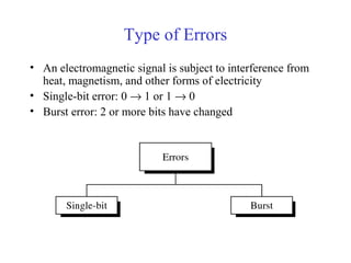
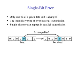
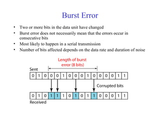

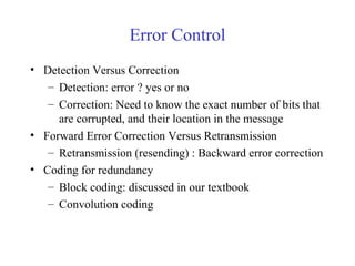
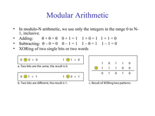
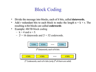
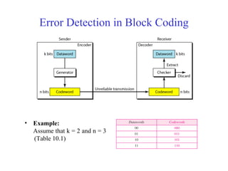
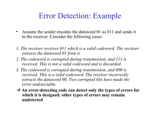
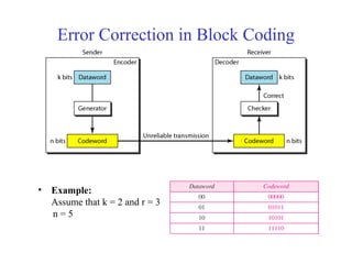
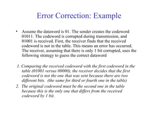
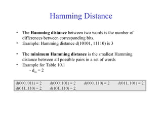
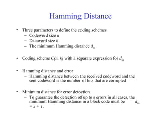
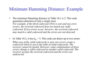
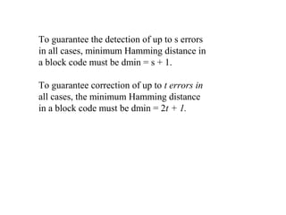

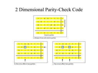
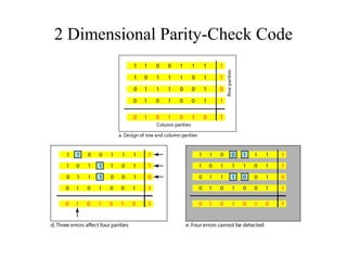
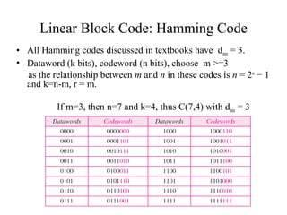
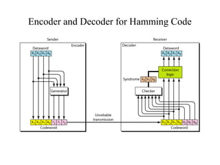
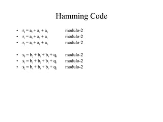
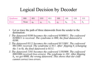
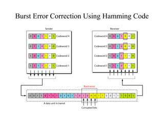
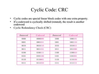
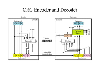

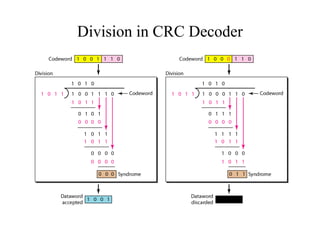
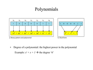
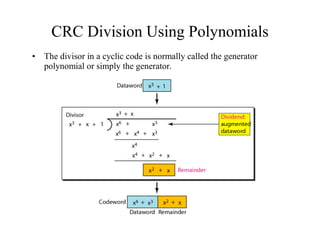
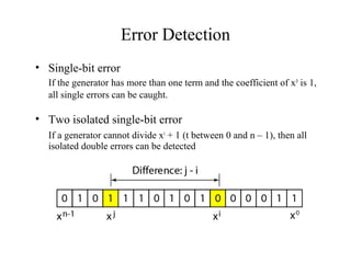
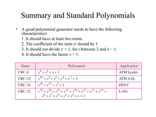
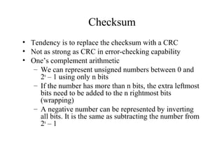
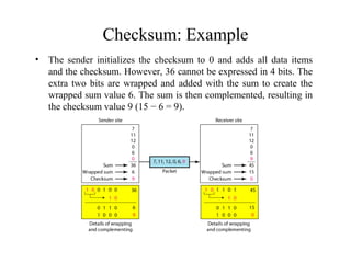
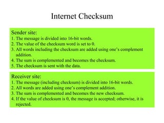

This document discusses various techniques for error detection and correction in digital communications. It begins by describing common types of errors like single-bit and burst errors. It then explains error detection methods like parity checks and cyclic redundancy checks (CRCs). CRCs use cyclic codes and polynomial division to detect errors. Block codes like Hamming codes can detect and correct errors by ensuring a minimum Hamming distance between codewords. Checksums are also discussed as a simpler error detection technique than CRCs. The document provides examples to illustrate how these different error control methods work.