Downloaded 161 times
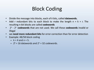
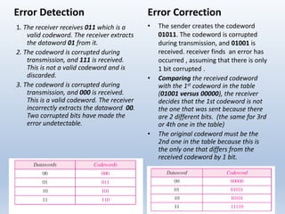
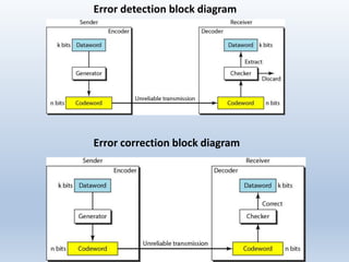
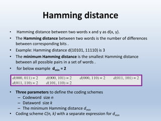
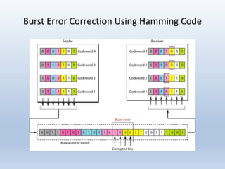
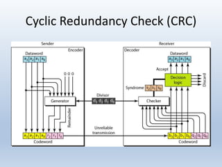
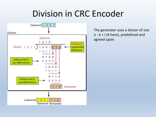
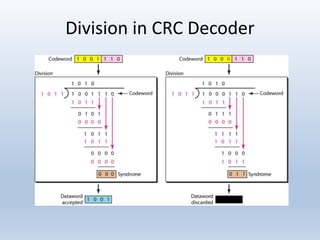

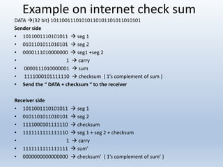

Chapter 10 covers error detection and correction in data communication, highlighting types of errors like single-bit and burst errors. It explains redundancy mechanisms for error detection and correction methodologies, including forward error correction and retransmission. Additionally, it discusses various coding techniques, Hamming distance for error detection/correction, cyclic redundancy checks, and checksum calculations.