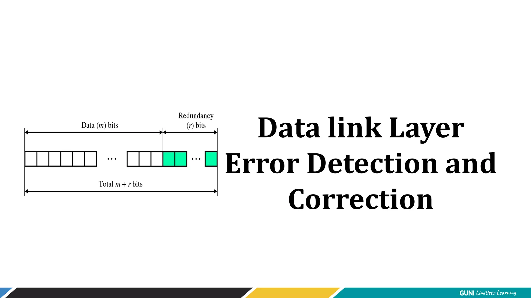
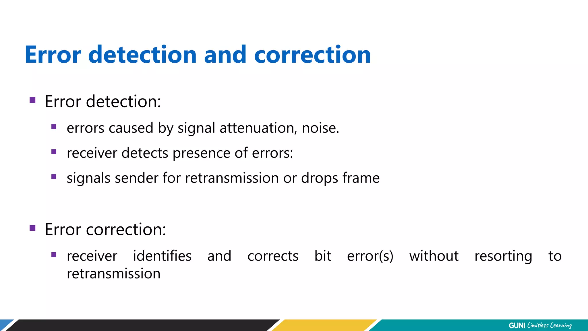
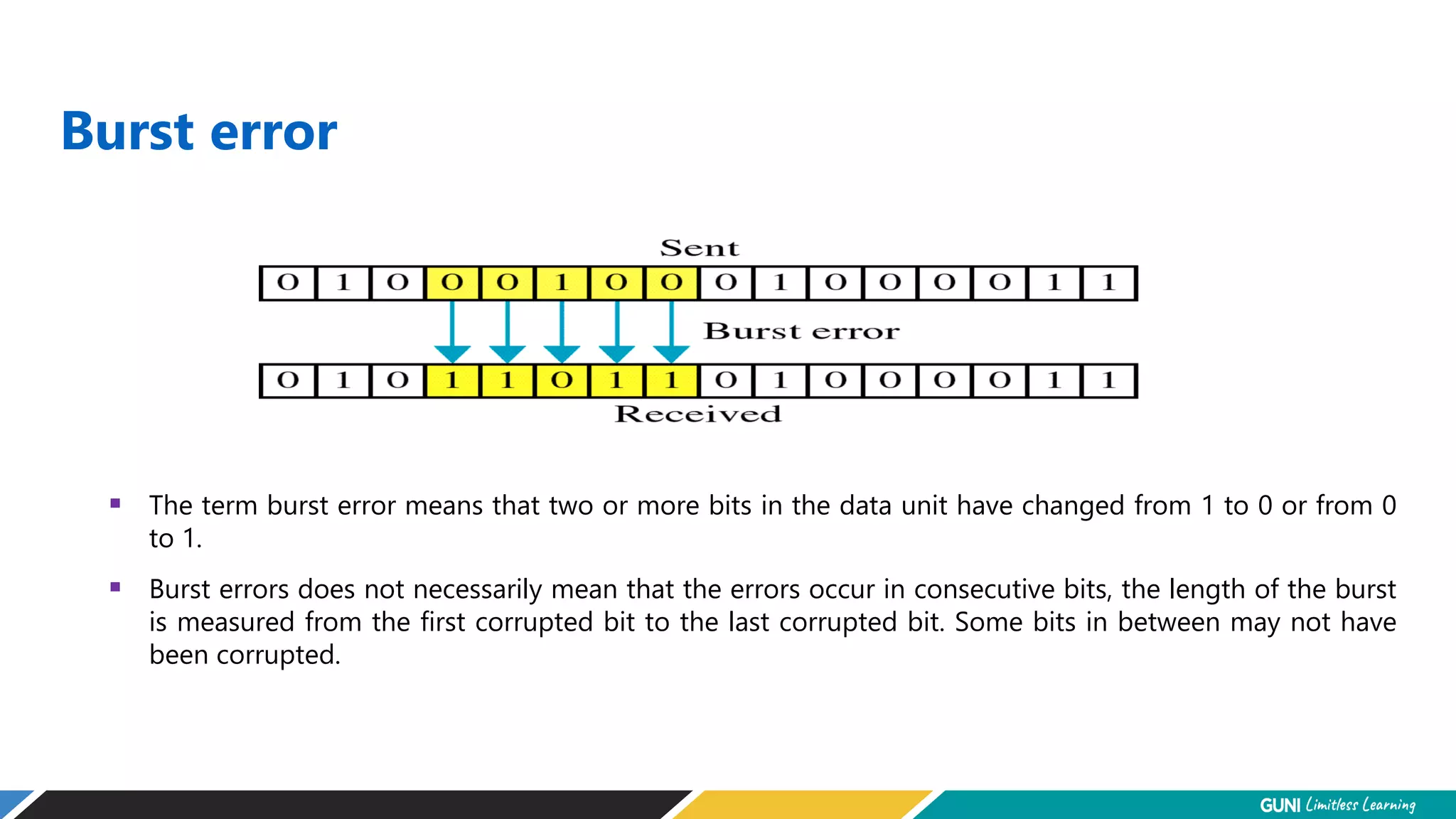
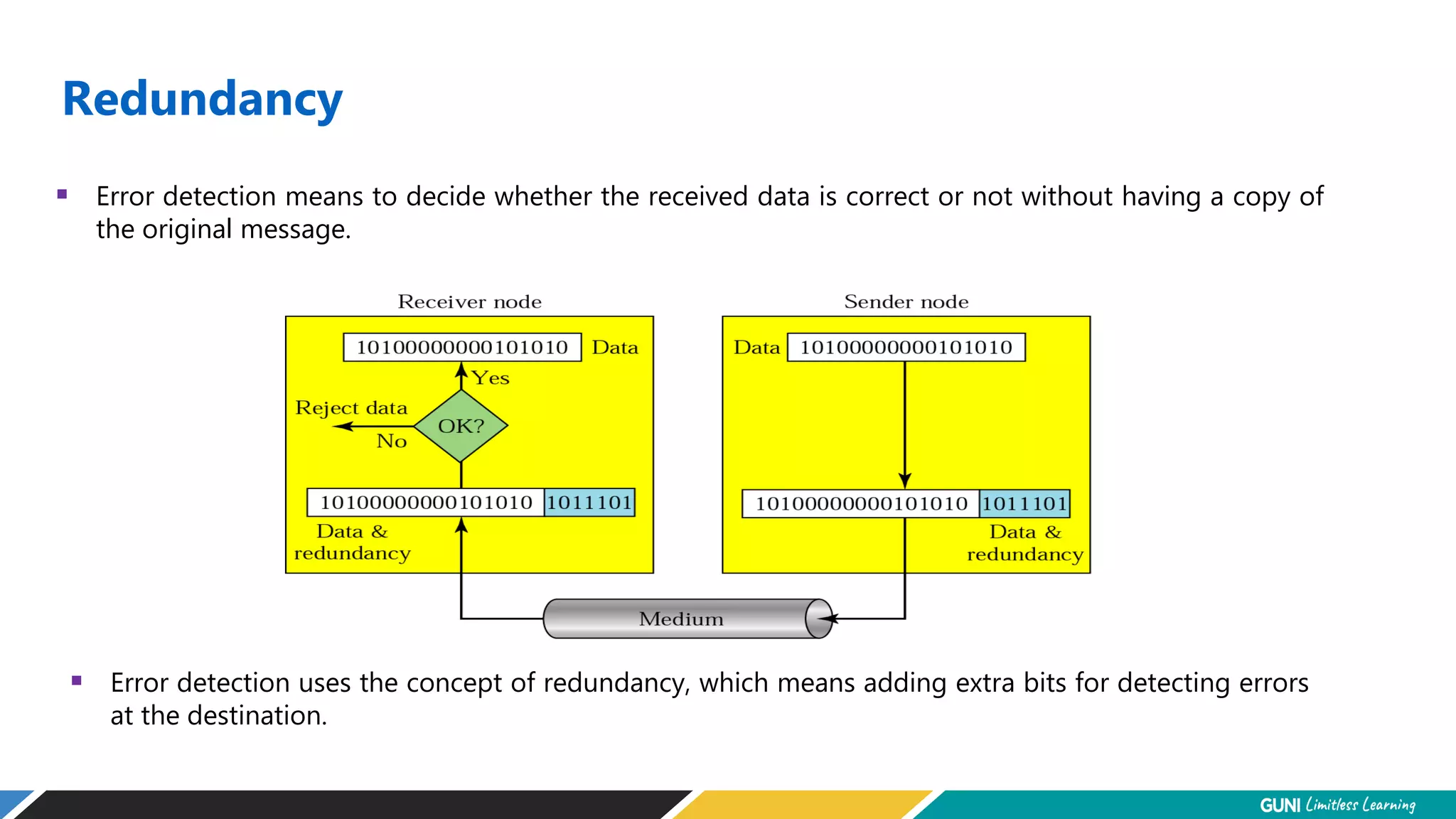
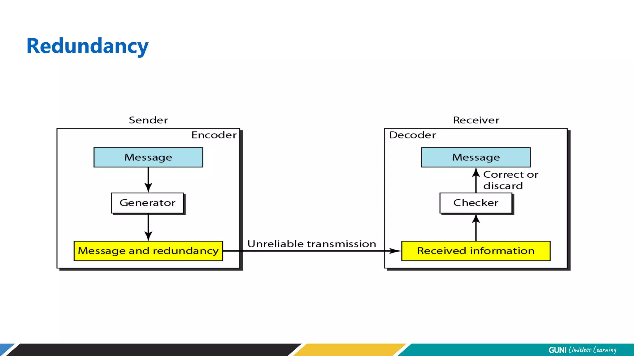
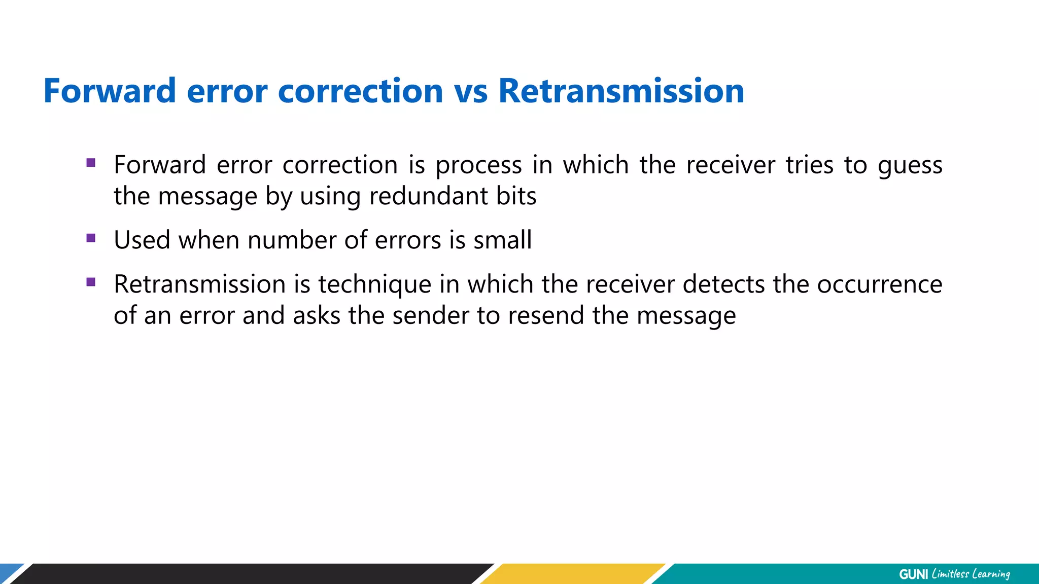
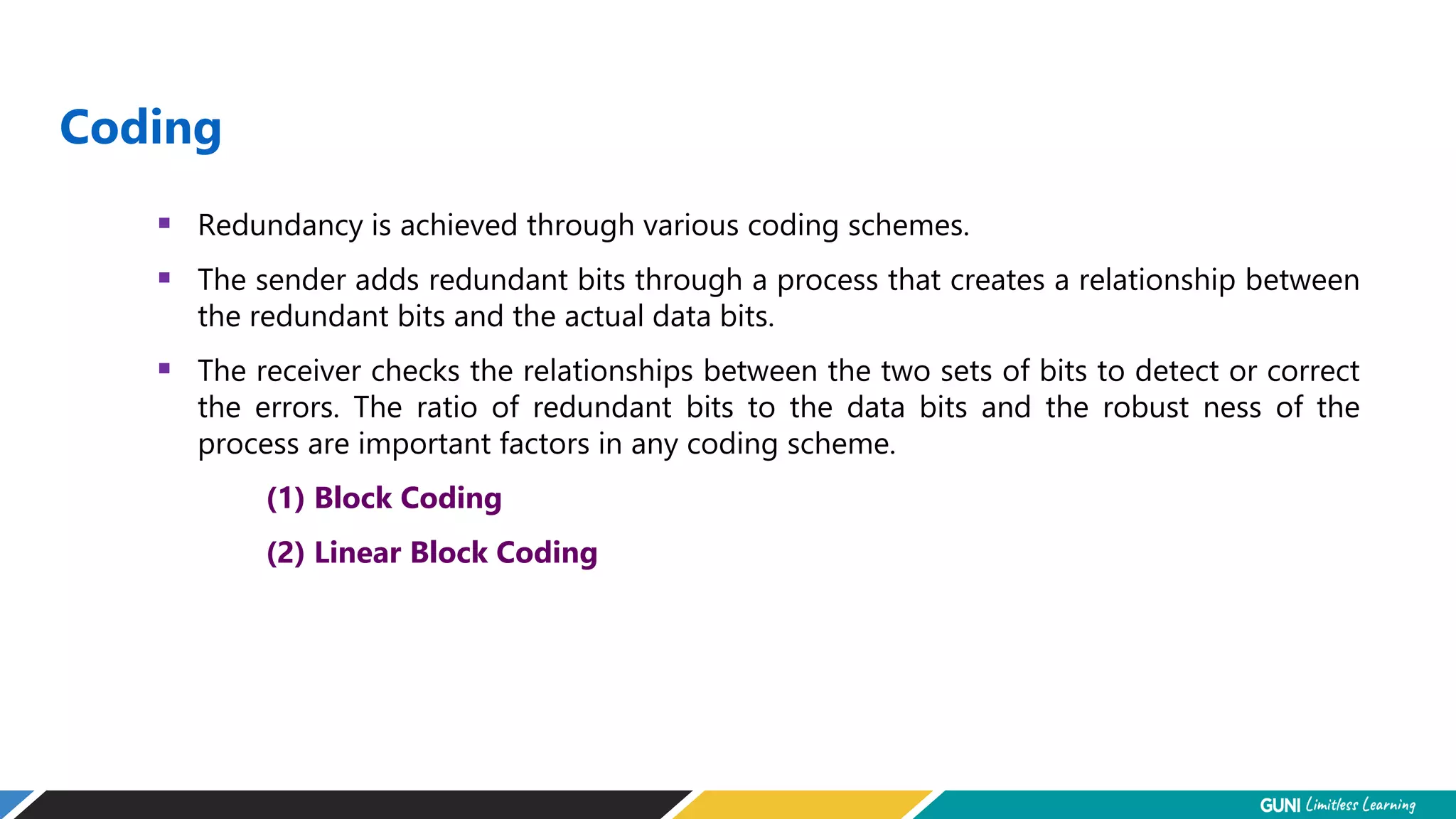
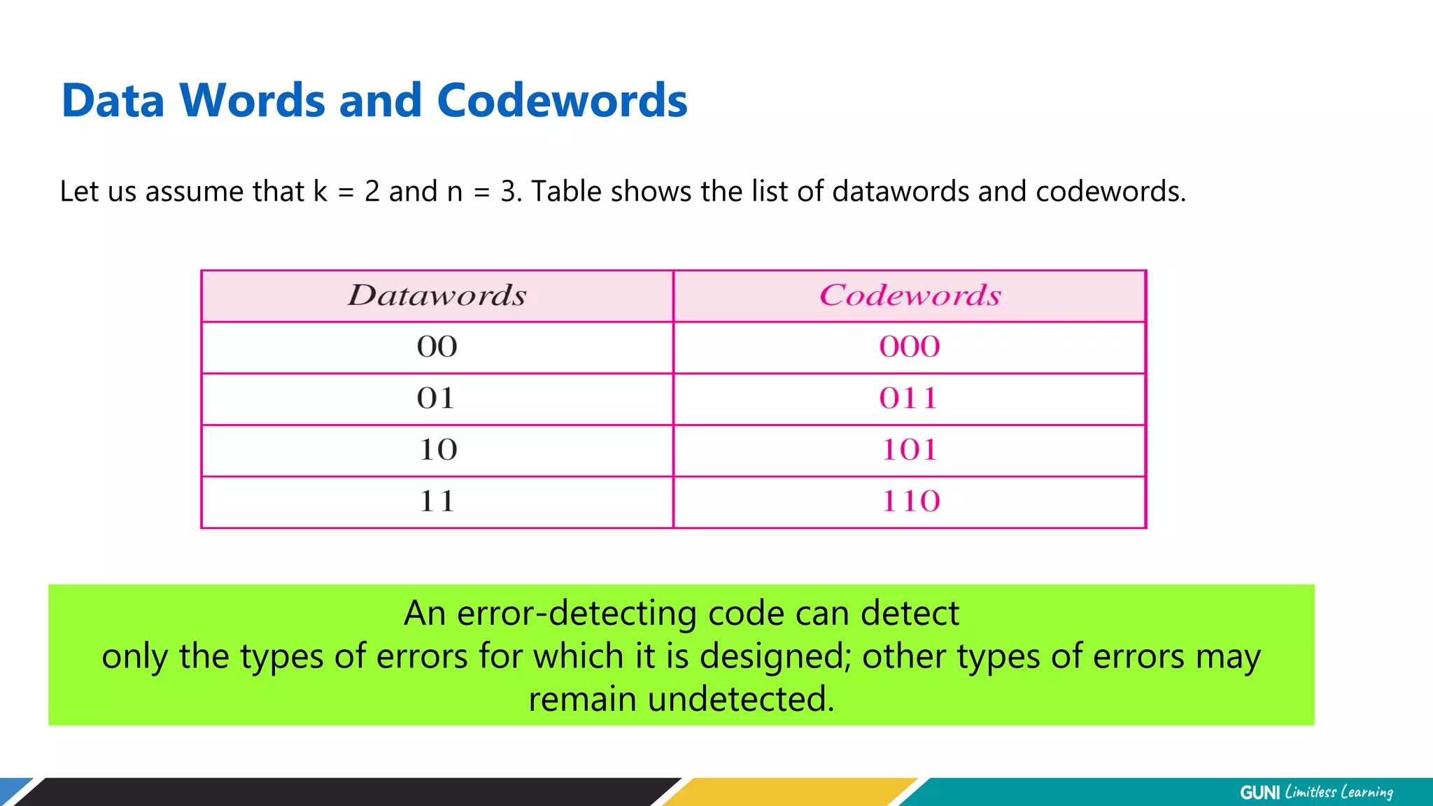
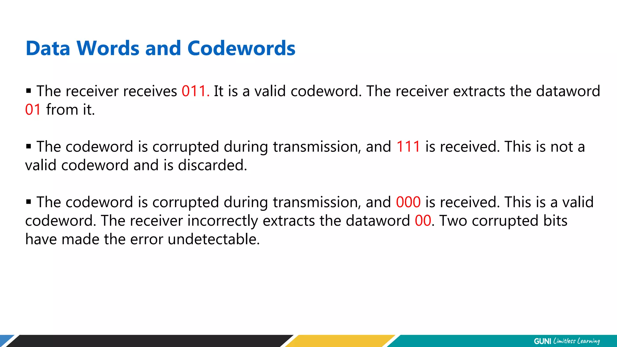
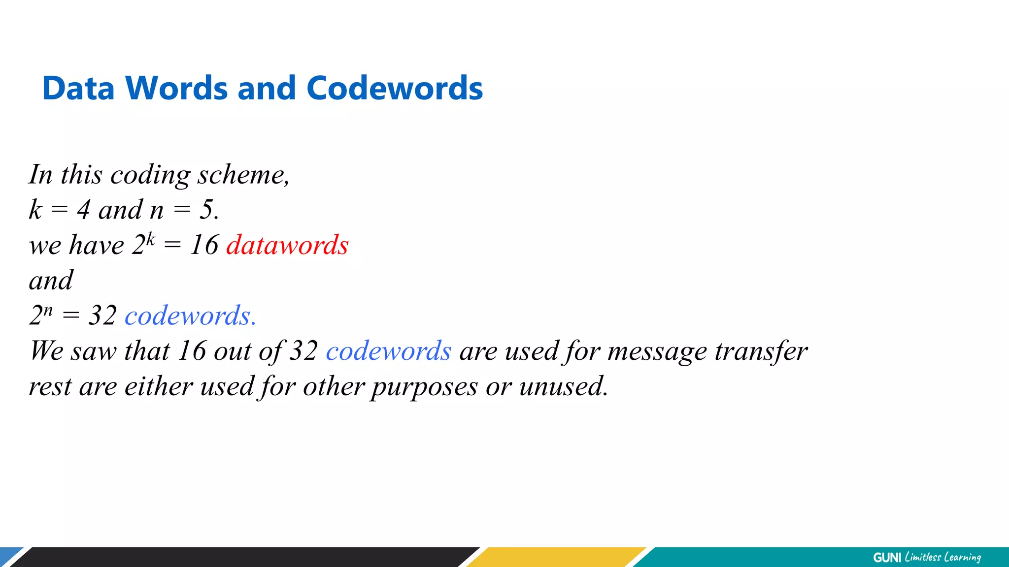
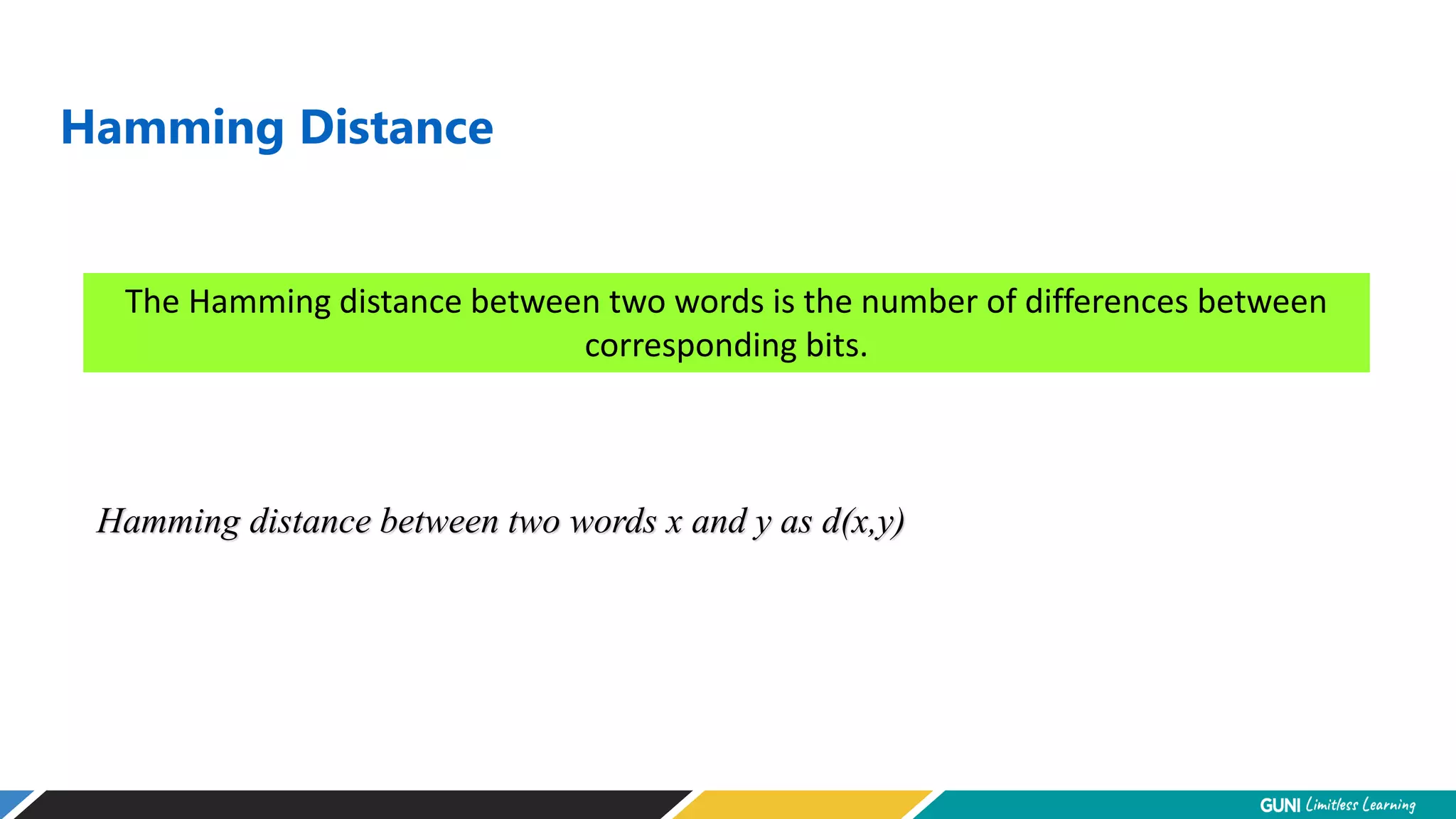
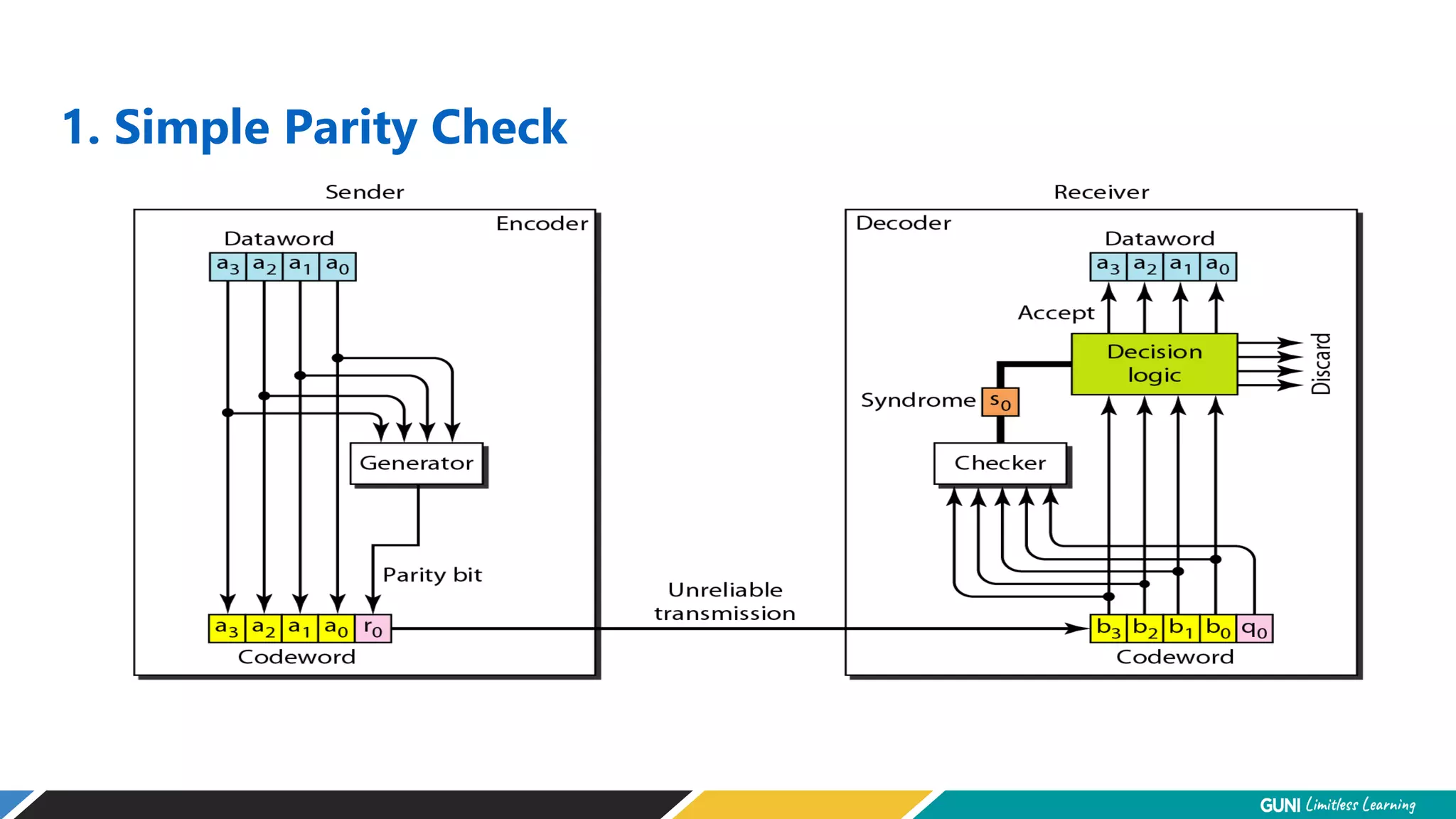
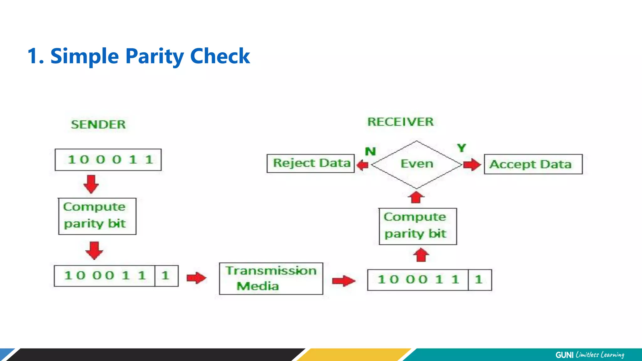
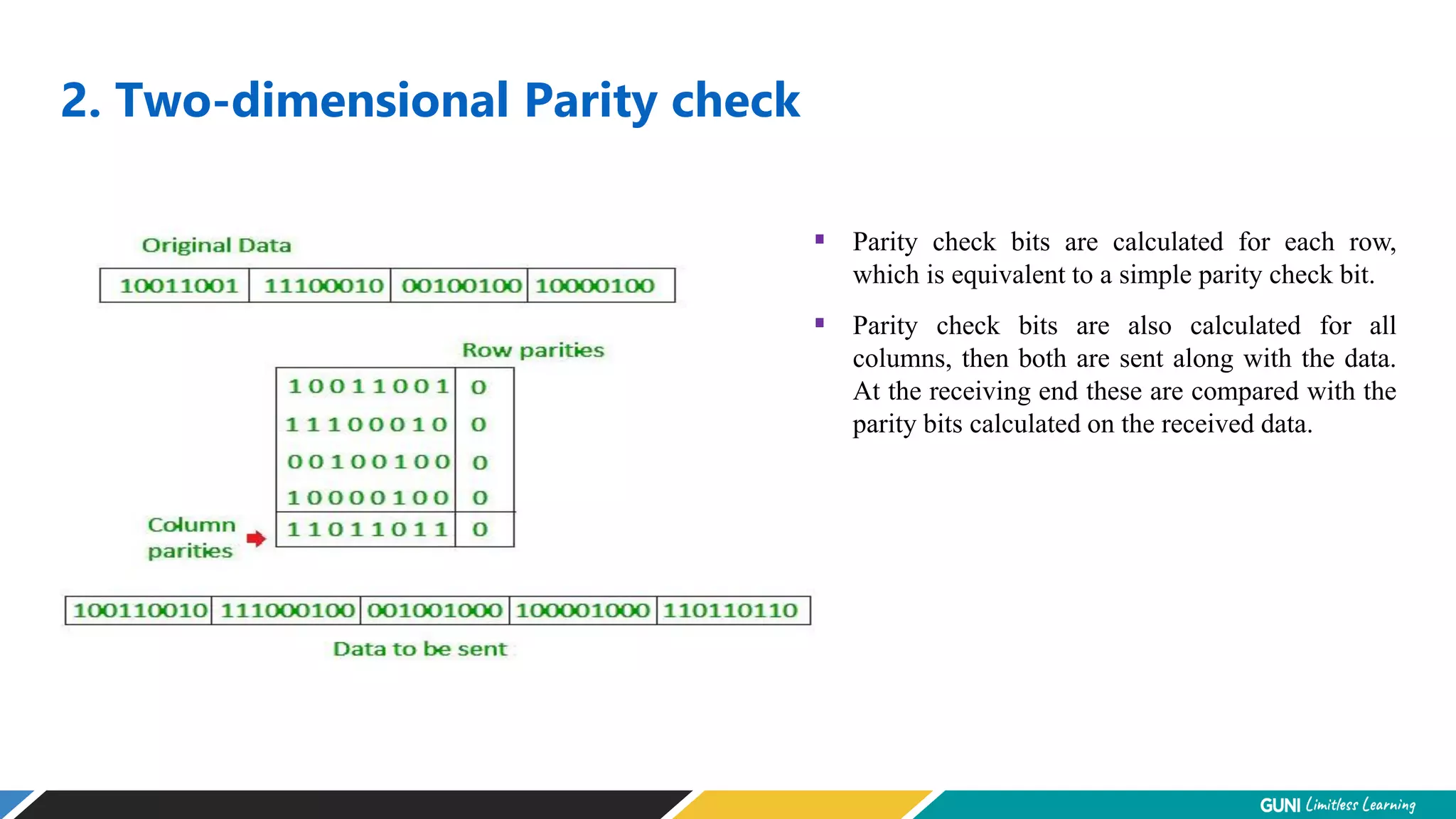
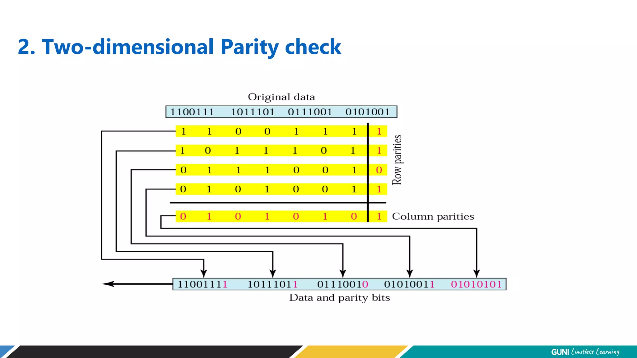
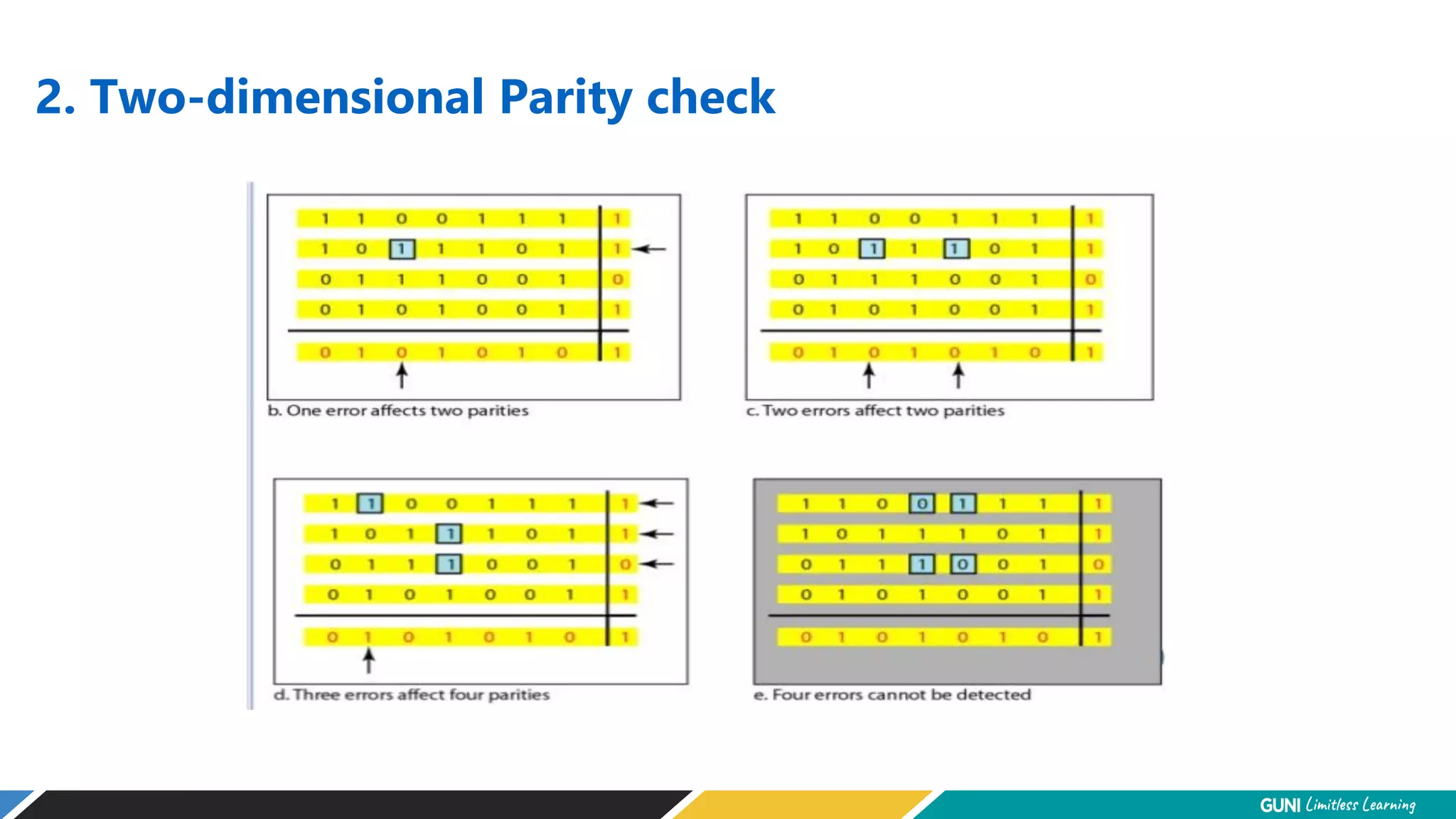
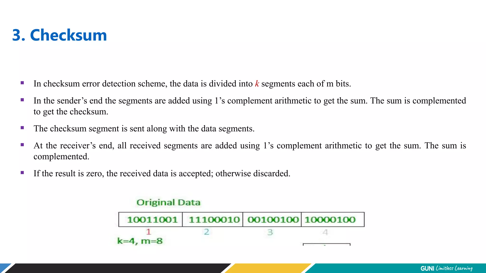
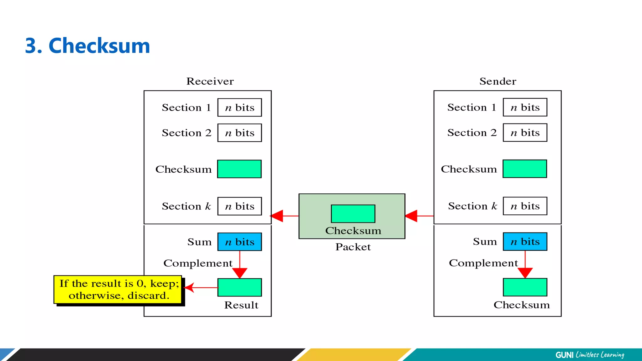
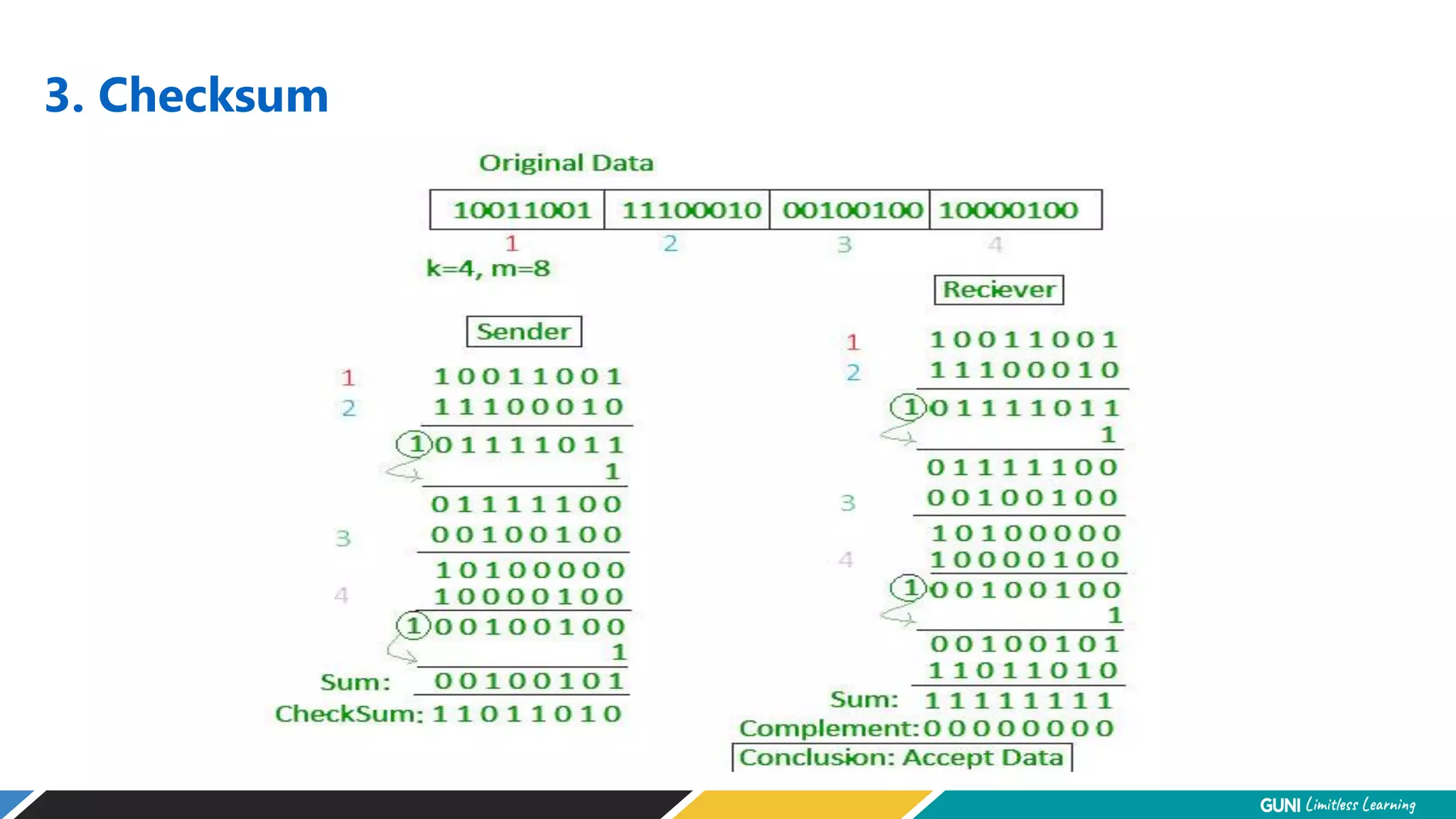
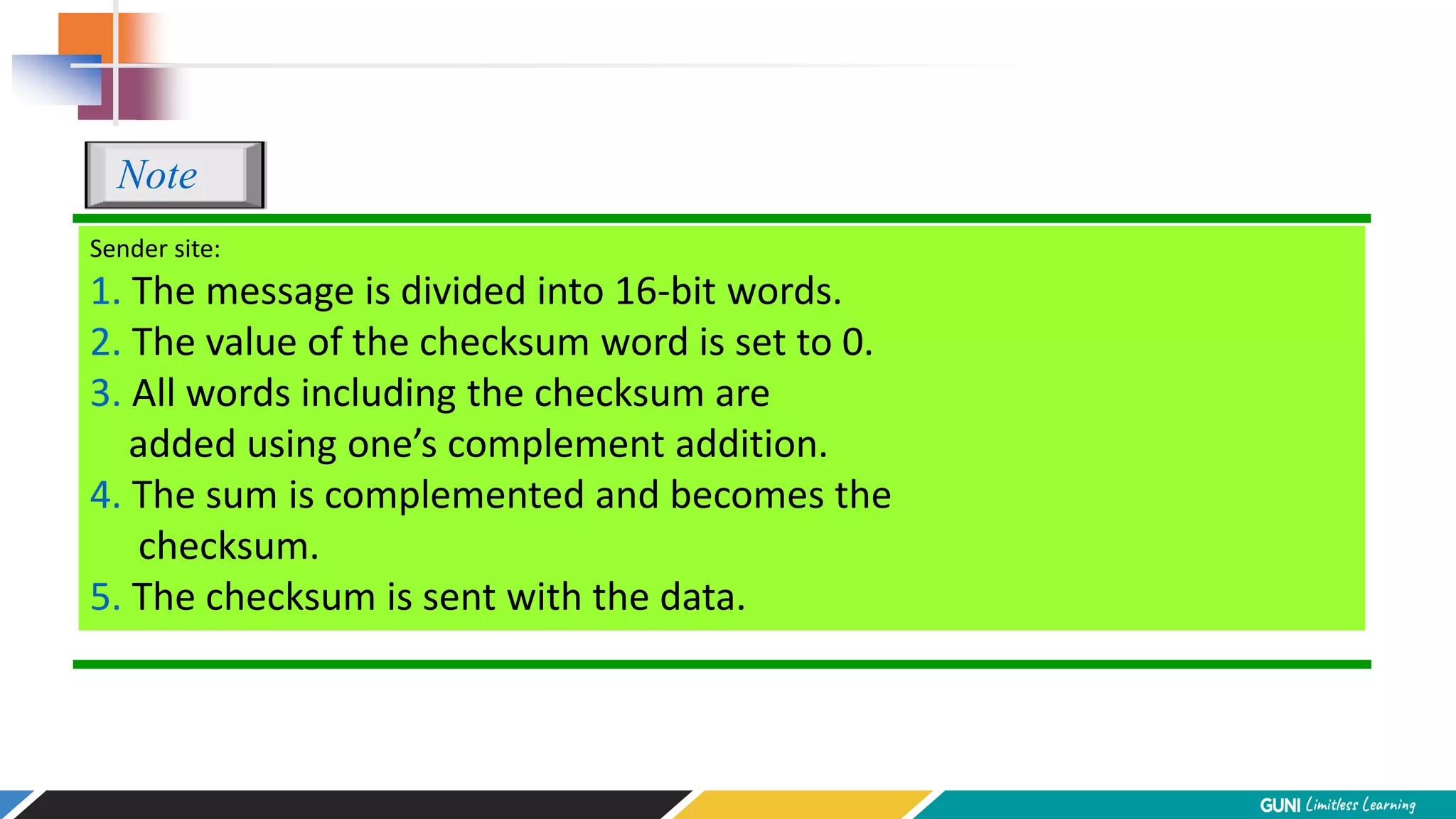
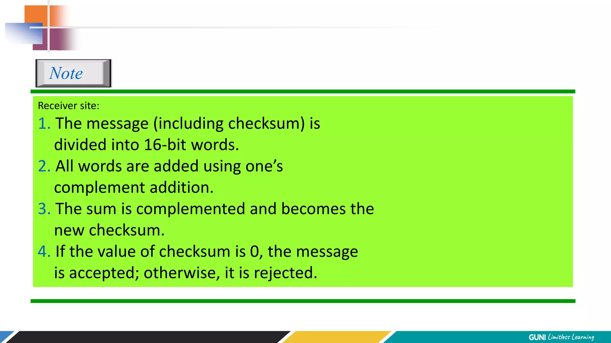
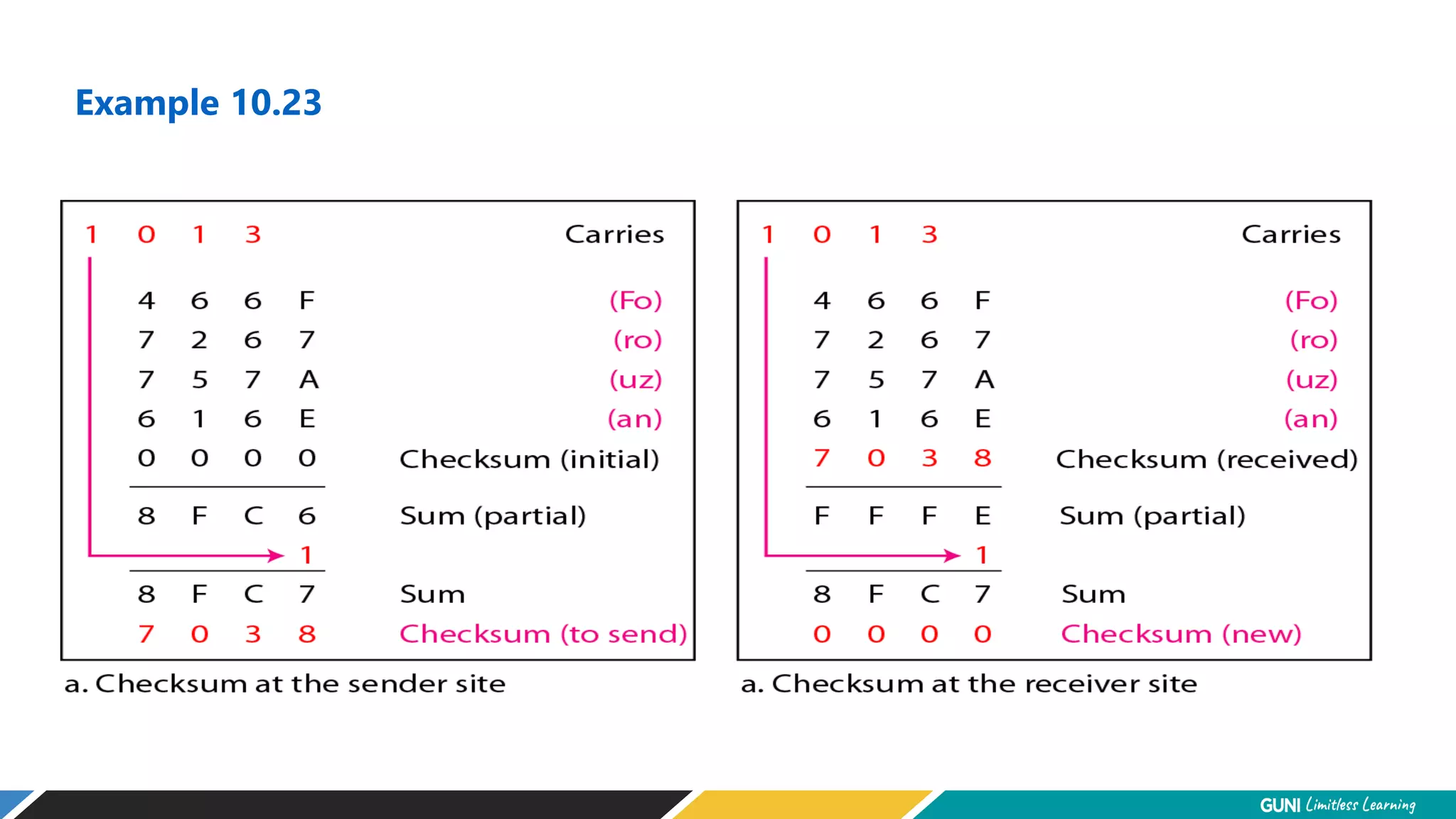
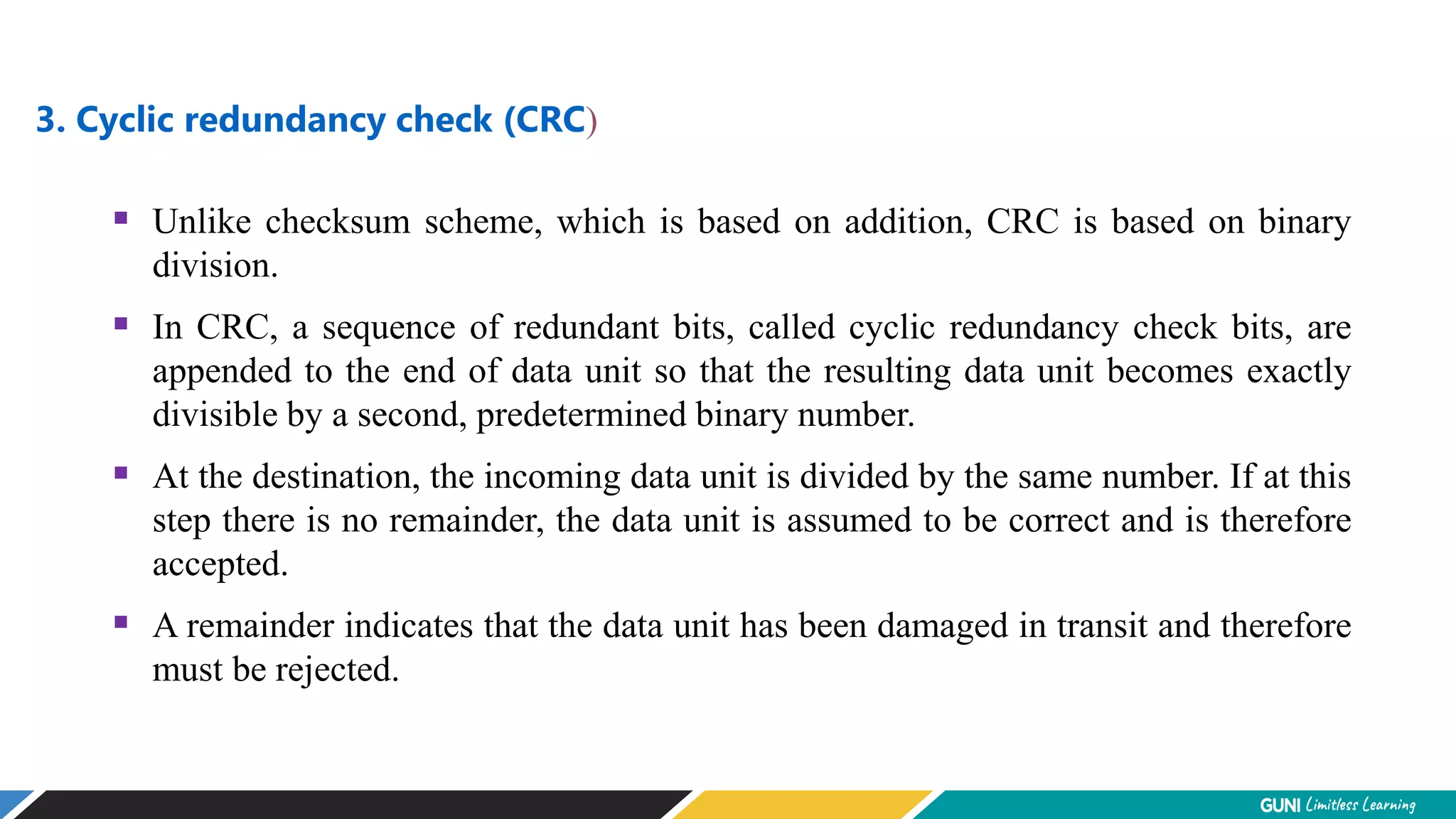
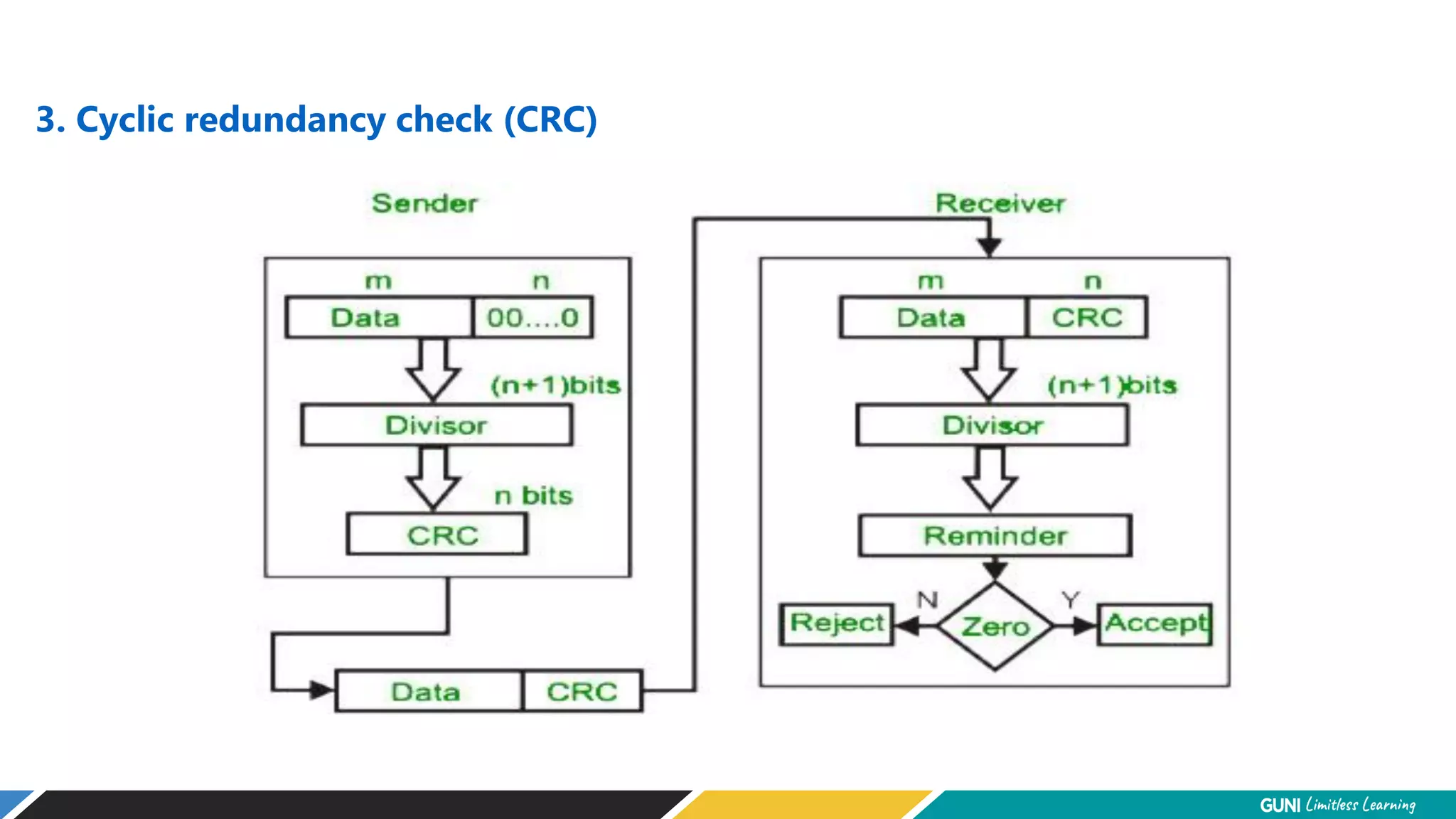
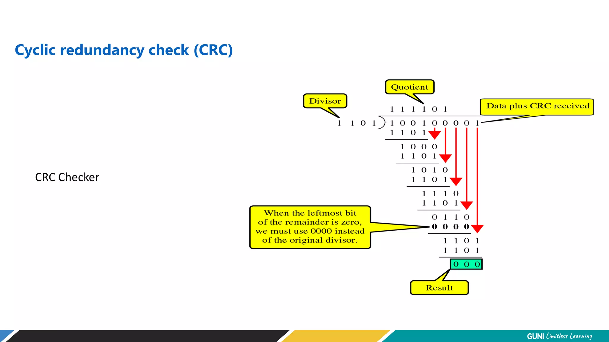
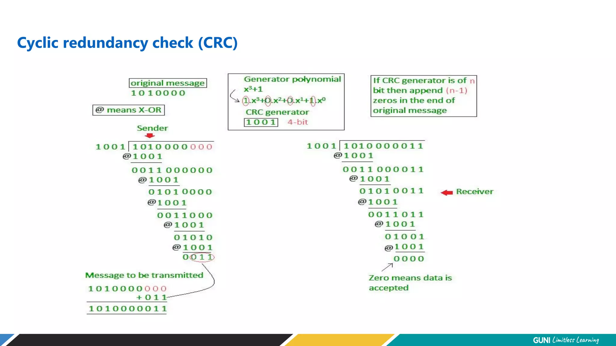
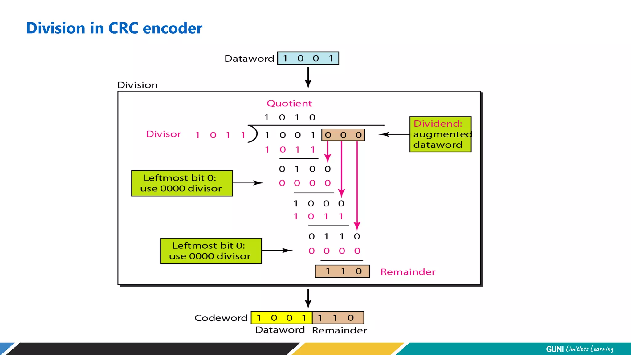
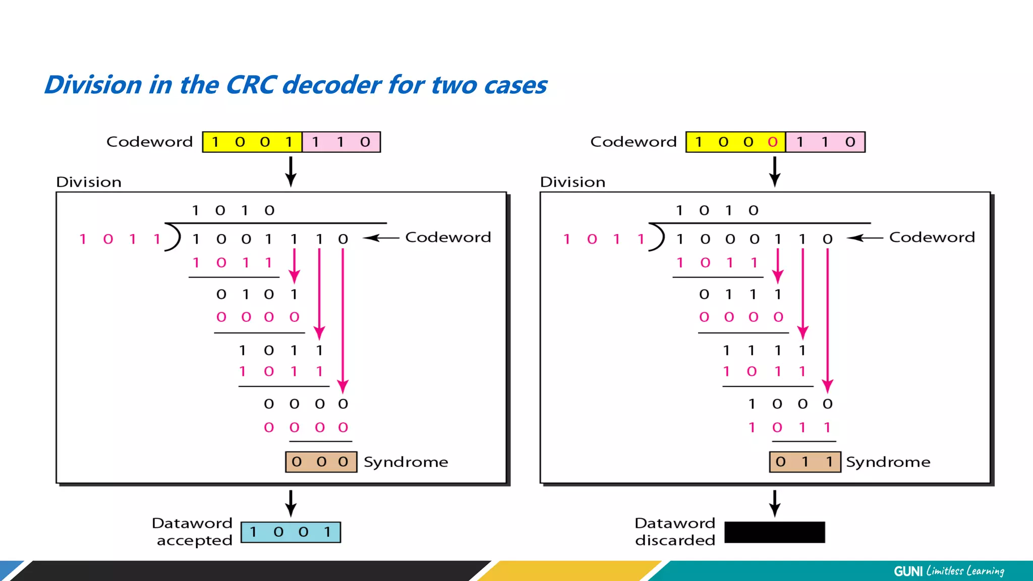
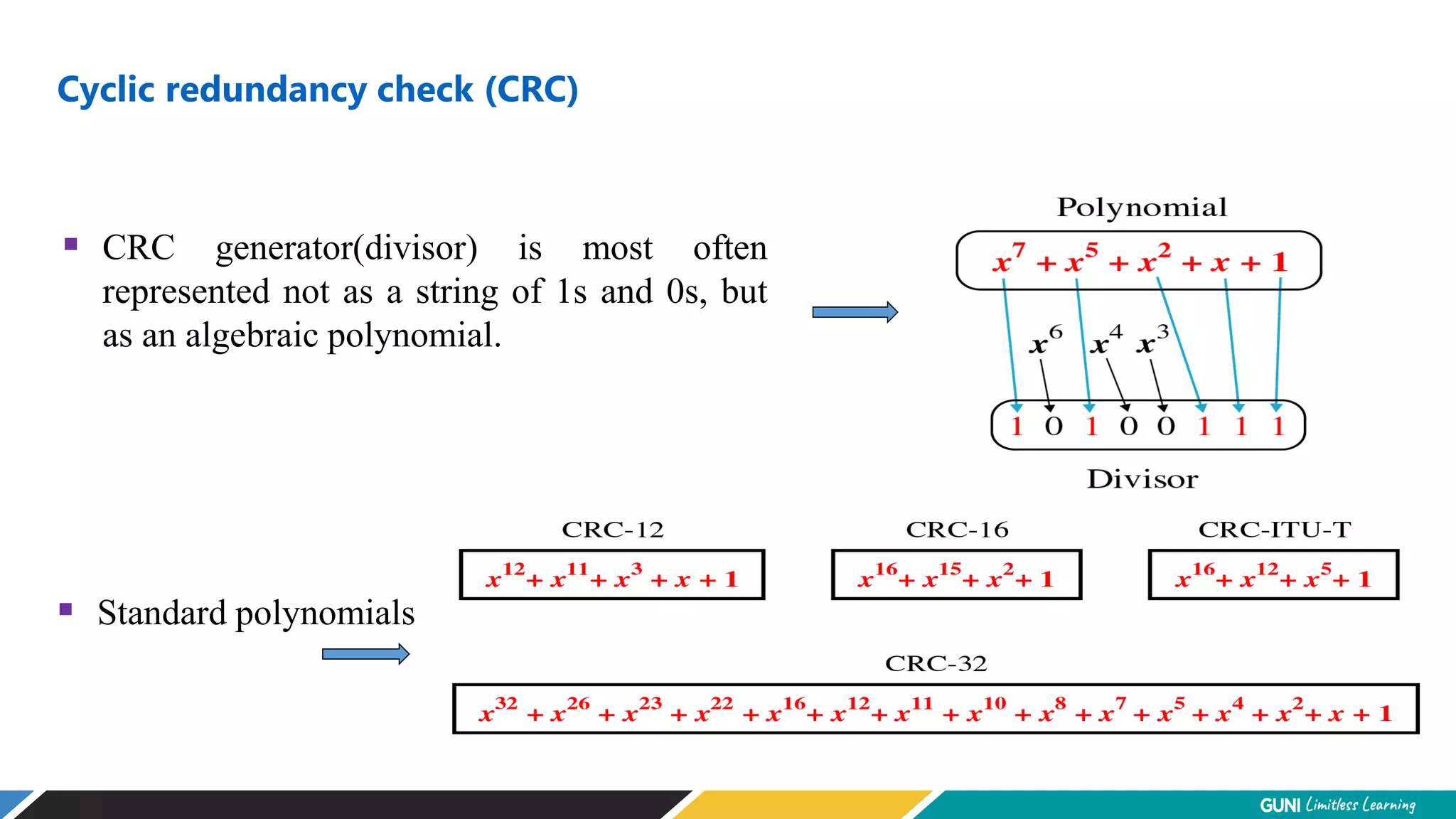
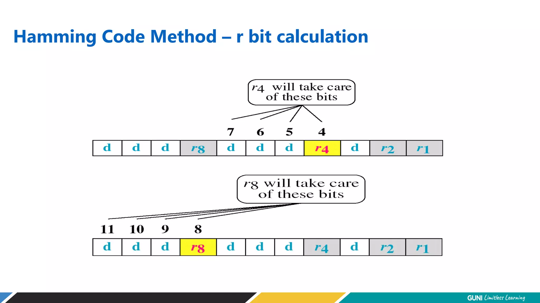
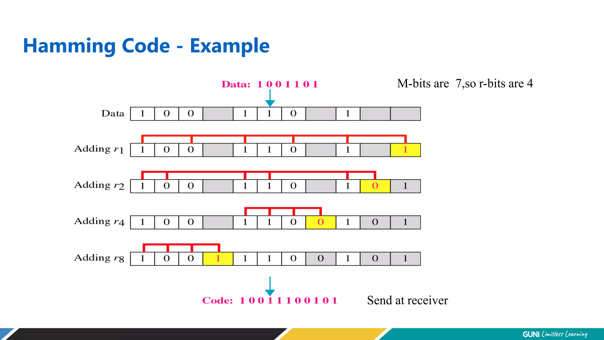
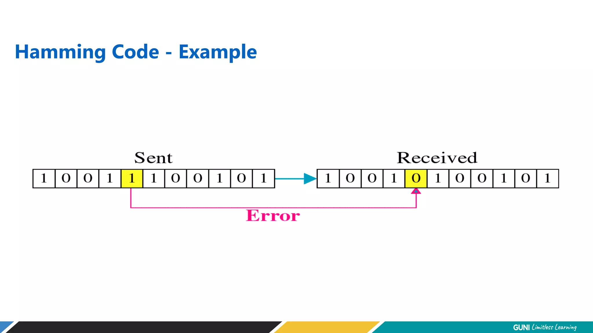
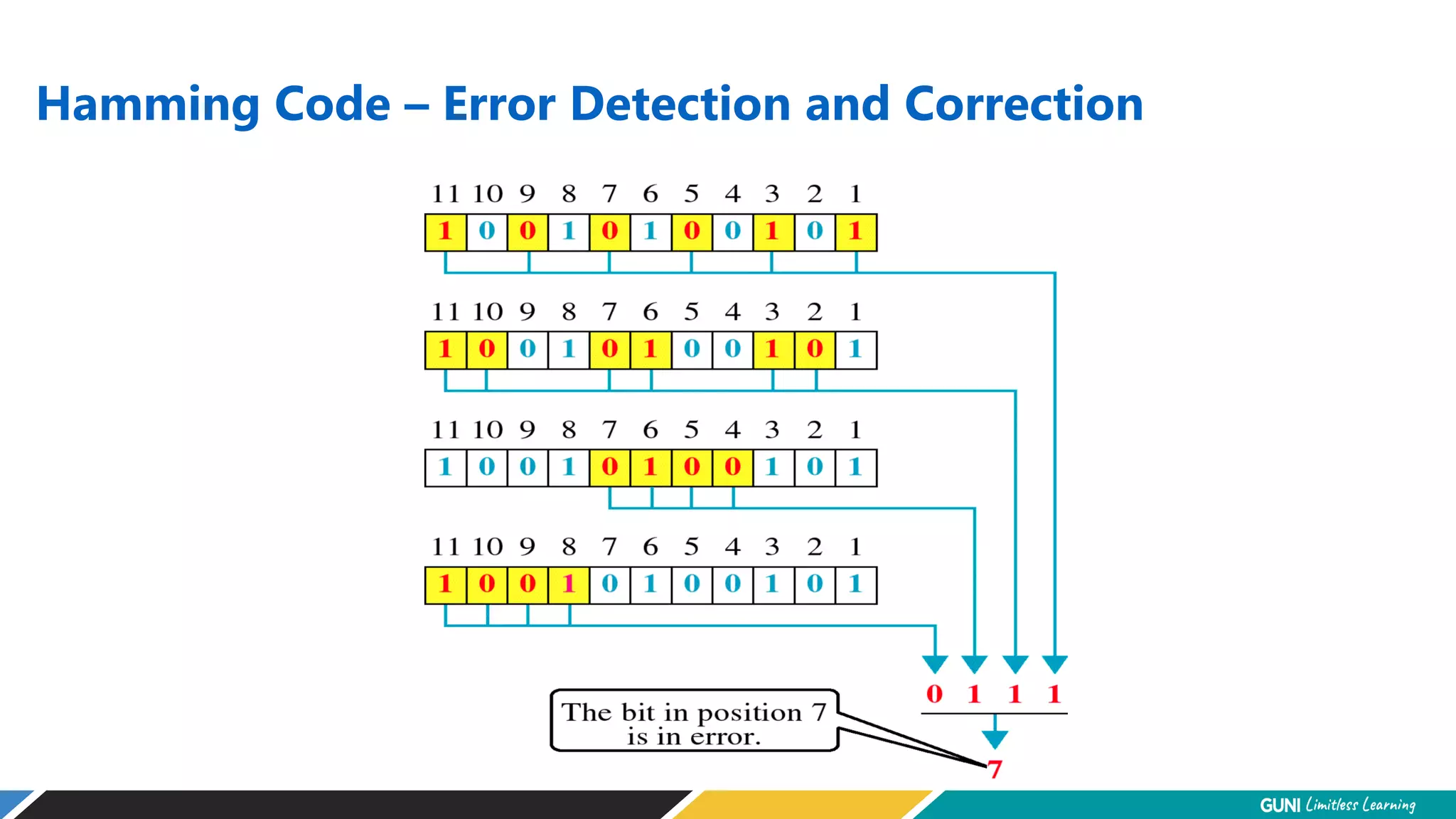
2. Error Detection and Correction
Networks must be able to transfer data from one device to another
with complete accuracy.
Data can be corrupted during transmission.
For reliable communication, errors must be detected and corrected.
Error detection and correction are implemented either at the data
link layer or the transport layer of the OSI model.
3. Error detection and correction
Error detection:
errors caused by signal attenuation, noise.
receiver detects presence of errors:
signals sender for retransmission or drops frame
Error correction:
receiver identifies and corrects bit error(s) without resorting to
retransmission
5. Single-bit error
Single bit errors are the least likely type of errors in serial data transmission
because the noise must have a very short duration which is very rare.
However this kind of errors can happen in parallel transmission.
If data is sent at rate = 1Kbps then a noise of 1/100 sec can affect 10 bits.(1/100*1000)
If same data is sent at rate = 1Mbps then a noise of 1/100 sec can affect 10,000 bits.(1/100*106)
6. Burst error
The term burst error means that two or more bits in the data unit have changed from 1 to 0 or from 0
to 1.
Burst errors does not necessarily mean that the errors occur in consecutive bits, the length of the burst
is measured from the first corrupted bit to the last corrupted bit. Some bits in between may not have
been corrupted.
8. Redundancy
Error detection uses the concept of redundancy, which means adding extra bits for detecting errors
at the destination.
Error detection means to decide whether the received data is correct or not without having a copy of
the original message.
10. Forward error correction vs Retransmission
Forward error correction is process in which the receiver tries to guess
the message by using redundant bits
Used when number of errors is small
Retransmission is technique in which the receiver detects the occurrence
of an error and asks the sender to resend the message
11. Coding
Redundancy is achieved through various coding schemes.
The sender adds redundant bits through a process that creates a relationship between
the redundant bits and the actual data bits.
The receiver checks the relationships between the two sets of bits to detect or correct
the errors. The ratio of redundant bits to the data bits and the robust ness of the
process are important factors in any coding scheme.
(1) Block Coding
(2) Linear Block Coding
13. Block Coding
In block coding, we divide our message into blocks, each of k bits, called
datawords. We add r redundant bits to each block to make the length n = k + r.
The resulting n-bit blocks are called codewords.
14. Data Words and Codewords
An error-detecting code can detect
only the types of errors for which it is designed; other types of errors may
remain undetected.
Let us assume that k = 2 and n = 3. Table shows the list of datawords and codewords.
15. Data Words and Codewords
The receiver receives 011. It is a valid codeword. The receiver extracts the dataword
01 from it.
The codeword is corrupted during transmission, and 111 is received. This is not a
valid codeword and is discarded.
The codeword is corrupted during transmission, and 000 is received. This is a valid
codeword. The receiver incorrectly extracts the dataword 00. Two corrupted bits
have made the error undetectable.
16. Data Words and Codewords
In this coding scheme,
k = 4 and n = 5.
we have 2k = 16 datawords
and
2n = 32 codewords.
We saw that 16 out of 32 codewords are used for message transfer
rest are either used for other purposes or unused.
17. Hamming Distance
The Hamming distance between two words is the number of differences between
corresponding bits.
Hamming distance between two words x and y as d(x,y)
18. Let us find the Hamming distance between two pairs of words.
1. The Hamming distance d(000, 011) is 2 because
Example 10.4
2. The Hamming distance d(10101, 11110) is 3 because
19. The minimum Hamming distance is the smallest Hamming distance between
all possible pairs in a set of words.
Note
20. Find the minimum Hamming distance of the coding scheme in Table 10.1.
Solution
We first find all Hamming distances.
Minimum hamming distance
The dmin in this case is 2.
21. Find the minimum Hamming distance of the coding scheme in Table 10.2.
Solution
We first find all the Hamming distances.
The dmin in this case is 3.
Example 10.6
22. Parameters for coding scheme
codeword size n
dataword size k
Minimum hamming distance dmin
Coding scheme C is written as C(n,k)
23. Hamming distance and Error
Find minimum distance in code if we want to be able to detect up to S errors
If our code is to detect up to S errors, the minimum distance between the valid codes must be S + 1
To guarantee the detection of up to s errors in all cases, the minimum
Hamming distance in a block
code must be dmin = s + 1.
24. Hamming distance and Error
If sent codewords X is at the center of a circle with redius S.
All received codewords that are created by 1 to S errors are points inside the circle or on the perimeter of
the circle.
All valid code words must be outside the circle
25. Error Detection Techniques ( Linear Block Codes)
Basic approach used for error detection is the use of redundancy bits, where additional
bits are added to facilitate detection of errors.
Some popular techniques for error detection are:
1. Simple Parity check
2. Two-dimensional Parity check
3. Checksum
4. Cyclic redundancy check
26. 1. Simple Parity Check
A simple parity-check code is a
single-bit error-detecting
code in which
n = k + 1 with dmin = 2.
Blocks of data from the source are subjected to a check bit or parity bit generator form, where a parity of :
1 is added to the block if it contains odd number of 1’s, and
0 is added if it contains even number of 1’s
This scheme makes the total number of 1’s even, that is why it is called even parity
checking.
30. Assume the sender sends the dataword 1011. The codeword created from this dataword is 10111, which is
sent to the receiver. We examine five cases:
No error occurs; the received codeword is 10111. The syndrome is 0. The dataword 1011 is created.
One single-bit error changes a1 . The received codeword is 10011. The syndrome is 1. No dataword is
created.
One single-bit error changes r0 . The received codeword is 10110. The syndrome is 1. No dataword is
created.
An error changes r0 and a second error changes a3 . The received codeword is 00110. The syndrome is 0.
The dataword 0011 is created at the receiver. Note that here the dataword is wrongly created due to the
syndrome value.
Three bits—a3, a2, and a1—are changed by errors. The received codeword is 01011. The syndrome is 1.
The dataword is not created. This shows that the simple parity check, guaranteed to detect one single error,
can also find any odd number of errors.
Example 10.12
31. 2. Two-dimensional Parity check
Parity check bits are calculated for each row,
which is equivalent to a simple parity check bit.
Parity check bits are also calculated for all
columns, then both are sent along with the data.
At the receiving end these are compared with the
parity bits calculated on the received data.
34. 3. Checksum
In checksum error detection scheme, the data is divided into k segments each of m bits.
In the sender’s end the segments are added using 1’s complement arithmetic to get the sum. The sum is complemented
to get the checksum.
The checksum segment is sent along with the data segments.
At the receiver’s end, all received segments are added using 1’s complement arithmetic to get the sum. The sum is
complemented.
If the result is zero, the received data is accepted; otherwise discarded.
37. • Suppose our data is a list of five 4-bit numbers that we want to send to a destination. In
addition to sending these numbers, we send the sum of the numbers.
• For example, if the set of numbers is (7, 11, 12, 0, 6), we send (7, 11, 12, 0, 6, 36), where
36 is the sum of the original numbers.
• The receiver adds the five numbers and compares the result with the sum. If the two are
the same, the receiver assumes no error, accepts the five numbers, and discards the sum.
• Otherwise, there is an error somewhere and the data are not accepted.
Example 10.18
38. We can make the job of the receiver easier if we send the negative (complement)
of the sum, called the checksum. In this case, we send (7, 11, 12, 0, 6, −36). The
receiver can add all the numbers received (including the checksum). If the
result is 0, it assumes no error; otherwise, there is an error.
Example 10.19
39. How can we represent the number 21 in one’s complement arithmetic using
only four bits?
Solution
The number 21 in binary is 10101 (it needs five bits). We can wrap the leftmost
bit and add it to the four rightmost bits. We have (0101 + 1) = 0110 or 6.
Example 10.20
40. How can we represent the number −6 in one’s complement arithmetic using
only four bits?
Solution
In one’s complement arithmetic, the negative or complement of a number is
found by inverting all bits. Positive 6 is 0110; negative 6 is 1001. If we consider
only unsigned numbers, this is 9. In other words, the complement of 6 is 9.
Another way to find the complement of a number in one’s complement
arithmetic is to subtract the number from 2n − 1 (16 − 1 in this case).
Example 10.21
41. The receiver follows the same procedure as the sender. It adds all data items
(including the checksum); the result is 45. The sum is wrapped and becomes
15. The wrapped sum is complemented and becomes 0. Since the value of the
checksum is 0, this means that the data is not corrupted. The receiver drops
the checksum and keeps the other data items. If the checksum is not zero, the
entire packet is dropped.
Example 10.22 (continued)
43. Sender site:
1. The message is divided into 16-bit words.
2. The value of the checksum word is set to 0.
3. All words including the checksum are
added using one’s complement addition.
4. The sum is complemented and becomes the
checksum.
5. The checksum is sent with the data.
Note
44. Receiver site:
1. The message (including checksum) is
divided into 16-bit words.
2. All words are added using one’s
complement addition.
3. The sum is complemented and becomes the
new checksum.
4. If the value of checksum is 0, the message
is accepted; otherwise, it is rejected.
Note
46. Performance of Checksum
The checksum detects all errors involving an odd number of bits.
It detects most errors involving an even number of bits.
If one or more bits of a segment are damaged and the corresponding bit or bits of
opposite value in a second segment are also damaged, the sums of those columns will
not change and the receiver will not detect a problem.
47. 3. Cyclic redundancy check (CRC)
Unlike checksum scheme, which is based on addition, CRC is based on binary
division.
In CRC, a sequence of redundant bits, called cyclic redundancy check bits, are
appended to the end of data unit so that the resulting data unit becomes exactly
divisible by a second, predetermined binary number.
At the destination, the incoming data unit is divided by the same number. If at this
step there is no remainder, the data unit is assumed to be correct and is therefore
accepted.
A remainder indicates that the data unit has been damaged in transit and therefore
must be rejected.
55. Cyclic redundancy check (CRC)
CRC generator(divisor) is most often
represented not as a string of 1s and 0s, but
as an algebraic polynomial.
Standard polynomials
59. The divisor in a cyclic code is normally called the generator polynomial
or simply the generator.
Note
60. In a cyclic code,
If s(x) ≠ 0, one or more bits is corrupted.
If s(x) = 0, either
a. No bit is corrupted. or
b. Some bits are corrupted, but the
decoder failed to detect them.
Note
61. In a cyclic code, those e(x) errors that are divisible by g(x) are not caught.
Note
62. If the generator has more than one term and the coefficient of x0 is 1,
all single errors can be caught.
Note
63. The receiver received 10011101101 from sender. The original
message is transmitted using CRC polynomial X3 + 1 to protect
from errors. Check whether message bits are corrupted during
transmission or not?
64. Find the suitability of the following generators in relation to burst errors of
different lengths.
a. x6 + 1 b. x18 + x7 + x + 1 c. x32 + x23 + x7 + 1
Solution
a. This generator can detect all burst errors with a length
less than or equal to 6 bits; 3 out of 100 burst errors
with length 7 will slip by; 16 out of 1000 burst errors of
length 8 or more will slip by.
Example 10.17
65. b. This generator can detect all burst errors with a length less than or equal to
18 bits; 8 out of 1 million burst errors with length 19 will slip by; 4 out of 1
million burst errors of length 20 or more will slip by.
c. This generator can detect all burst errors with a length less than or equal to
32 bits; 5 out of 10 billion burst errors with length 33 will slip by; 3 out of 10
billion burst errors of length 34 or more will slip by.
Example 10.17 (continued)
66. A good polynomial generator needs to have the following characteristics:
1. It should have at least two terms.
2. The coefficient of the term x0 should
be 1.
3. It should not divide xt + 1, for t
between 2 and n − 1.
4. It should have the factor x + 1.
Note
67. Error Correction
To correct an error, the receiver reverses the value of the altered bit. To do so, it
must know which bit is in error.
Single – bit Error correction used parity bit
The secret of error correction is to locate the invalid bit or bits
68. Error Correction - Calculation of Redundancy Bits
To calculate the number of redundancy bits (R) required to correct a given number of data bit (M)
69. Error Correction - Calculation of Redundancy Bits
To calculate the number of redundancy bits (R) required to correct a given number of data bit (M)
If the total number of bits in a transmittable unit is m+r, then r must be able to indicate at least
m+r+1 different states
2r m + r + 1
For value of m is 7(ASCII), the smallest r value that can satisfy this equation is 4
24 7 + 4 + 1
70. Relationship between data bits and Redundancy bits
Number of Data Bits
(m)
Number of Redundancy Bits
(r)
Total Bits
(m+r)
1
2
3
4
5
6
7
2
3
3
3
4
4
4
3
5
6
7
9
10
11
71. Error Correction - Hamming Code Method
Develop by R.W. Hamming
positions of redundancy bits in Hamming code
72. Error Correction - Hamming Code Method
each r bit is calculating by using
combination of data bits
r1 = bits 1, 3, 5, 7, 9, 11
r2 = bits 2, 3, 6, 7, 10, 11
r4 = bits 4, 5, 6, 7
r8 = bits 8, 9, 10, 11