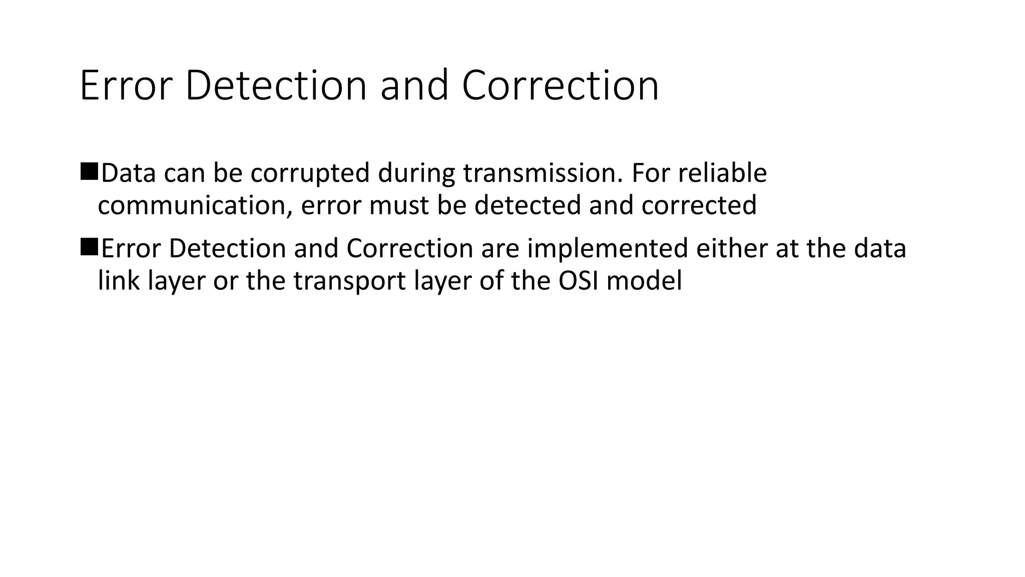
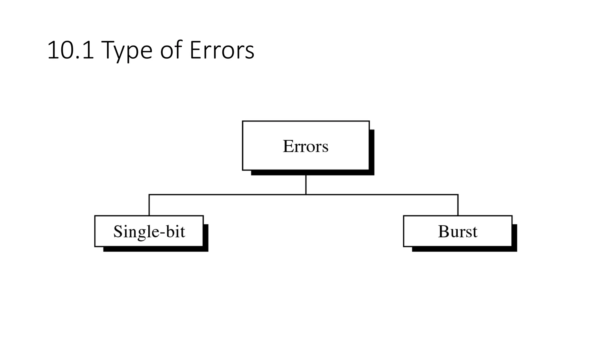
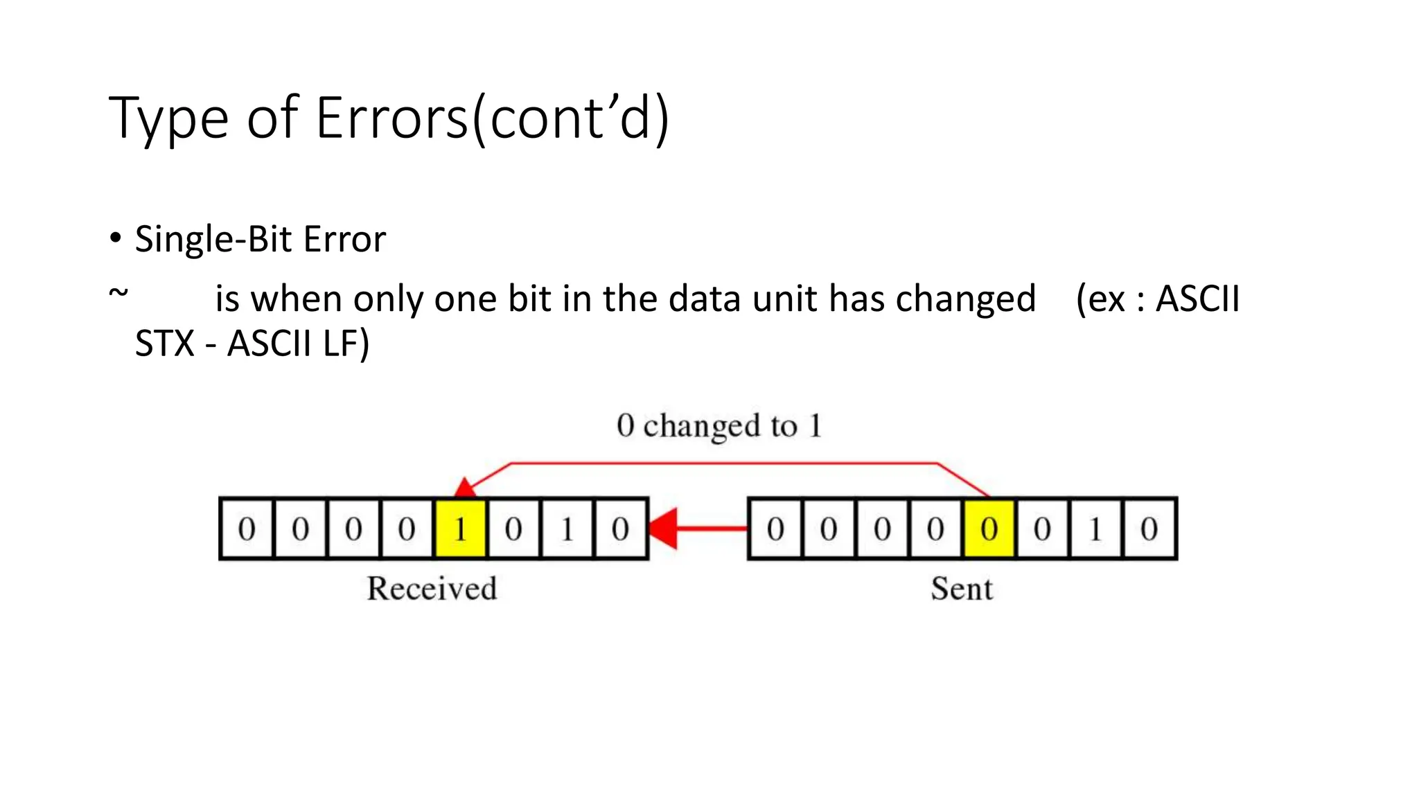
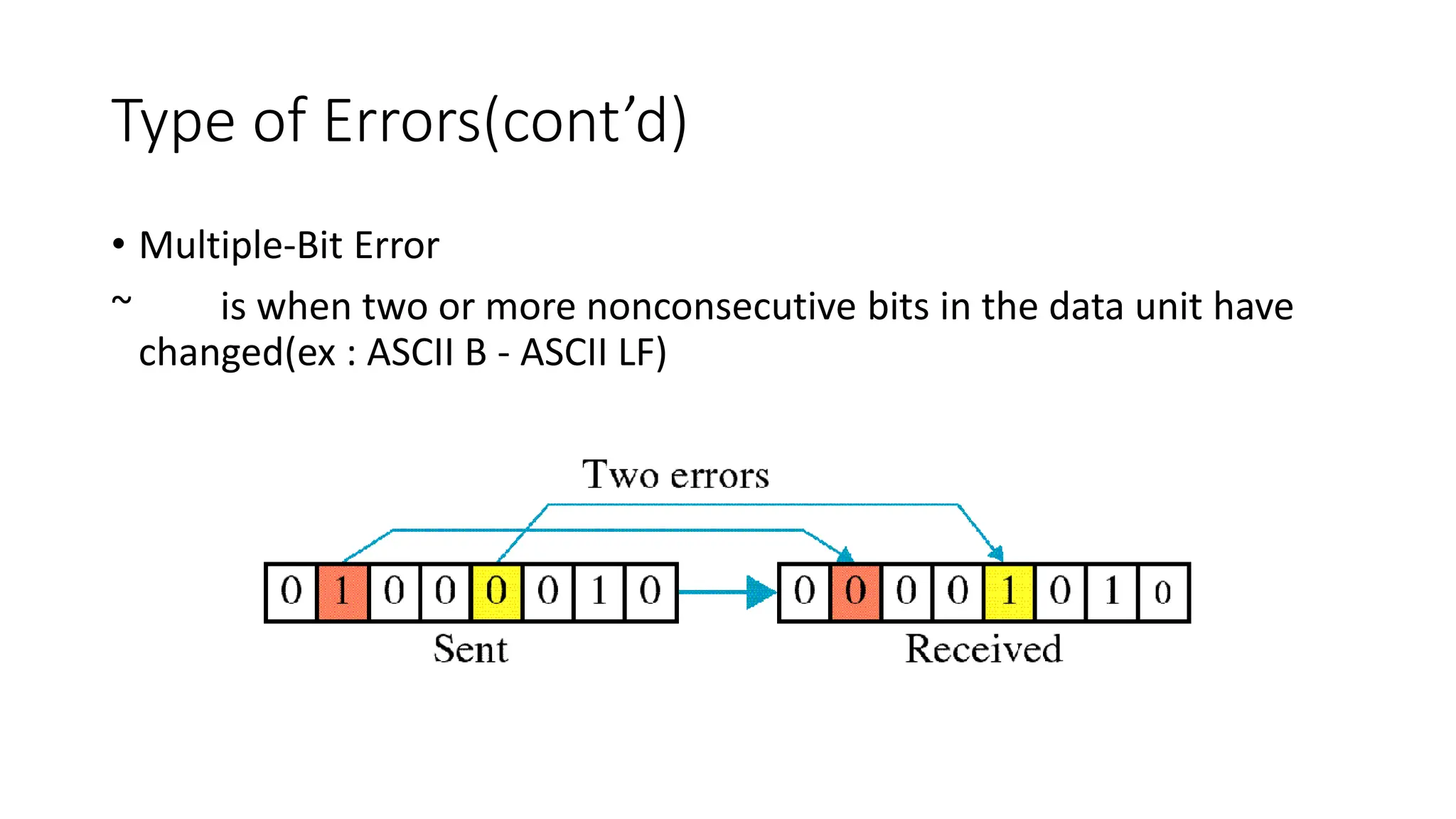
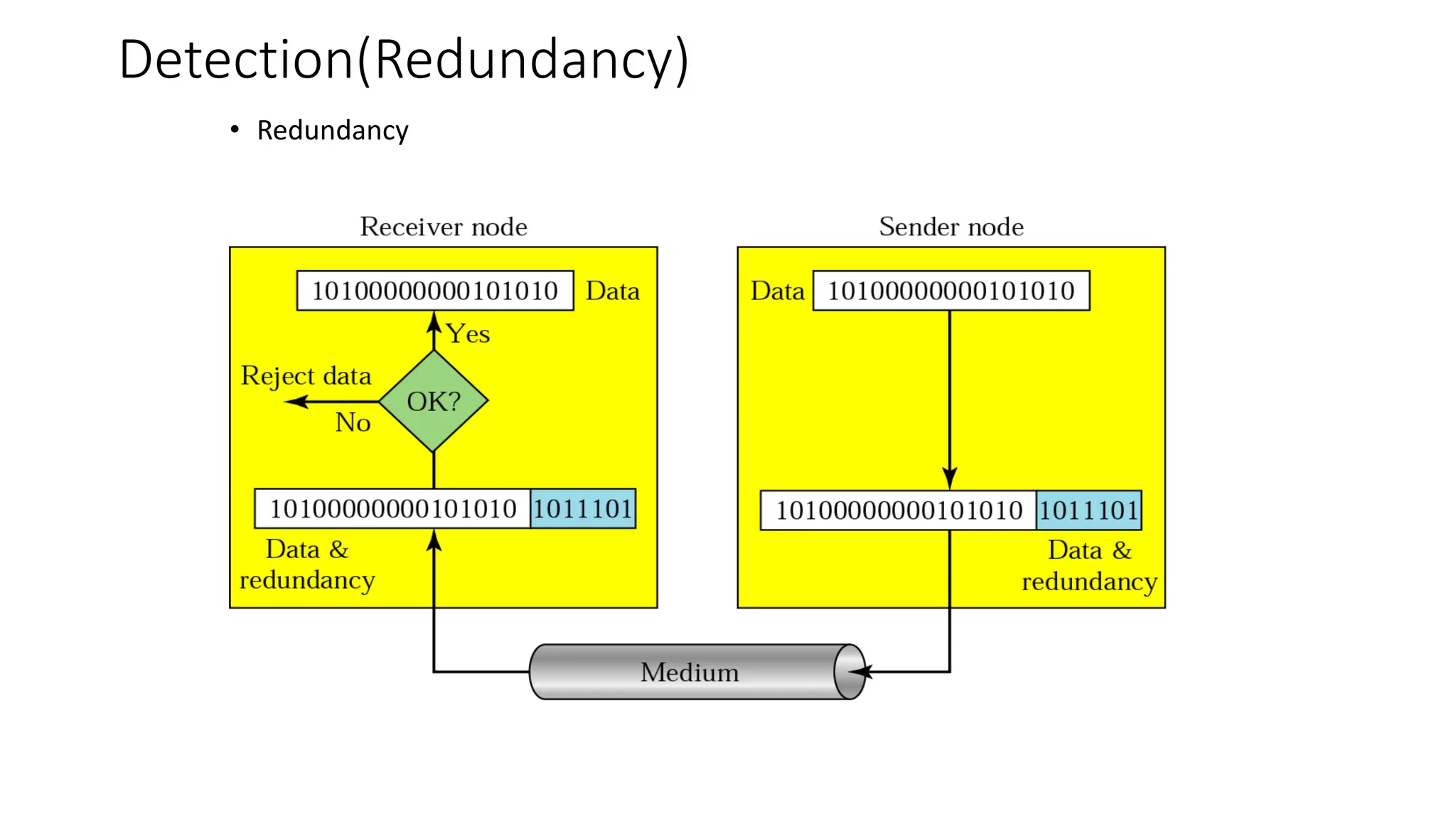
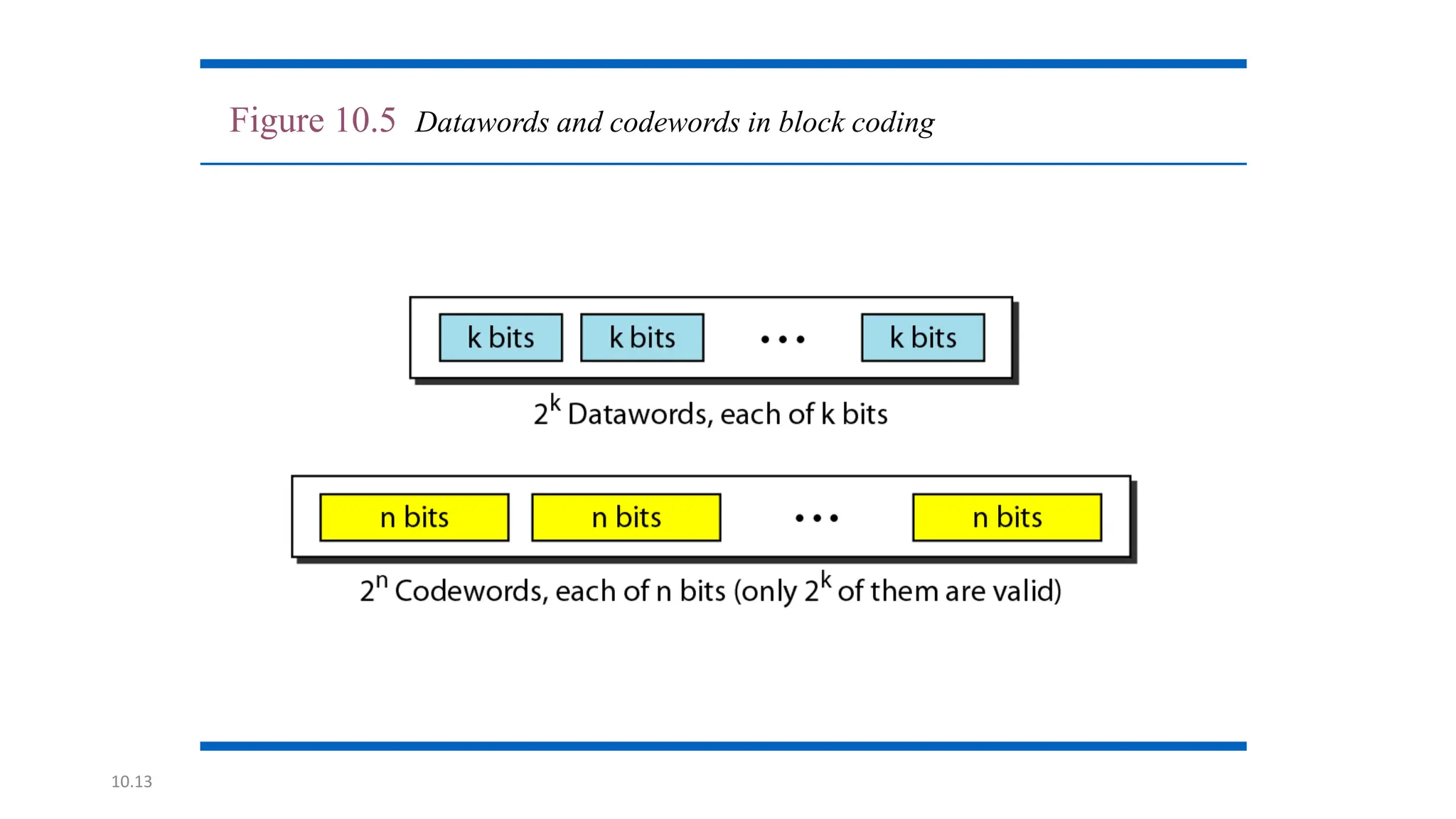
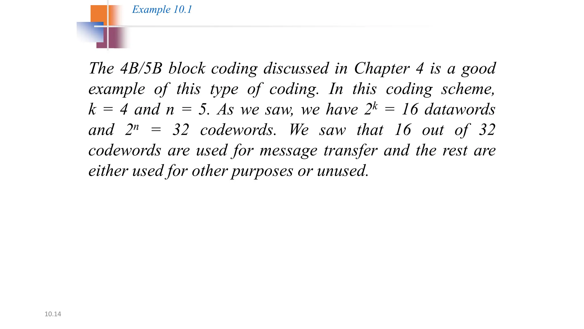
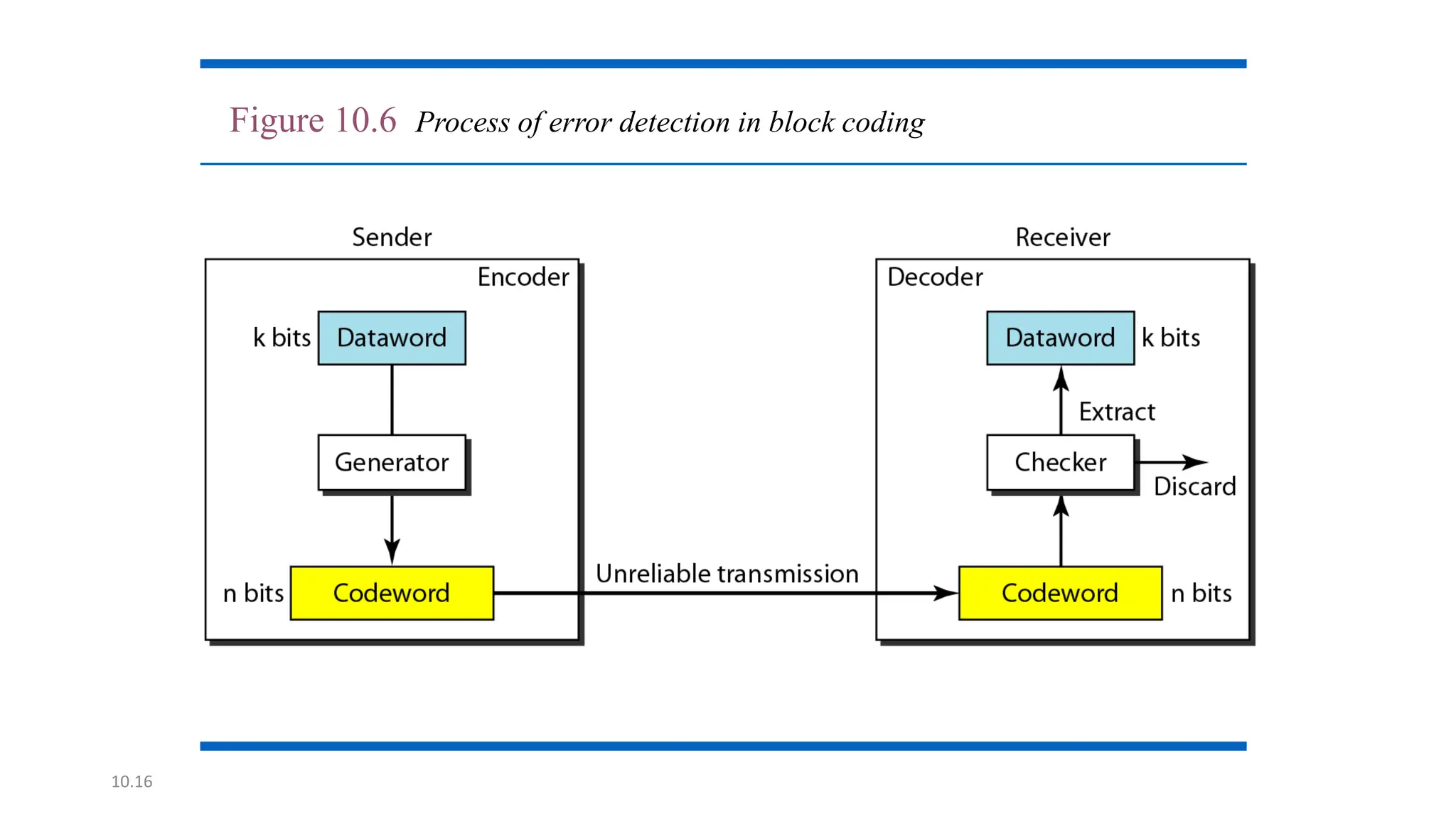
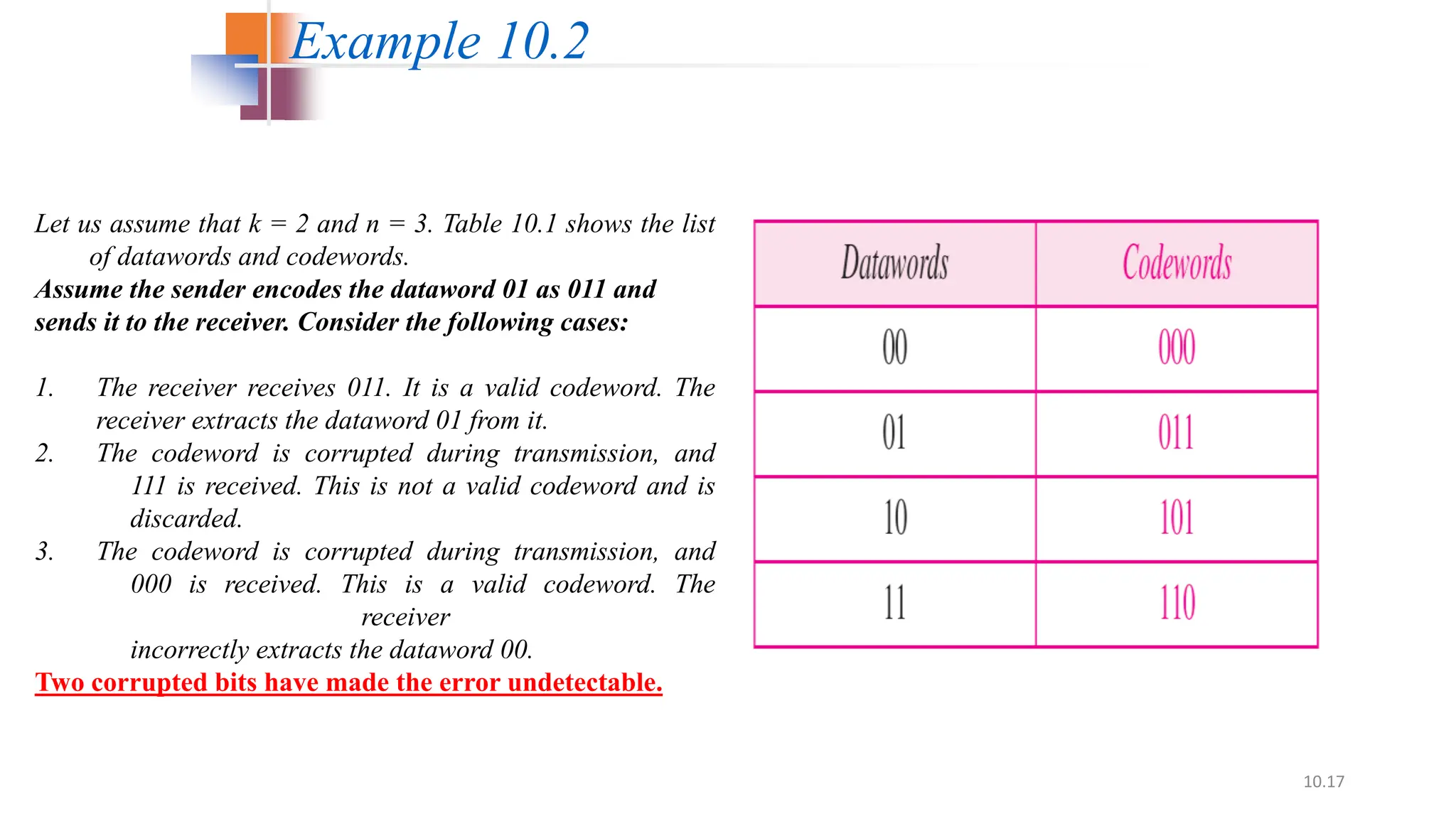
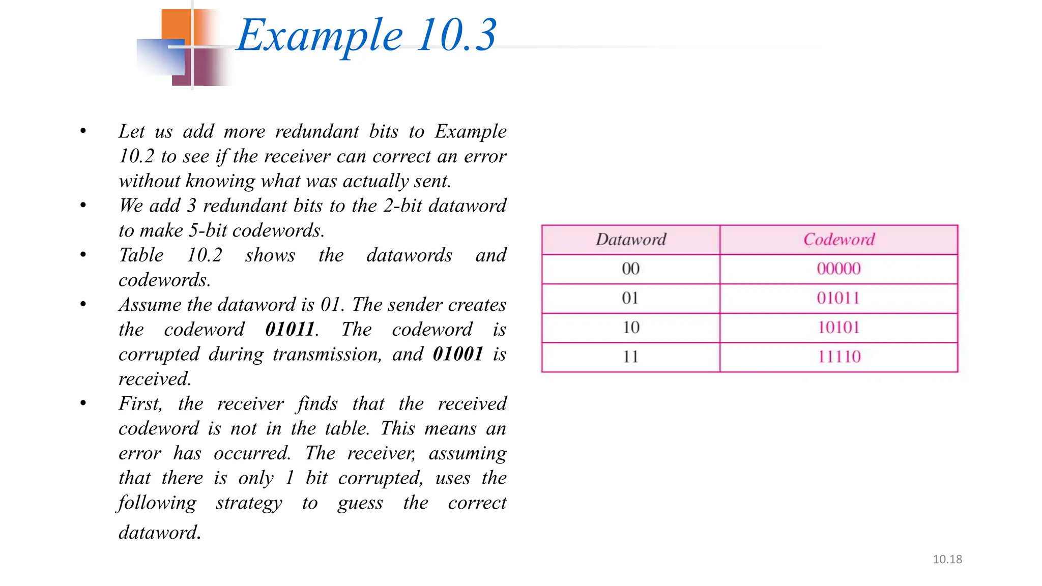
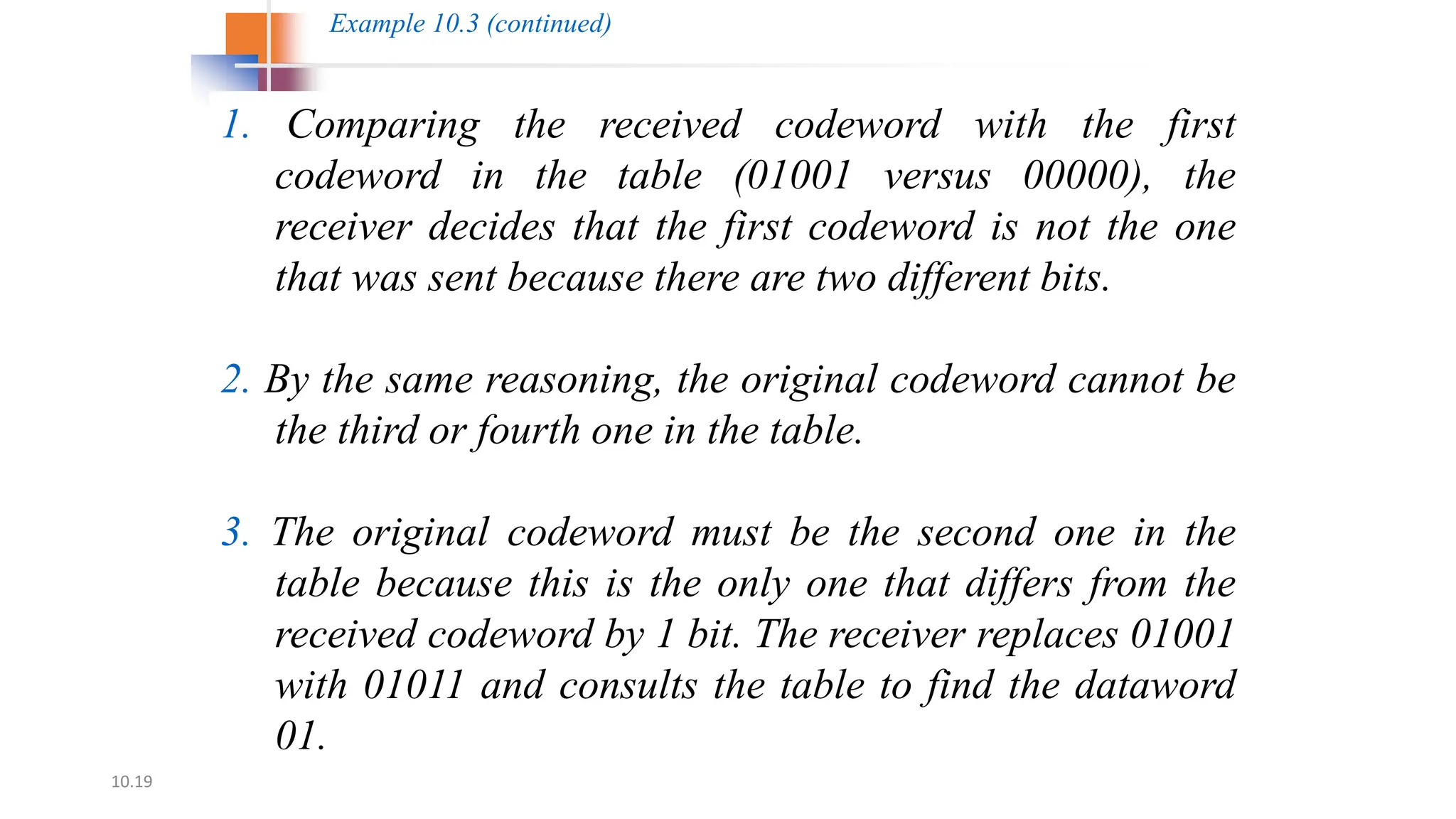
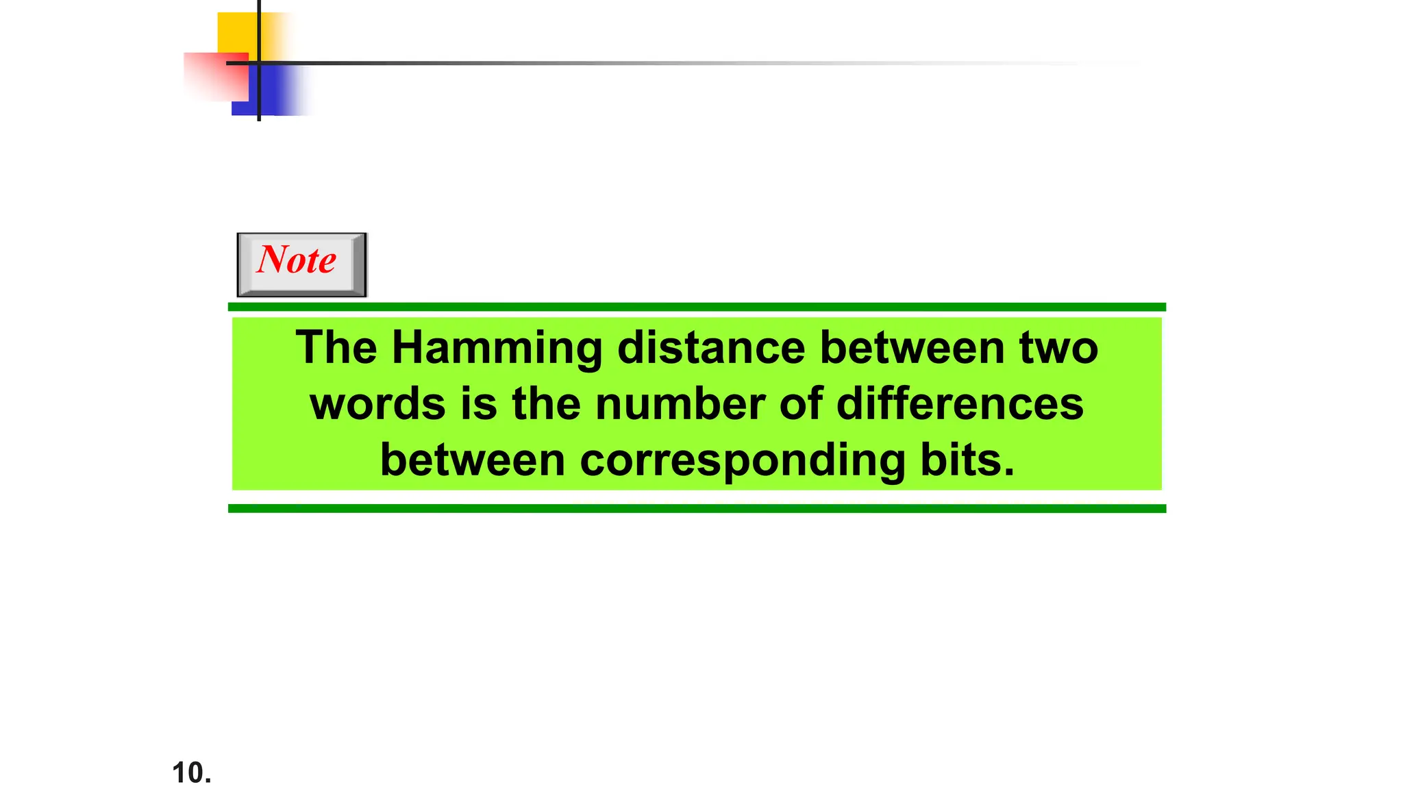
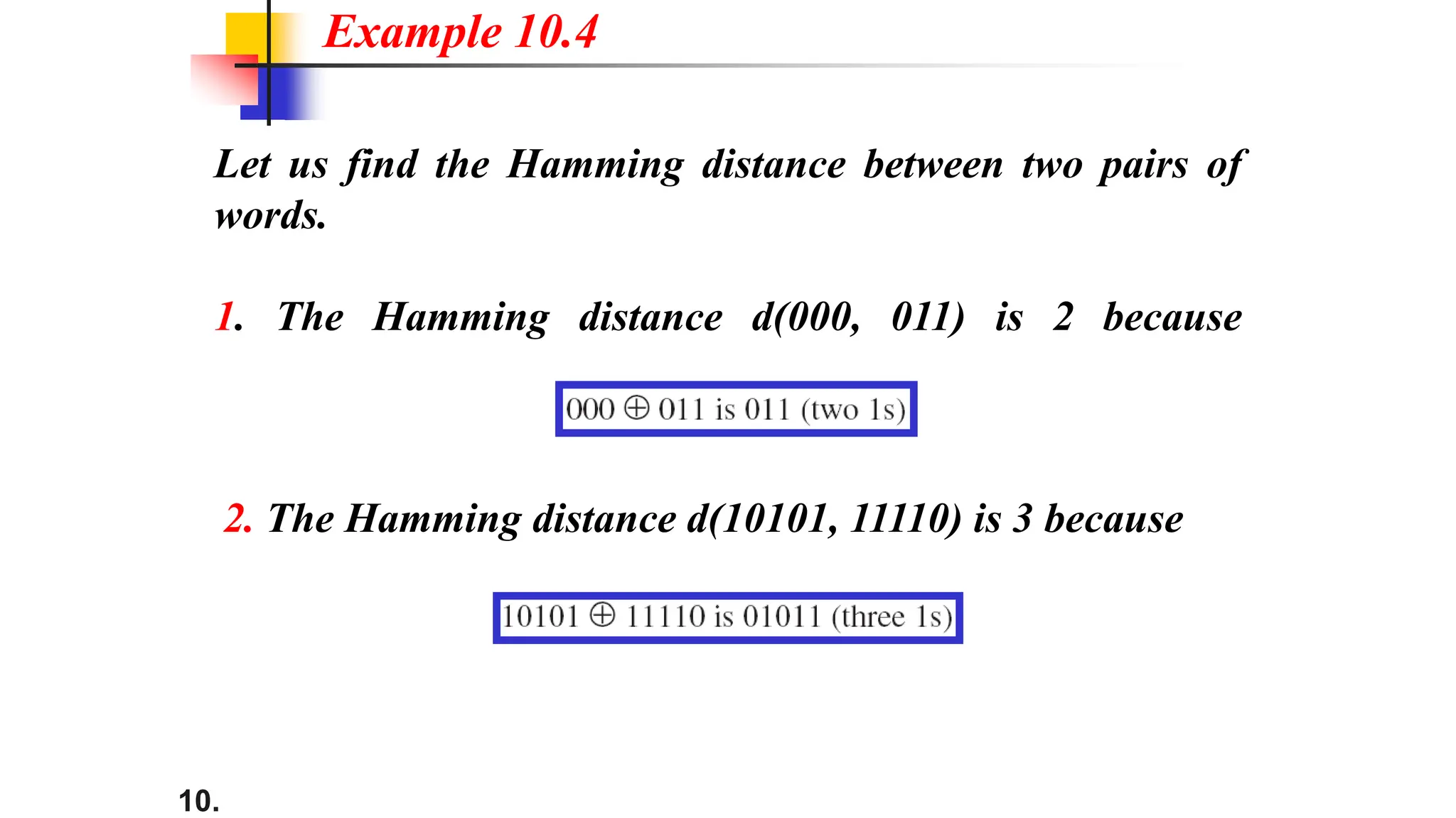
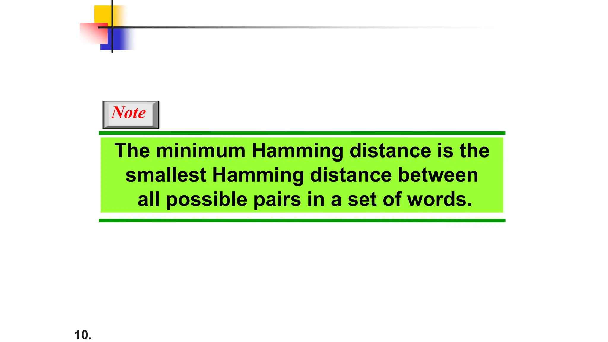
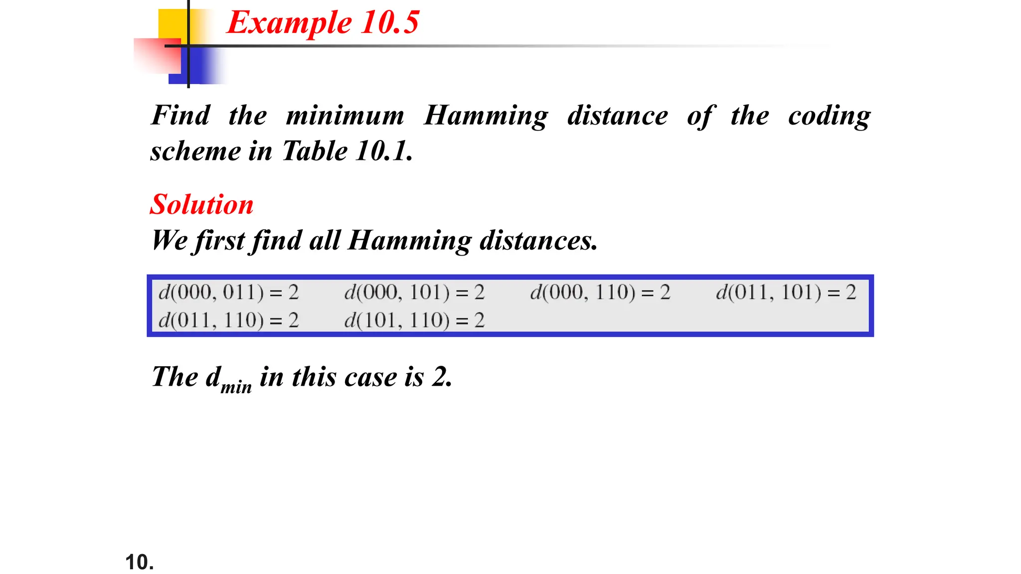
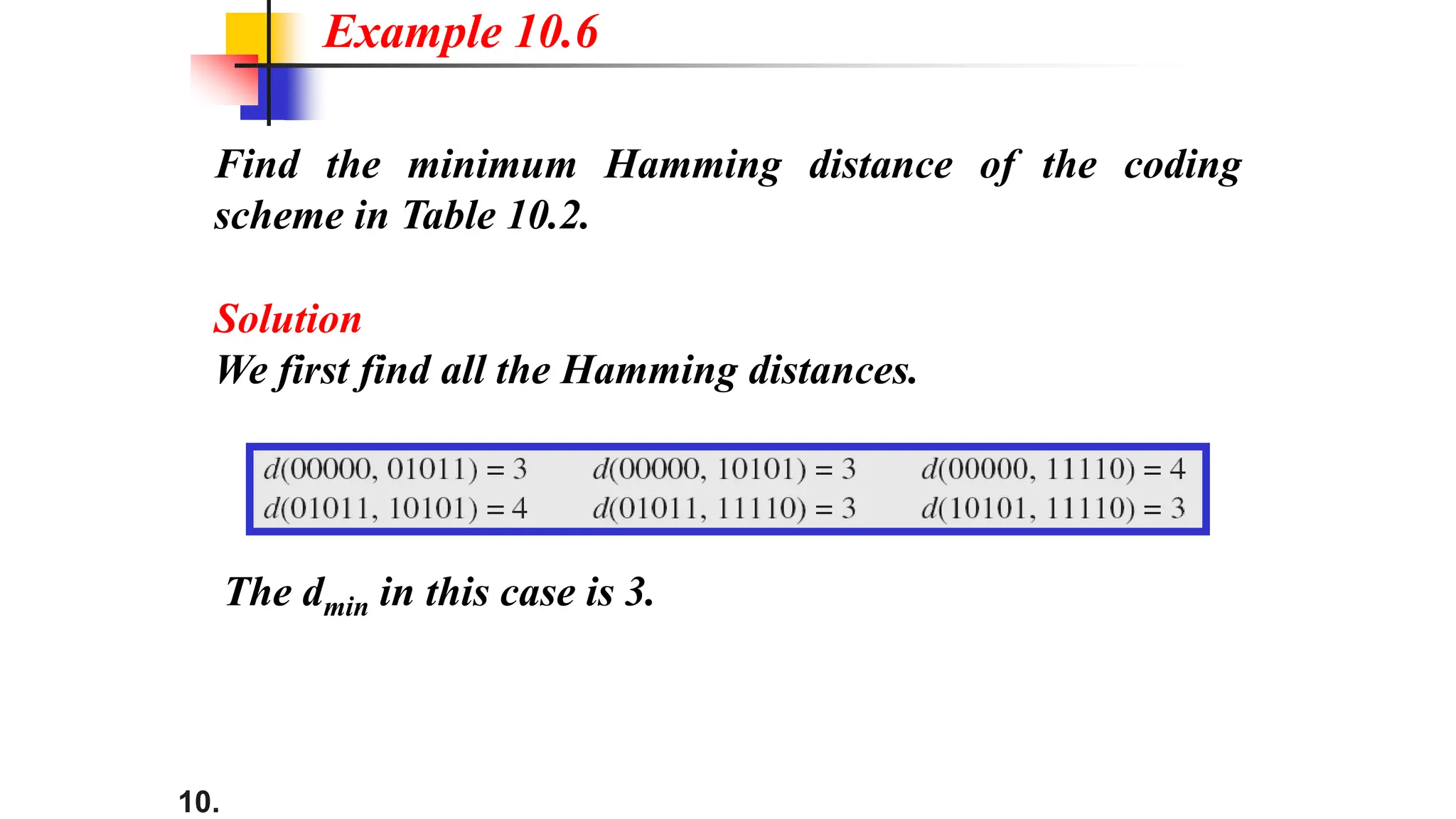
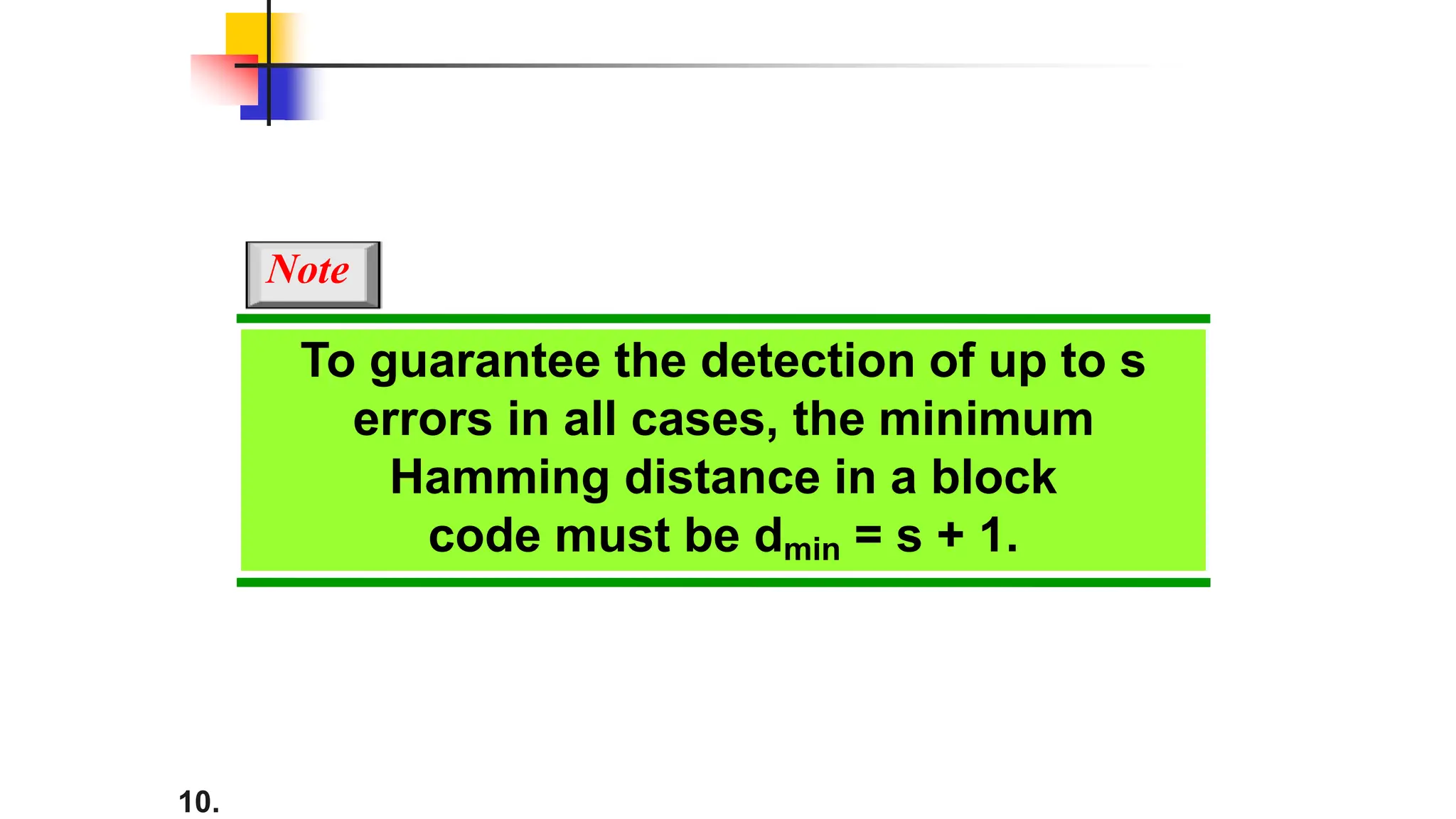
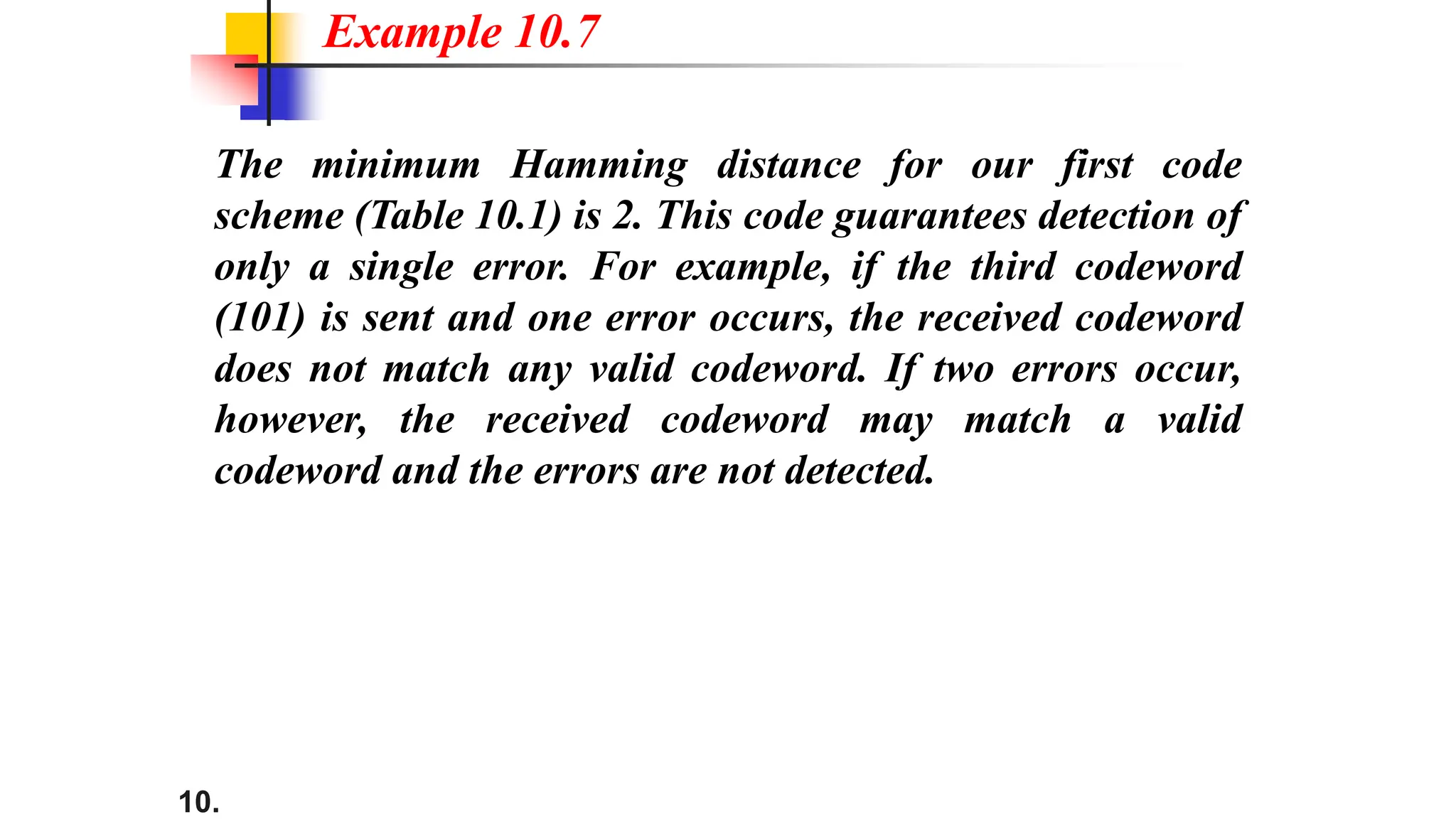
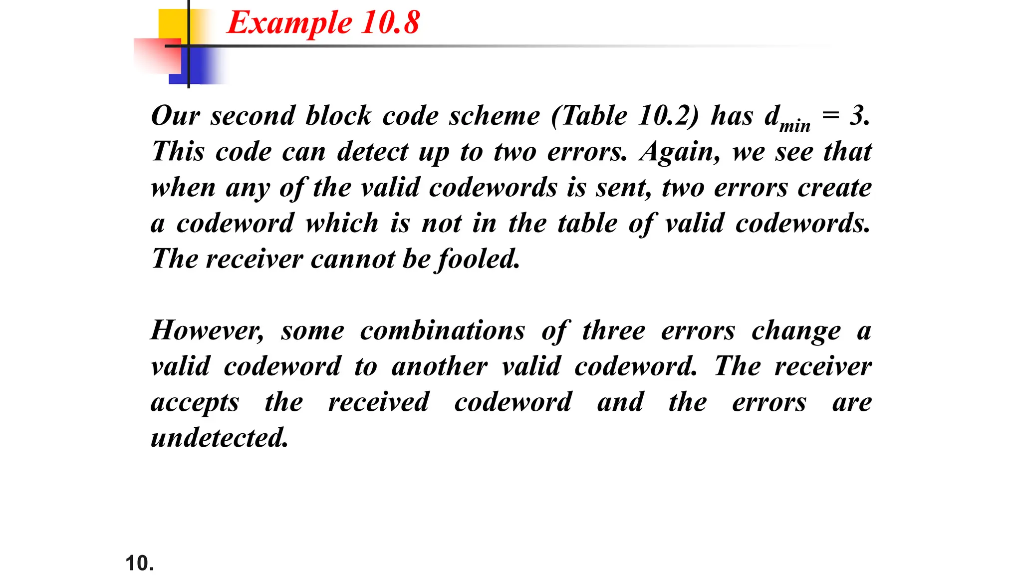
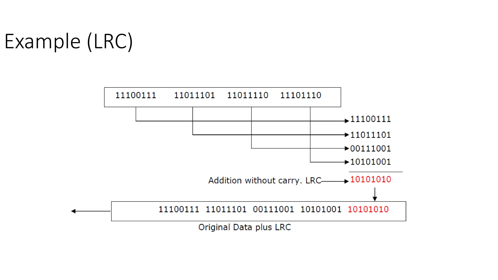
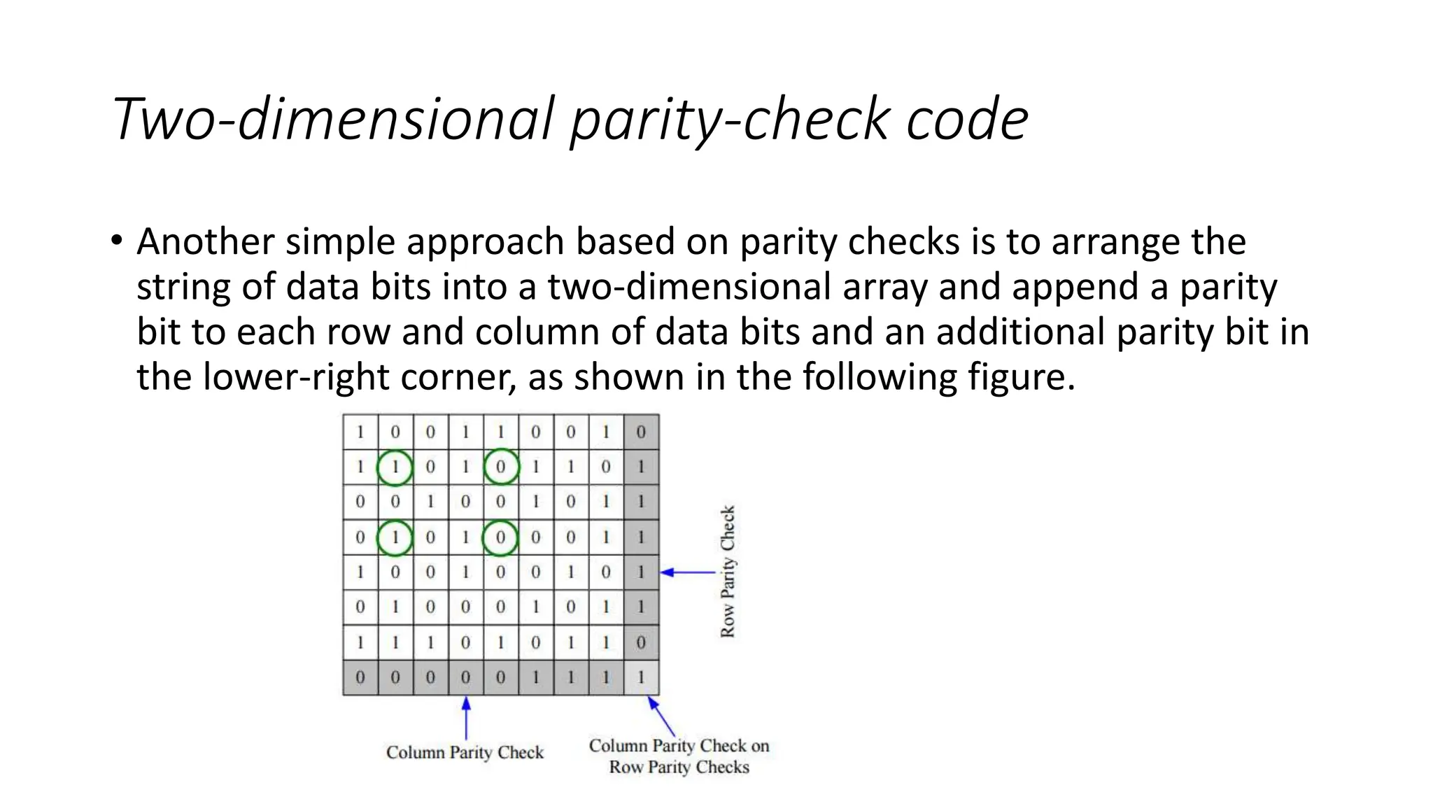
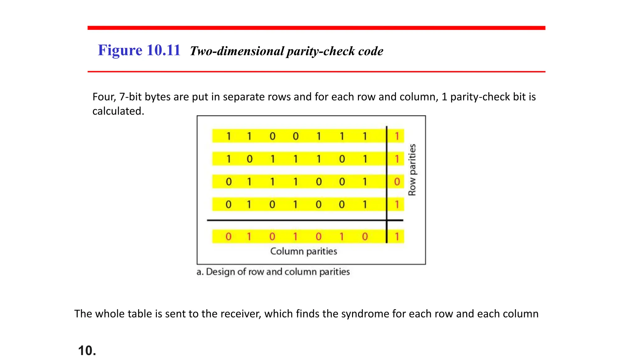
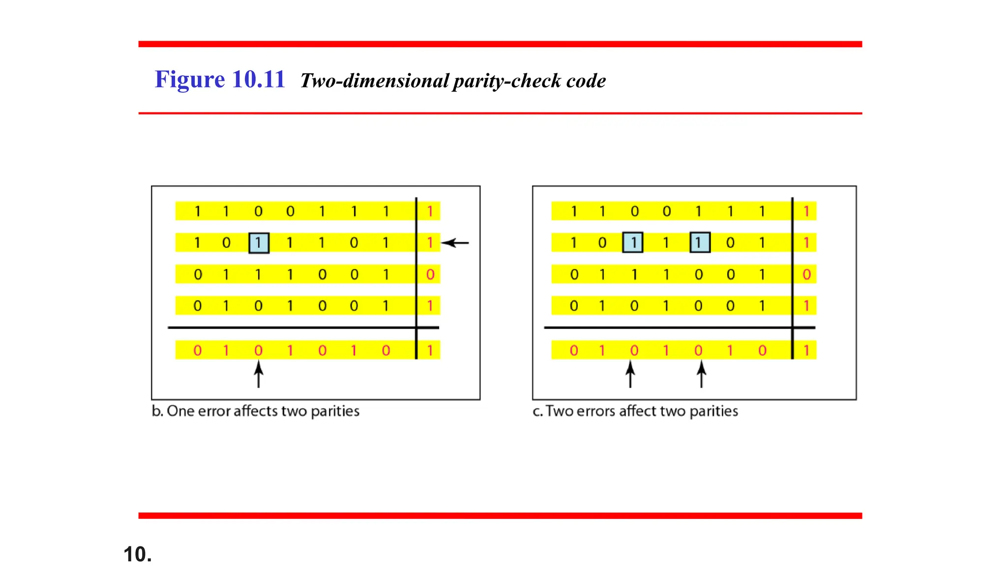
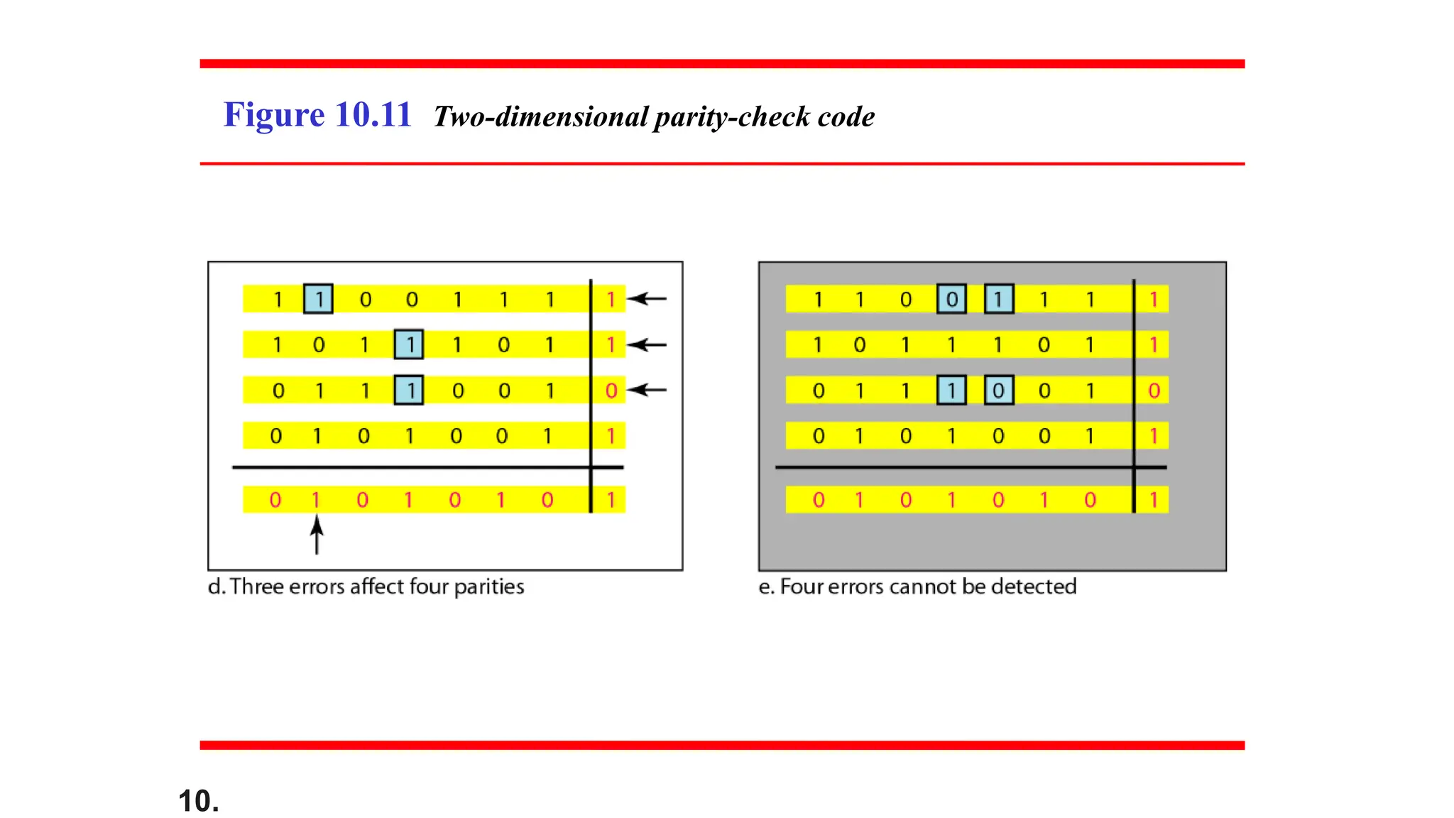
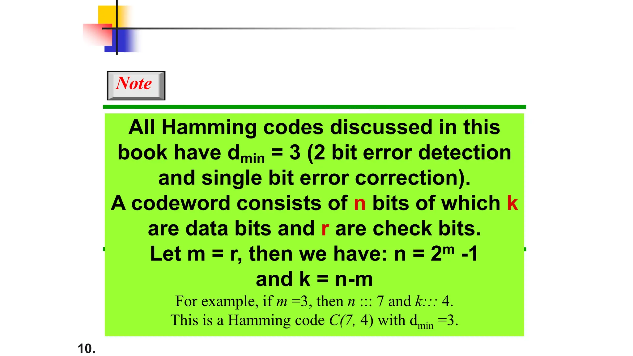
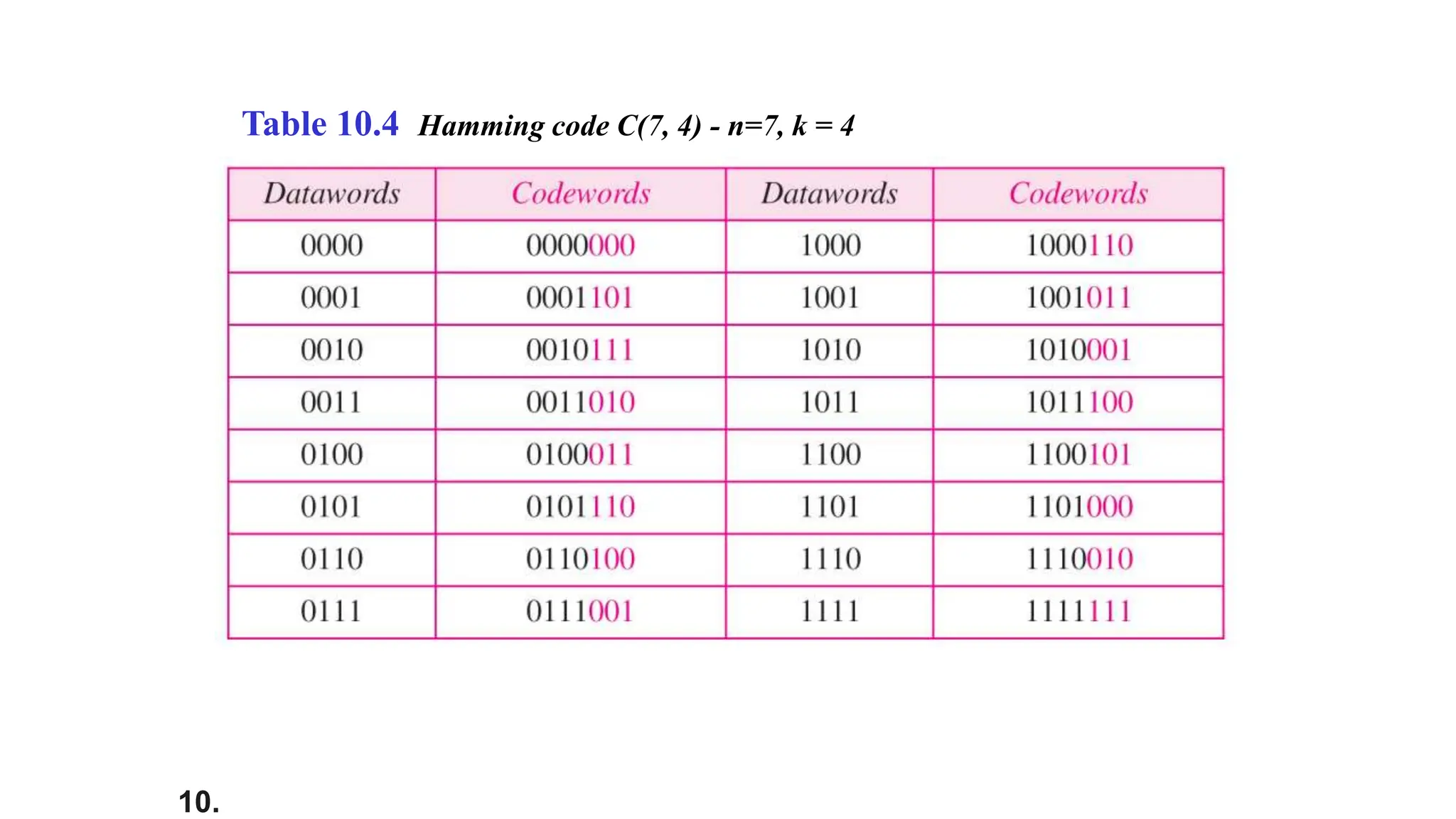
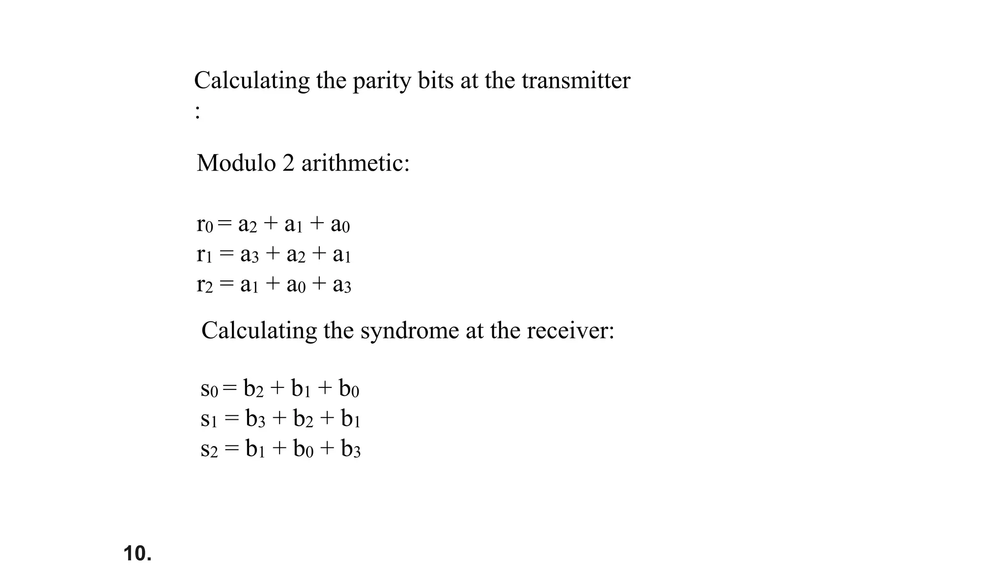
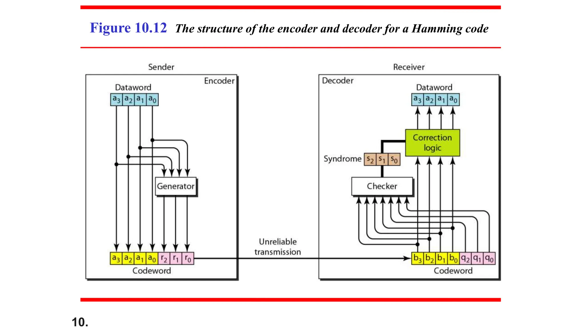
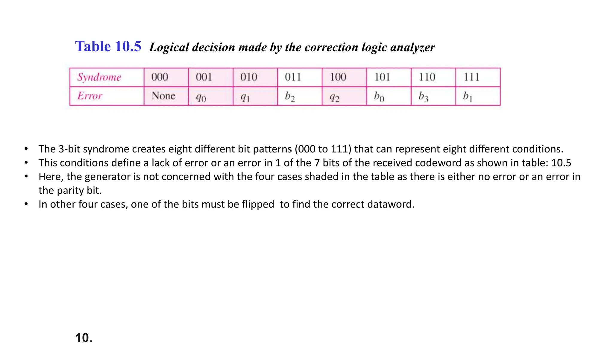
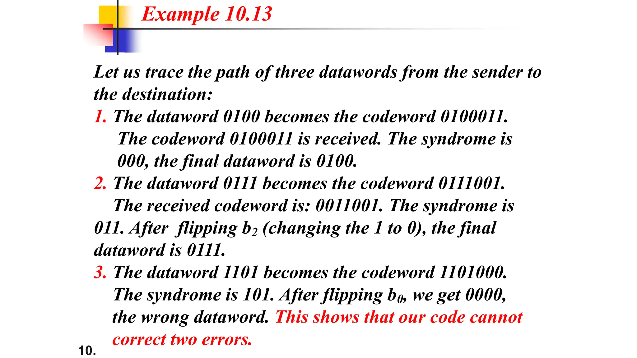
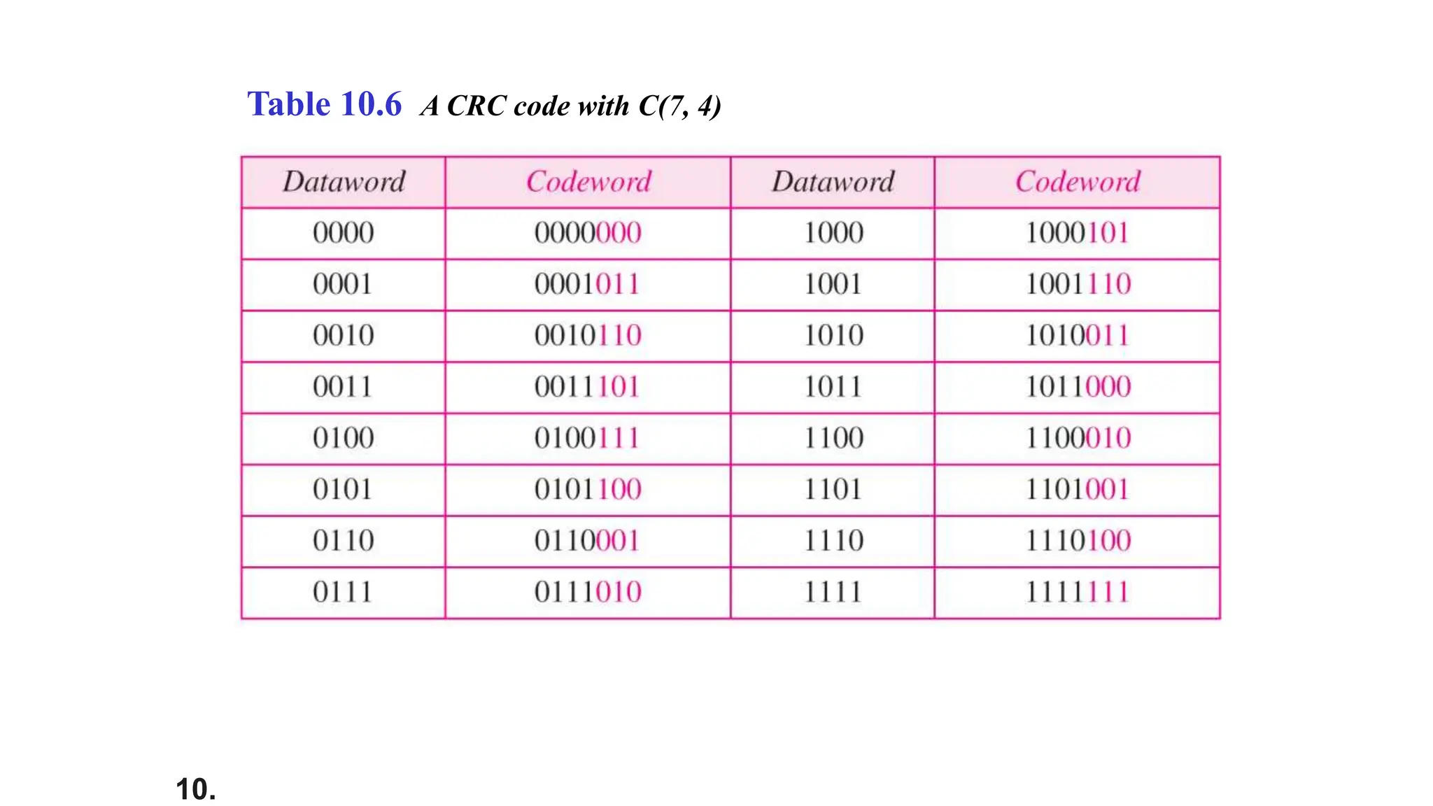
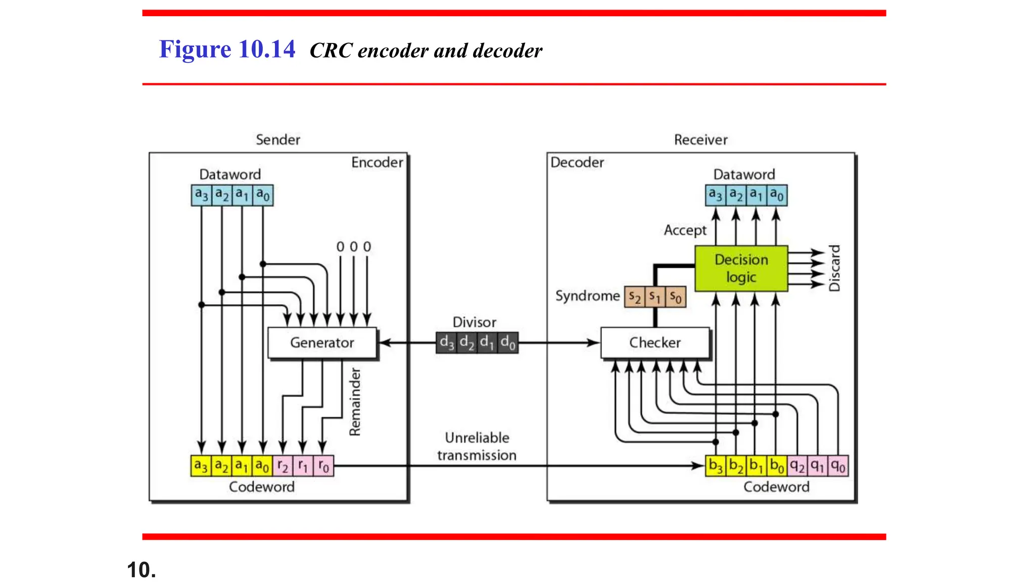
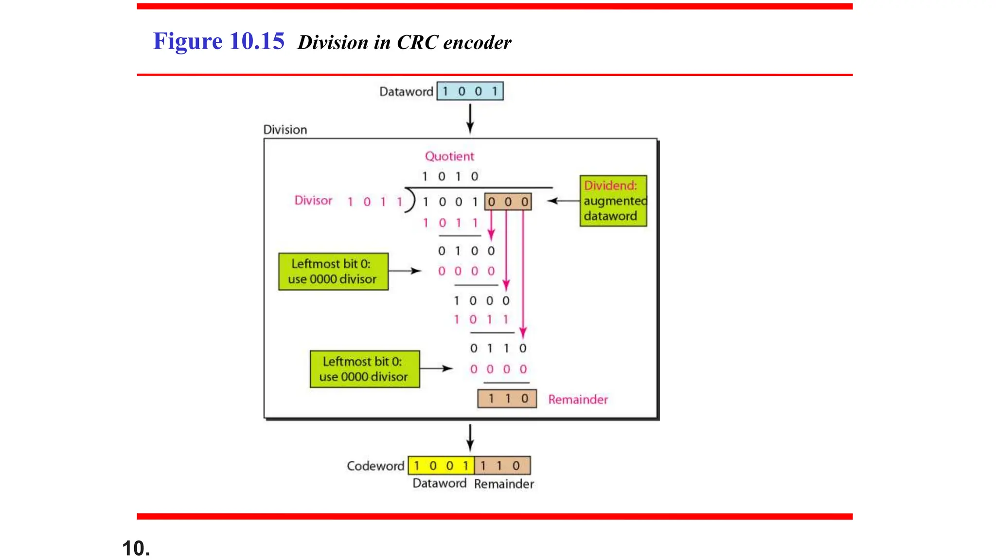
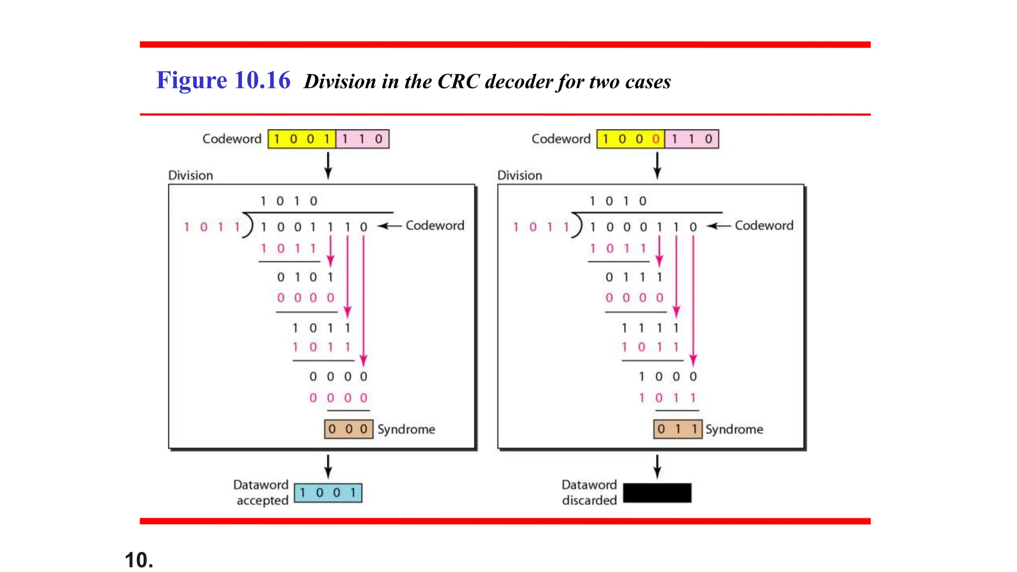
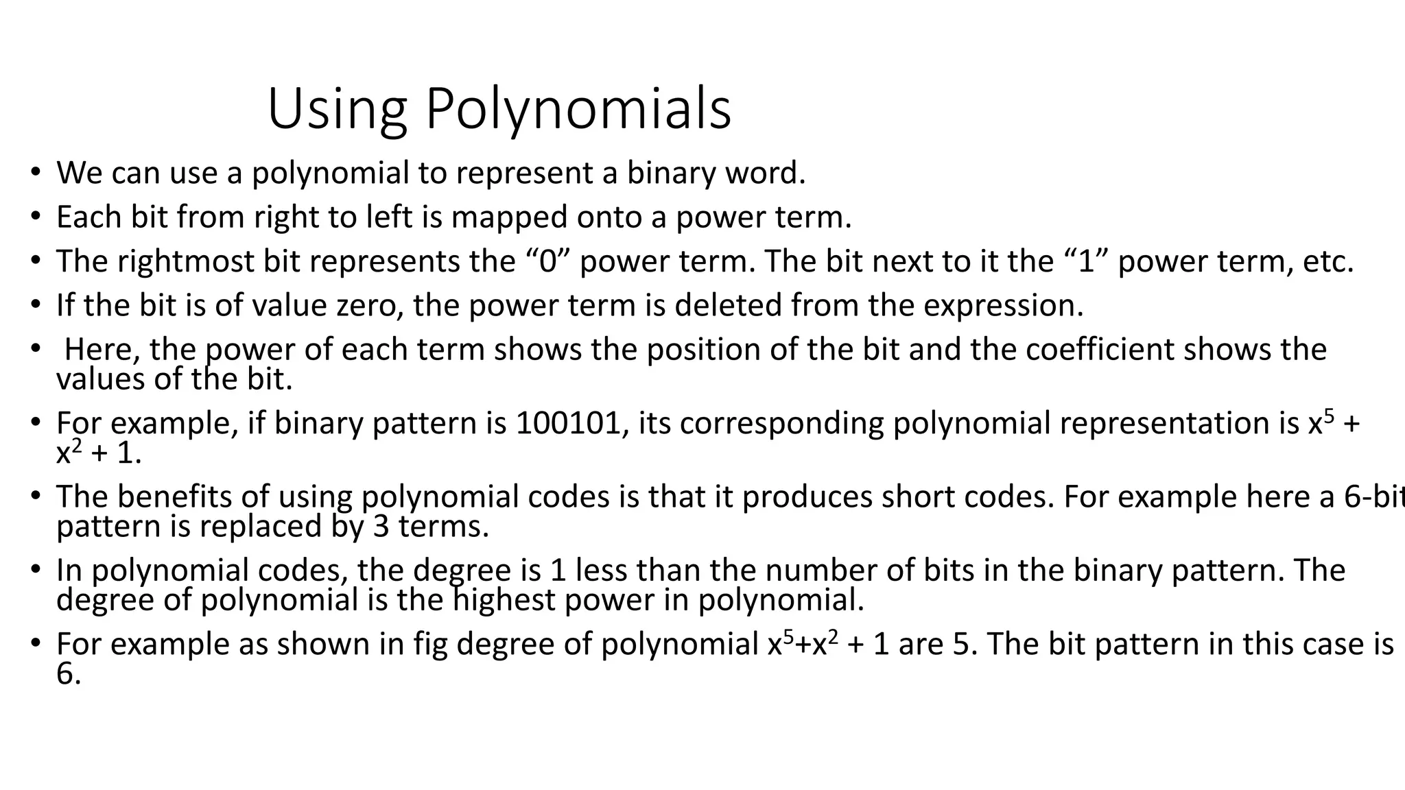
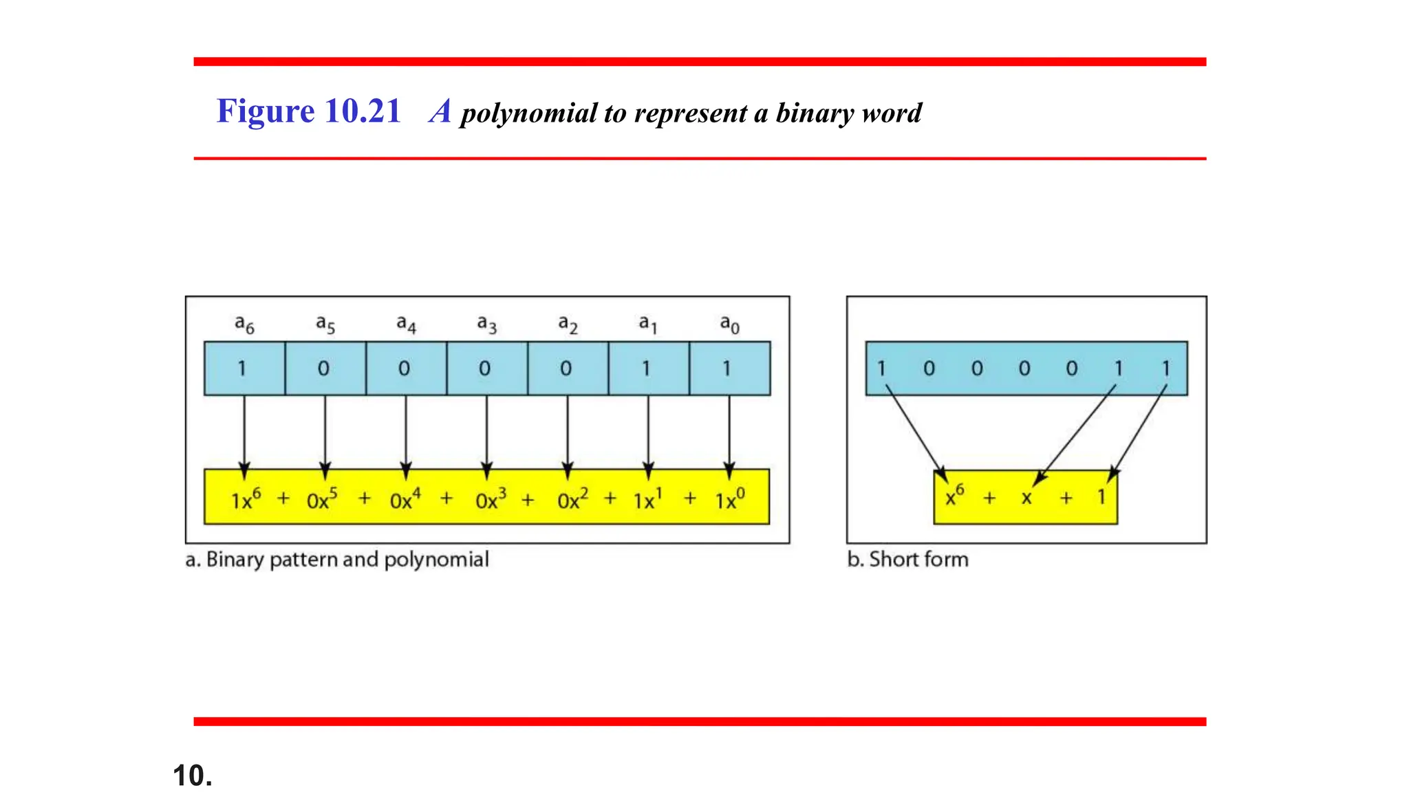
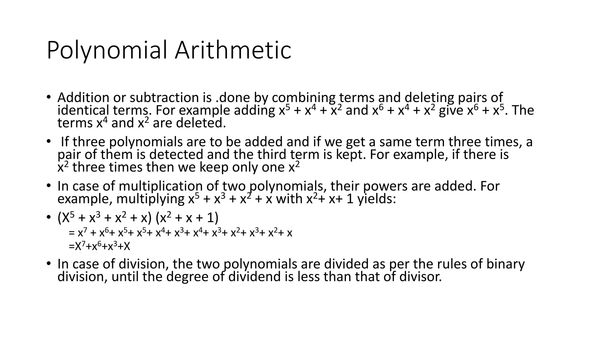
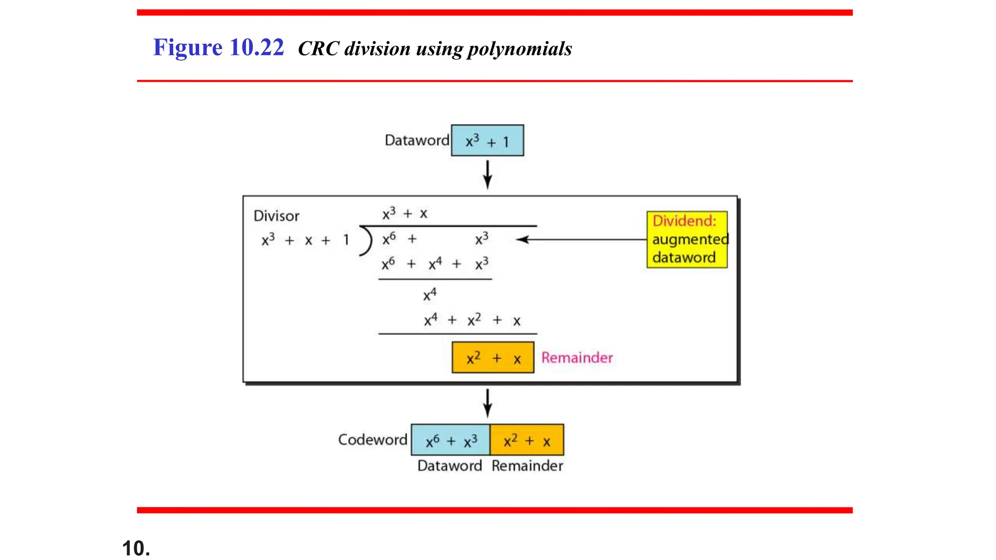
This document discusses error detection and correction. It begins by defining different types of errors that can occur like single-bit and multiple-bit errors. It then discusses concepts like redundancy and error detection vs correction. Specific error detection and correction techniques are covered such as block coding, forward error correction vs retransmission, linear block codes including Hamming codes and cyclic redundancy checks (CRC). Worked examples are provided to illustrate key concepts.
This document provides an overview of error detection and correction techniques used in digital communications. It discusses different types of errors that can occur like single-bit and burst errors. It explains that extra redundant bits must be sent along with data to detect or correct errors. Various block coding techniques are described like adding parity bits in simple parity codes or generating codewords from datawords in Hamming codes to guarantee detection of certain number of errors. The concepts of Hamming distance, minimum Hamming distance, and linear block codes are covered. Cyclic codes that have the property of rotation are also discussed along with the cyclic redundancy check technique.
This document discusses error detection and correction in digital communications. It begins with an introduction to different types of errors that can occur like single-bit errors and burst errors. It explains that redundancy is needed to detect or correct errors. It then discusses various block coding techniques used for error detection and correction including linear block codes, cyclic codes, and cyclic redundancy checks. Specific error correcting codes like Hamming codes and parity checks are explained through examples. The key aspects of error detection capability, minimum Hamming distance, and generator polynomials in cyclic codes are covered.
This document discusses error detection and correction in digital communications. It begins by introducing different types of errors that can occur during data transmission and explains the need for redundancy to detect and correct errors. It then covers various block coding techniques used for error detection and correction, including linear block codes, Hamming codes, and cyclic codes such as cyclic redundancy checks (CRCs). Key concepts discussed include single-bit and burst errors, minimum Hamming distance, encoding and decoding processes, and the properties and advantages of different coding schemes.
This document discusses error detection and correction techniques for digital data transmission. It introduces different types of errors that can occur, such as single-bit and burst errors. It describes how redundancy is used to detect and correct errors using block coding techniques. Specific examples are provided to illustrate how block codes are constructed and used to detect and correct errors. Key concepts discussed include linear block codes, Hamming distance, minimum Hamming distance, and how these relate to the error detection and correction capabilities of different coding schemes.
This document provides an overview of error detection and correction techniques in digital communications. It discusses different types of errors that can occur like single-bit and burst errors. It explains how redundancy is used to detect and correct errors. Block coding techniques are described that divide messages into blocks and add redundant bits to create codewords. Linear block codes are introduced where the XOR of two codewords results in another valid codeword. Simple parity-check codes are discussed as a basic error detecting code using a single redundant bit. Examples are provided to illustrate concepts like minimum Hamming distance, error detection and correction capabilities of different codes.
Data Link Layer- Error Detection and Control_2.pptxArunVerma37053
The document discusses the data link layer and its objectives. The data link layer transforms the physical layer into a link responsible for node-to-node communication. Specific responsibilities of the data link layer include framing, addressing, flow control, error control, and media access control. It divides data into frames, adds header information, implements flow control mechanisms, and adds reliability through error detection and retransmission of damaged frames. When multiple devices share the same link, data link protocols determine which device has control over the link.
This document discusses error detection and correction techniques used in data transmission. It covers various types of errors that can occur during transmission and different coding schemes used for error detection and correction, including block coding, linear block coding, cyclic codes, and cyclic redundancy checks (CRCs). Specific examples are provided to illustrate how Hamming codes, parity checks, and CRCs can detect and correct single-bit and burst errors. Key concepts covered include redundancy, minimum Hamming distance, encoding/decoding processes, and the use of polynomials to represent binary words in CRC calculations.
This document provides an overview of error detection and correction techniques in data transmission. It discusses different types of errors that can occur like single-bit and burst errors. It introduces concepts like redundancy, block coding, linear block codes, cyclic codes, and checksums using cyclic redundancy checks (CRCs). Specific error detection and correction codes are presented like parity checks, Hamming codes, and CRC codes. Worked examples are provided to illustrate how these codes detect and sometimes correct errors. Key metrics like minimum Hamming distance that determine error detection and correction capabilities are explained.
This presentation covers the type of errors during data transmission on a network. It also explains the strategies needed to detect and correct errors during data transmission. Error occurs when user receives unexpected data that was changed during transmission. There are two types of errors: Single bit error and Burst Error.
This document discusses error detection and correction techniques for digital data transmission. It introduces different types of errors that can occur during transmission, including single-bit and burst errors. Error detection and correction require adding redundant bits to the data. Block coding divides data into blocks and adds redundant bits to each block to create codewords. Simple parity-check codes can detect single-bit errors by adding one redundant bit. Hamming codes have higher error detection and correction capabilities and can detect up to two errors and correct single errors. The document provides examples to illustrate linear block codes, minimum Hamming distance, and how Hamming codes work.
This document summarizes error detection and correction techniques. It discusses types of errors like single-bit errors and burst errors. It covers basic concepts of error detection, including adding redundant bits and using techniques like parity checks. Error correction requires knowing the number and positions of errors. Linear block codes and cyclic codes are introduced. Hamming distance and minimum distance are important metrics for error detection and correction capability. Specific codes like parity codes, Hamming codes, and cyclic redundancy checks (CRCs) are described through examples.
This document discusses error detection and correction in data transmission. It begins with an introduction to types of errors like single-bit and burst errors. It then discusses key concepts like error detection, correction, and forward error correction versus retransmission. The document focuses on block coding techniques for error detection and correction. It explains linear block codes and provides examples of parity-check codes and Hamming codes. Parity-check codes can detect single and odd number of errors while Hamming codes can detect and correct errors.
This document discusses error detection and correction techniques for digital data transmission. It introduces different types of errors that can occur like single-bit and burst errors. It explains that redundancy is needed to detect or correct errors. Various coding techniques are described, including block coding, linear block codes, cyclic codes, and checksums. Specific codes like parity-check codes, Hamming codes, and cyclic redundancy checks are explained in detail with examples. The document emphasizes that error detection codes can only detect certain error types, while error correction codes can correct errors.
SYBSC IT COMPUTER NETWORKS UNIT II Error Detection and CorrectionArti Parab Academics
Introduction to the Data Link Layer: Link layer addressing, Data Link Layer Design Issues, Error detection and correction, block coding, cyclic codes, checksum, forward error correction, error correcting codes, error detecting codes.
The document discusses error detection and correction techniques at the data link layer. It describes how errors can occur during data transmission and the need for reliable communication. Error detection allows a receiver to detect errors while error correction enables identifying and correcting bit errors without retransmission. Common techniques discussed include parity checks, checksums, and cyclic redundancy checks which add redundant bits to detect errors. CRC is based on binary division of data and checksum on addition. Forward error correction and retransmission are compared. Coding schemes use redundancy to detect or correct errors.
Human: Thank you for the summary. Can you provide a 2 sentence summary that captures the key aspects?
This document discusses error detection and correction techniques for digital data transmission. It covers various types of errors that can occur like single-bit and burst errors. It also describes different coding schemes used for error detection and correction including block coding, linear block codes, cyclic codes, and checksums. Specific codes discussed include parity-bit codes, Hamming codes, and cyclic redundancy checks (CRCs). The techniques are evaluated based on their error detection and correction capabilities as defined by concepts like minimum Hamming distance.
This document discusses error detection and correction in digital communications. It introduces block coding where messages are divided into blocks of k bits with r redundant bits added to each block, making the block length n=k+r. Linear block codes are discussed where the XOR of two codewords results in a third valid codeword. The minimum Hamming distance dmin relates to the error detection and correction capabilities of a code, with dmin=s+1 needed to detect s errors and dmin=2t+1 to correct t errors. Examples are given of simple parity-check codes and generating codewords from datawords.
This document discusses error detection and correction in digital communications. It begins by explaining the different types of errors that can occur like single-bit and burst errors. It then introduces the concept of adding redundant bits to detect or correct errors. The document focuses on block coding, where the message is divided into blocks and redundant bits are added to each block to form a codeword. Error detection codes are able to detect errors but not correct them, while error correction codes can correct errors by encoding extra redundant bits. Examples of block codes for error detection and correction are provided to illustrate these concepts.
Data Communication And Networking - ERROR DETECTION AND CORRECTIONAvijeet Negel
This document discusses error detection and correction in digital communications. It begins by explaining the different types of errors that can occur like single-bit and burst errors. It then introduces the concept of adding redundant bits to detect or correct errors. The document focuses on block coding, where the message is divided into blocks and redundant bits are added to each block to form a codeword. Error detection codes are able to detect errors but not correct them, while error correction codes can correct errors by encoding extra redundant bits. Examples of block codes for error detection and correction are provided to illustrate these concepts.
This document discusses error detection and correction in digital communications. It begins by explaining the different types of errors that can occur like single-bit and burst errors. It then introduces the concept of adding redundancy through extra bits to detect or correct errors. Block coding is described as a method of dividing messages into fixed-length blocks and adding redundant bits to each block. Error detection codes are able to detect errors but not correct them, while error correction codes can correct a certain number of errors without knowing their location. Examples are provided to illustrate how error detection and correction work using simple block codes.
This document discusses error detection and correction techniques using Hamming codes and cyclic redundancy checks (CRCs). It explains key concepts like Hamming distance, minimum distance, linear block codes, and cyclic codes. Examples are provided to illustrate how Hamming codes can detect up to two errors and correct one error using a minimum distance of 3. CRC codes are also examined, showing how they use polynomial division to detect errors. The advantages of cyclic codes for hardware implementation are noted.
This document discusses error detection and correction techniques for digital communications. It covers Hamming codes, cyclic redundancy checks (CRCs), checksums, and other coding schemes. Key points include:
- Hamming codes can detect up to two errors and correct single errors by ensuring a minimum Hamming distance of 3 between codewords.
- CRCs use cyclic codes to detect errors, with the CRC value serving as a checksum. CRC division and hardware implementations are examined.
- Cyclic codes have the property that cyclically shifting a codeword results in another valid codeword. This allows for efficient encoding and decoding.
- Checksums involve sending the sum of message bits along with the message for the receiver to
This document discusses error detection and correction techniques used in digital communications. It covers Hamming codes, cyclic redundancy checks (CRCs), checksums, and linear block codes. Key points include:
- Hamming codes can detect up to two errors and correct single errors by ensuring a minimum Hamming distance of 3 between codewords.
- CRCs use cyclic codes to detect errors by calculating syndromes based on polynomial division of the received codeword by a generator polynomial.
- Checksums involve sending the sum of data words along with the words to detect errors by verifying the received sum is correct.
- Linear block codes allow the XOR of any two valid codewords to produce another valid codeword.
Similar to Lecture8_Error Detection and Correction 232.pptx (20)
Software Engineering and Project Management - Introduction, Modeling Concepts...Prakhyath Rai
Introduction, Modeling Concepts and Class Modeling: What is Object orientation? What is OO development? OO Themes; Evidence for usefulness of OO development; OO modeling history. Modeling
as Design technique: Modeling, abstraction, The Three models. Class Modeling: Object and Class Concept, Link and associations concepts, Generalization and Inheritance, A sample class model, Navigation of class models, and UML diagrams
Building the Analysis Models: Requirement Analysis, Analysis Model Approaches, Data modeling Concepts, Object Oriented Analysis, Scenario-Based Modeling, Flow-Oriented Modeling, class Based Modeling, Creating a Behavioral Model.
Introduction- e - waste – definition - sources of e-waste– hazardous substances in e-waste - effects of e-waste on environment and human health- need for e-waste management– e-waste handling rules - waste minimization techniques for managing e-waste – recycling of e-waste - disposal treatment methods of e- waste – mechanism of extraction of precious metal from leaching solution-global Scenario of E-waste – E-waste in India- case studies.
Use PyCharm for remote debugging of WSL on a Windo cf5c162d672e4e58b4dde5d797...shadow0702a
This document serves as a comprehensive step-by-step guide on how to effectively use PyCharm for remote debugging of the Windows Subsystem for Linux (WSL) on a local Windows machine. It meticulously outlines several critical steps in the process, starting with the crucial task of enabling permissions, followed by the installation and configuration of WSL.
The guide then proceeds to explain how to set up the SSH service within the WSL environment, an integral part of the process. Alongside this, it also provides detailed instructions on how to modify the inbound rules of the Windows firewall to facilitate the process, ensuring that there are no connectivity issues that could potentially hinder the debugging process.
The document further emphasizes on the importance of checking the connection between the Windows and WSL environments, providing instructions on how to ensure that the connection is optimal and ready for remote debugging.
It also offers an in-depth guide on how to configure the WSL interpreter and files within the PyCharm environment. This is essential for ensuring that the debugging process is set up correctly and that the program can be run effectively within the WSL terminal.
Additionally, the document provides guidance on how to set up breakpoints for debugging, a fundamental aspect of the debugging process which allows the developer to stop the execution of their code at certain points and inspect their program at those stages.
Finally, the document concludes by providing a link to a reference blog. This blog offers additional information and guidance on configuring the remote Python interpreter in PyCharm, providing the reader with a well-rounded understanding of the process.
Null Bangalore | Pentesters Approach to AWS IAMDivyanshu
#Abstract:
- Learn more about the real-world methods for auditing AWS IAM (Identity and Access Management) as a pentester. So let us proceed with a brief discussion of IAM as well as some typical misconfigurations and their potential exploits in order to reinforce the understanding of IAM security best practices.
- Gain actionable insights into AWS IAM policies and roles, using hands on approach.
#Prerequisites:
- Basic understanding of AWS services and architecture
- Familiarity with cloud security concepts
- Experience using the AWS Management Console or AWS CLI.
- For hands on lab create account on [killercoda.com](https://killercoda.com/cloudsecurity-scenario/)
# Scenario Covered:
- Basics of IAM in AWS
- Implementing IAM Policies with Least Privilege to Manage S3 Bucket
- Objective: Create an S3 bucket with least privilege IAM policy and validate access.
- Steps:
- Create S3 bucket.
- Attach least privilege policy to IAM user.
- Validate access.
- Exploiting IAM PassRole Misconfiguration
-Allows a user to pass a specific IAM role to an AWS service (ec2), typically used for service access delegation. Then exploit PassRole Misconfiguration granting unauthorized access to sensitive resources.
- Objective: Demonstrate how a PassRole misconfiguration can grant unauthorized access.
- Steps:
- Allow user to pass IAM role to EC2.
- Exploit misconfiguration for unauthorized access.
- Access sensitive resources.
- Exploiting IAM AssumeRole Misconfiguration with Overly Permissive Role
- An overly permissive IAM role configuration can lead to privilege escalation by creating a role with administrative privileges and allow a user to assume this role.
- Objective: Show how overly permissive IAM roles can lead to privilege escalation.
- Steps:
- Create role with administrative privileges.
- Allow user to assume the role.
- Perform administrative actions.
- Differentiation between PassRole vs AssumeRole
Try at [killercoda.com](https://killercoda.com/cloudsecurity-scenario/)
Redefining brain tumor segmentation: a cutting-edge convolutional neural netw...IJECEIAES
Medical image analysis has witnessed significant advancements with deep learning techniques. In the domain of brain tumor segmentation, the ability to
precisely delineate tumor boundaries from magnetic resonance imaging (MRI)
scans holds profound implications for diagnosis. This study presents an ensemble convolutional neural network (CNN) with transfer learning, integrating
the state-of-the-art Deeplabv3+ architecture with the ResNet18 backbone. The
model is rigorously trained and evaluated, exhibiting remarkable performance
metrics, including an impressive global accuracy of 99.286%, a high-class accuracy of 82.191%, a mean intersection over union (IoU) of 79.900%, a weighted
IoU of 98.620%, and a Boundary F1 (BF) score of 83.303%. Notably, a detailed comparative analysis with existing methods showcases the superiority of
our proposed model. These findings underscore the model’s competence in precise brain tumor localization, underscoring its potential to revolutionize medical
image analysis and enhance healthcare outcomes. This research paves the way
for future exploration and optimization of advanced CNN models in medical
imaging, emphasizing addressing false positives and resource efficiency.
Optimizing Gradle Builds - Gradle DPE Tour Berlin 2024Sinan KOZAK
Sinan from the Delivery Hero mobile infrastructure engineering team shares a deep dive into performance acceleration with Gradle build cache optimizations. Sinan shares their journey into solving complex build-cache problems that affect Gradle builds. By understanding the challenges and solutions found in our journey, we aim to demonstrate the possibilities for faster builds. The case study reveals how overlapping outputs and cache misconfigurations led to significant increases in build times, especially as the project scaled up with numerous modules using Paparazzi tests. The journey from diagnosing to defeating cache issues offers invaluable lessons on maintaining cache integrity without sacrificing functionality.
Embedded machine learning-based road conditions and driving behavior monitoringIJECEIAES
Car accident rates have increased in recent years, resulting in losses in human lives, properties, and other financial costs. An embedded machine learning-based system is developed to address this critical issue. The system can monitor road conditions, detect driving patterns, and identify aggressive driving behaviors. The system is based on neural networks trained on a comprehensive dataset of driving events, driving styles, and road conditions. The system effectively detects potential risks and helps mitigate the frequency and impact of accidents. The primary goal is to ensure the safety of drivers and vehicles. Collecting data involved gathering information on three key road events: normal street and normal drive, speed bumps, circular yellow speed bumps, and three aggressive driving actions: sudden start, sudden stop, and sudden entry. The gathered data is processed and analyzed using a machine learning system designed for limited power and memory devices. The developed system resulted in 91.9% accuracy, 93.6% precision, and 92% recall. The achieved inference time on an Arduino Nano 33 BLE Sense with a 32-bit CPU running at 64 MHz is 34 ms and requires 2.6 kB peak RAM and 139.9 kB program flash memory, making it suitable for resource-constrained embedded systems.
Electric vehicle and photovoltaic advanced roles in enhancing the financial p...IJECEIAES
Climate change's impact on the planet forced the United Nations and governments to promote green energies and electric transportation. The deployments of photovoltaic (PV) and electric vehicle (EV) systems gained stronger momentum due to their numerous advantages over fossil fuel types. The advantages go beyond sustainability to reach financial support and stability. The work in this paper introduces the hybrid system between PV and EV to support industrial and commercial plants. This paper covers the theoretical framework of the proposed hybrid system including the required equation to complete the cost analysis when PV and EV are present. In addition, the proposed design diagram which sets the priorities and requirements of the system is presented. The proposed approach allows setup to advance their power stability, especially during power outages. The presented information supports researchers and plant owners to complete the necessary analysis while promoting the deployment of clean energy. The result of a case study that represents a dairy milk farmer supports the theoretical works and highlights its advanced benefits to existing plants. The short return on investment of the proposed approach supports the paper's novelty approach for the sustainable electrical system. In addition, the proposed system allows for an isolated power setup without the need for a transmission line which enhances the safety of the electrical network
1. Error Detection & Correction
Prepared by:
Risala Tasin Khan
Associate Professor
IIT, JU
2. Error Detection and Correction
10.1 Types of Errors
10.2 Detection
10.3 Error Correction
3. Error Detection and Correction
Data can be corrupted during transmission. For reliable
communication, error must be detected and corrected
Error Detection and Correction are implemented either at the data
link layer or the transport layer of the OSI model
5. Type of Errors(cont’d)
• Single-Bit Error
~ is when only one bit in the data unit has changed (ex : ASCII
STX - ASCII LF)
6. Type of Errors(cont’d)
• Multiple-Bit Error
~ is when two or more nonconsecutive bits in the data unit have
changed(ex : ASCII B - ASCII LF)
7. Redundancy
• The central concept in detecting or correcting errors is redundancy.
• To be able to detect or correct errors, we need to send some extra
bits with our data.
• These redundant bits are added by the sender and removed by the
receiver.
• Their presence allows the receiver to detect or correct corrupted bits.
9. Detection Vs. Correction
• Error control process has two components: Error detection and error
correction.
• The correction of errors is more difficult than the detection.
• In error detection, we are looking only to see if any error has occurred. The
answer is a simple yes or no. We are not even interested in the number of
errors. A single-bit error is the same for us as burst error.
• In error correction, we need to know the exact number of bits that are
corrupted and more importantly, their location in the message. The number
of errors and the size of message are important factors.
• If we need to correct one single error in an 8-bit data unit, we need to
consider eight possible error locations; if we need to correct two errors in a
data unit of the same size, we need to consider 2C8 = 28 possibilities.
10. Forward Error Correction Vs. Retransmission
• Error correction can be handled in two ways:
(i) Forward error correction
(ii) Retransmission
• Forward error correction is a process of error correction in which the
receiver tries to guess the message by using redundant bits. This
method is used if the number of errors is small.
• Retransmission is a error correction technique in which the receiver
detects the occurrence of an error and asks the sender to resend the
message. Resending is repeated until a message arrives that the
receiver believes is error-free.
11. Coding
• Redundancy is achieved through various coding schemes.
• The sender adds redundant bits through a process that creates a
relationship between the redundant bits and the actual data bits.
• The receiver checks the relationships between the two sets of bits to
detect or correct the errors.
12. Block Coding
• In block coding, we divide our message into blocks, each of k bits,
called datawords.
• We add r redundant bits to each block to make the length n = k + r.
The resulting n-bit blocks are called codewords.
14. 10.14
The 4B/5B block coding discussed in Chapter 4 is a good
example of this type of coding. In this coding scheme,
k = 4 and n = 5. As we saw, we have 2k = 16 datawords
and 2n = 32 codewords. We saw that 16 out of 32
codewords are used for message transfer and the rest are
either used for other purposes or unused.
Example 10.1
15. 10.15
Error Detection using Block Coding
• Enough redundancy is added to detect an error.
• The receiver knows an error occurred but does not
know which bit(s) is(are) in error.
• Has less overhead than error correction.
17. 10.17
Let us assume that k = 2 and n = 3. Table 10.1 shows the list
of datawords and codewords.
Assume the sender encodes the dataword 01 as 011 and
sends it to the receiver. Consider the following cases:
1. The receiver receives 011. It is a valid codeword. The
receiver extracts the dataword 01 from it.
2. The codeword is corrupted during transmission, and
111 is received. This is not a valid codeword and is
discarded.
3. The codeword is corrupted during transmission, and
000 is received. This is a valid codeword. The
receiver
incorrectly extracts the dataword 00.
Two corrupted bits have made the error undetectable.
Example 10.2
18. 10.18
• Let us add more redundant bits to Example
10.2 to see if the receiver can correct an error
without knowing what was actually sent.
• We add 3 redundant bits to the 2-bit dataword
to make 5-bit codewords.
• Table 10.2 shows the datawords and
codewords.
• Assume the dataword is 01. The sender creates
the codeword 01011. The codeword is
corrupted during transmission, and 01001 is
received.
• First, the receiver finds that the received
codeword is not in the table. This means an
error has occurred. The receiver, assuming
that there is only 1 bit corrupted, uses the
following strategy to guess the correct
dataword.
Example 10.3
19. 10.19
1. Comparing the received codeword with the first
codeword in the table (01001 versus 00000), the
receiver decides that the first codeword is not the one
that was sent because there are two different bits.
2. By the same reasoning, the original codeword cannot be
the third or fourth one in the table.
3. The original codeword must be the second one in the
table because this is the only one that differs from the
received codeword by 1 bit. The receiver replaces 01001
with 01011 and consults the table to find the dataword
01.
Example 10.3 (continued)
21. 10.
The Hamming distance between two
words is the number of differences
between corresponding bits.
Note
22. 10.
Let us find the Hamming distance between two pairs of
words.
1. The Hamming distance d(000, 011) is 2 because
Example 10.4
2. The Hamming distance d(10101, 11110) is 3 because
23. 10.
The minimum Hamming distance is the
smallest Hamming distance between
all possible pairs in a set of words.
Note
24. 10.
Find the minimum Hamming distance of the coding
scheme in Table 10.1.
Solution
We first find all Hamming distances.
Example 10.5
The dmin in this case is 2.
25. 10.
Find the minimum Hamming distance of the coding
scheme in Table 10.2.
Solution
We first find all the Hamming distances.
The dmin in this case is 3.
Example 10.6
26. 10.
To guarantee the detection of up to s
errors in all cases, the minimum
Hamming distance in a block
code must be dmin = s + 1.
Note
27. 10.
The minimum Hamming distance for our first code
scheme (Table 10.1) is 2. This code guarantees detection of
only a single error. For example, if the third codeword
(101) is sent and one error occurs, the received codeword
does not match any valid codeword. If two errors occur,
however, the received codeword may match a valid
codeword and the errors are not detected.
Example 10.7
28. 10.
Our second block code scheme (Table 10.2) has dmin = 3.
This code can detect up to two errors. Again, we see that
when any of the valid codewords is sent, two errors create
a codeword which is not in the table of valid codewords.
The receiver cannot be fooled.
However, some combinations of three errors change a
valid codeword to another valid codeword. The receiver
accepts the received codeword and the errors are
undetected.
Example 10.8
29. 10.
10-3 LINEAR BLOCK CODES
Almost all block codes used today belong to a subset
called linear block codes. A linear block code is a code
in which the exclusive OR (addition modulo-2) of two
valid codewords creates another valid codeword.
Minimum Distance for Linear Block Codes
Some Linear Block Codes
Topics discussed in this section:
30. 10.
Let us see if the two codes we defined in Table 10.1 and
Table 10.2 belong to the class of linear block codes.
1. The scheme in Table 10.1 is a linear block code
because the result of XORing any codeword with any
other codeword is a valid codeword. For example, the
XORing of the second and third codewords creates the
fourth one.
2. The scheme in Table 10.2 is also a linear block code.
We can create all four codewords by XORing two
other codewords.
Example 10.10
31.
32. Simple Parity Check Code
• In this code, a k-bit dataword is changed to an n-bit codeword where
n = k + 1.
• The extra bit, called the parity bit, is selected to make the total
number of 1s in the codeword even.
• The minimum Hamming distance for this category is dmin =2, which
means that the code is a single-bit error-detecting code; it cannot
correct any error.
33. 10.
A simple parity-check code is a
single-bit error-detecting
code in which
n = k + 1 with dmin = 2.
Even parity (ensures that a codeword
has an even number of 1’s) and odd
parity (ensures that there are an odd
number of 1’s in the codeword)
Note
36. 10.
Let us look at some transmission scenarios. Assume the
sender sends the dataword 1011. The codeword created
from this dataword is 10111, which is sent to the receiver.
We examine five cases:
1. No error occurs; the received codeword is 10111. The
syndrome is 0. The dataword 1011 is created.
2. One single-bit error changes a1 . The received
codeword is 10011. The syndrome is 1. No dataword
is created.
3. One single-bit error changes r0 . The received codeword
is 10110. The syndrome is 1. No dataword is created.
Example 10.12
37. 10.
4. An error changes r0 and a second error changes a3 .
The received codeword is 00110. The syndrome is 0.
The dataword 0011 is created at the receiver. Note that
here the dataword is wrongly created due to the
syndrome value.
5. Three bits—a3, a2, and a1—are changed by errors.
The received codeword is 01011. The syndrome is 1.
The dataword is not created.
This shows that the simple parity check, guaranteed to
detect one single error, can also find any odd number of
errors.
Example 10.12 (continued)
39. Different Parity Check Method
• Two variations on the parity bit mechanism are horizontal
redundancy checks (HRC), vertical redundancy checks (VRC).
• Vertical Redundancy Check (VRC):
• VRC is also known as Parity Check
– Append a single bit (i.e. parity bit, either a 0 or a 1) at the end of data block
such that the total number of 1s including parity bit is even for even parity or
odd for odd parity check.
40. Different Parity Check Method (Cont..)
• Longitudinal Redundancy Check (LRC)
– LRC was developed to overcome the problem with low probability of
detecting errors in parity method.
– It organizes data into a table and creates parity for each column.
– Parity bits of all positions are assembled into a new data unit called BCC
(block check character), which is added to the end of the data block.
41. Example (LRC)
• Suppose we want to send the message snow using even parity and
LRC with 7- bit ASCII.
At first we determine the even parity of each character.
43. Two-dimensional parity-check code
• Another simple approach based on parity checks is to arrange the
string of data bits into a two-dimensional array and append a parity
bit to each row and column of data bits and an additional parity bit in
the lower-right corner, as shown in the following figure.
44. 10.
Figure 10.11 Two-dimensional parity-check code
Four, 7-bit bytes are put in separate rows and for each row and column, 1 parity-check bit is
calculated.
The whole table is sent to the receiver, which finds the syndrome for each row and each column
47. 10.
All Hamming codes discussed in this
book have dmin = 3 (2 bit error detection
and single bit error correction).
A codeword consists of n bits of which k
are data bits and r are check bits.
Let m = r, then we have: n = 2m -1
and k = n-m
For example, if m =3, then n ::: 7 and k::: 4.
This is a Hamming code C(7, 4) with dmin =3.
Note
51. 10.
Table 10.5 Logical decision made by the correction logic analyzer
• The 3-bit syndrome creates eight different bit patterns (000 to 111) that can represent eight different conditions.
• This conditions define a lack of error or an error in 1 of the 7 bits of the received codeword as shown in table: 10.5
• Here, the generator is not concerned with the four cases shaded in the table as there is either no error or an error in
the parity bit.
• In other four cases, one of the bits must be flipped to find the correct dataword.
52. 10.
Let us trace the path of three datawords from the sender to
the destination:
1. The dataword 0100 becomes the codeword 0100011.
The codeword 0100011 is received. The syndrome is
000, the final dataword is 0100.
2. The dataword 0111 becomes the codeword 0111001.
The received codeword is: 0011001. The syndrome is
011. After flipping b2 (changing the 1 to 0), the final
dataword is 0111.
3. The dataword 1101 becomes the codeword 1101000.
The syndrome is 101. After flipping b0, we get 0000,
the wrong dataword. This shows that our code cannot
correct two errors.
Example 10.13
53. Cyclic Code
• Cyclic codes are special linear block codes with one extra property.
In a cyclic code, if a codeword is cyclically shifted (rotated), the
result is another codeword.
54. Cyclic redundancy check (CRC)
• This Cyclic Redundancy Check is the most powerful and easy to implement
technique.
• In CRC, a sequence of redundant bits, called cyclic redundancy check bits,
are appended to the end of data unit so that the resulting data unit
becomes exactly divisible by a second, predetermined binary number.
• At the destination, the incoming data unit is divided by the same number.
• If at this step there is no remainder, the data unit is assumed to be correct
and is therefore accepted.
• A remainder indicates that the data unit has been damaged in transit and
therefore must be rejected
59. Using Polynomials
• We can use a polynomial to represent a binary word.
• Each bit from right to left is mapped onto a power term.
• The rightmost bit represents the “0” power term. The bit next to it the “1” power term, etc.
• If the bit is of value zero, the power term is deleted from the expression.
• Here, the power of each term shows the position of the bit and the coefficient shows the
values of the bit.
• For example, if binary pattern is 100101, its corresponding polynomial representation is x5 +
x2 + 1.
• The benefits of using polynomial codes is that it produces short codes. For example here a 6-bit
pattern is replaced by 3 terms.
• In polynomial codes, the degree is 1 less than the number of bits in the binary pattern. The
degree of polynomial is the highest power in polynomial.
• For example as shown in fig degree of polynomial x5+x2 + 1 are 5. The bit pattern in this case is
6.
61. Polynomial Arithmetic
• Addition or subtraction is .done by combining terms and deleting pairs of
identical terms. For example adding x5 + x4 + x2 and x6 + x4 + x2 give x6 + x5. The
terms x4 and x2 are deleted.
• If three polynomials are to be added and if we get a same term three times, a
pair of them is detected and the third term is kept. For example, if there is
x2 three times then we keep only one x2
• In case of multiplication of two polynomials, their powers are added. For
example, multiplying x5 + x3 + x2 + x with x2+ x+ 1 yields:
• (X5 + x3 + x2 + x) (x2 + x + 1)
= x7 + x6+ x5+ x5+ x4+ x3+ x4+ x3+ x2+ x3+ x2+ x
=X7+x6+x3+X
• In case of division, the two polynomials are divided as per the rules of binary
division, until the degree of dividend is less than that of divisor.