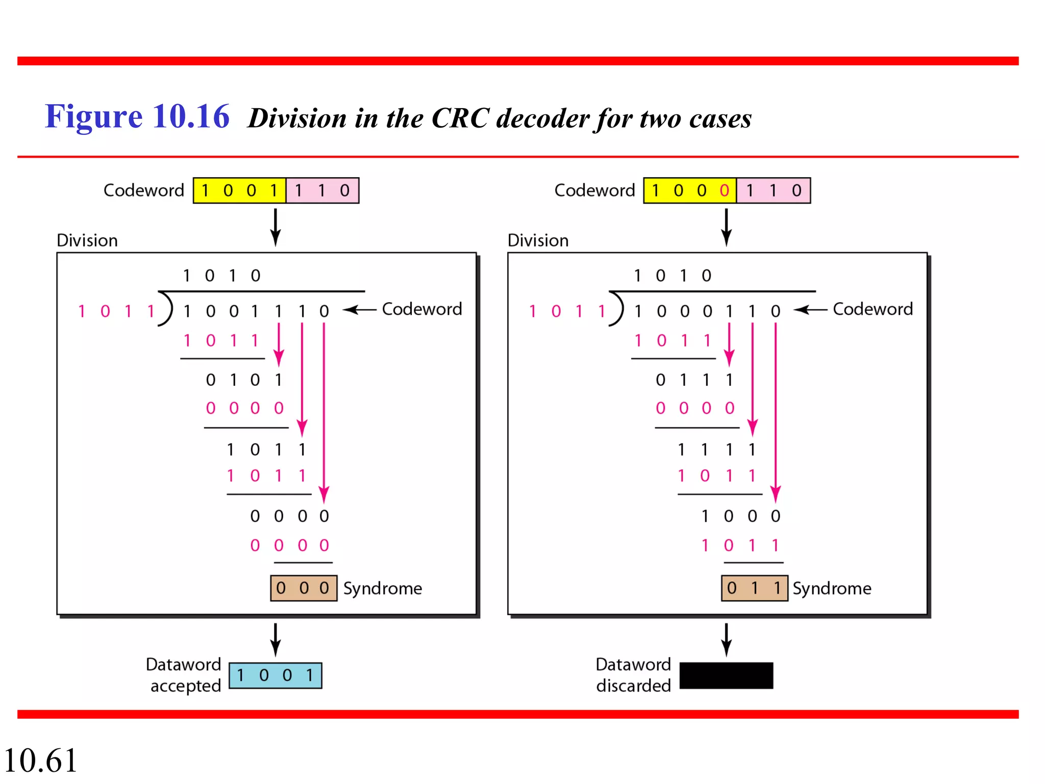
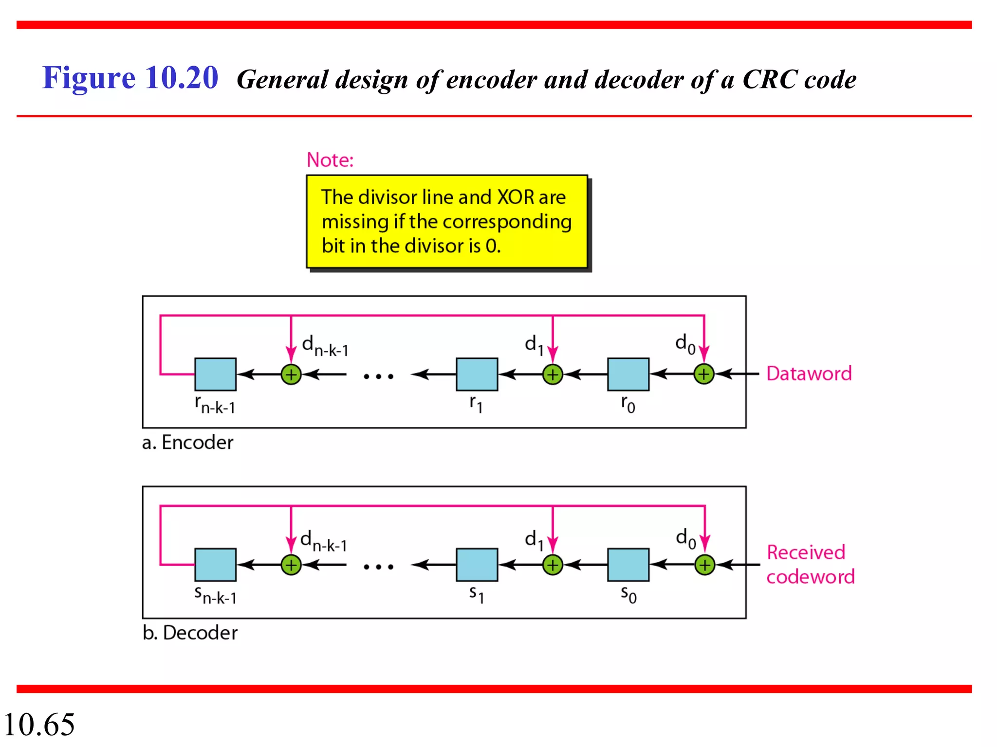
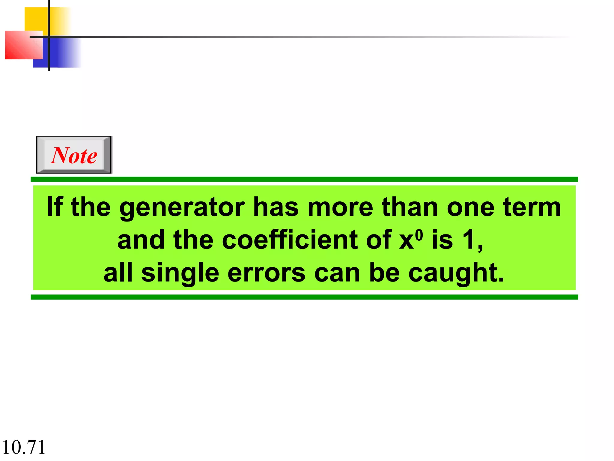
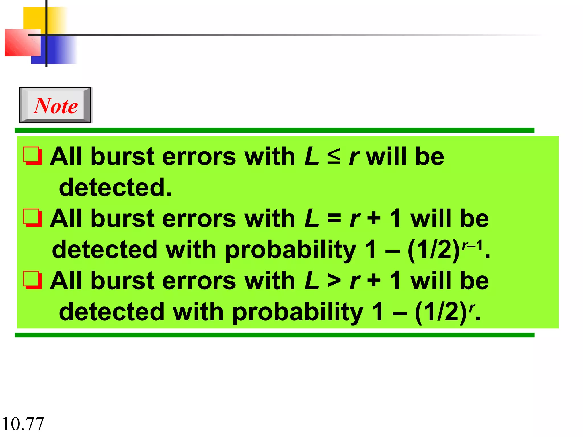
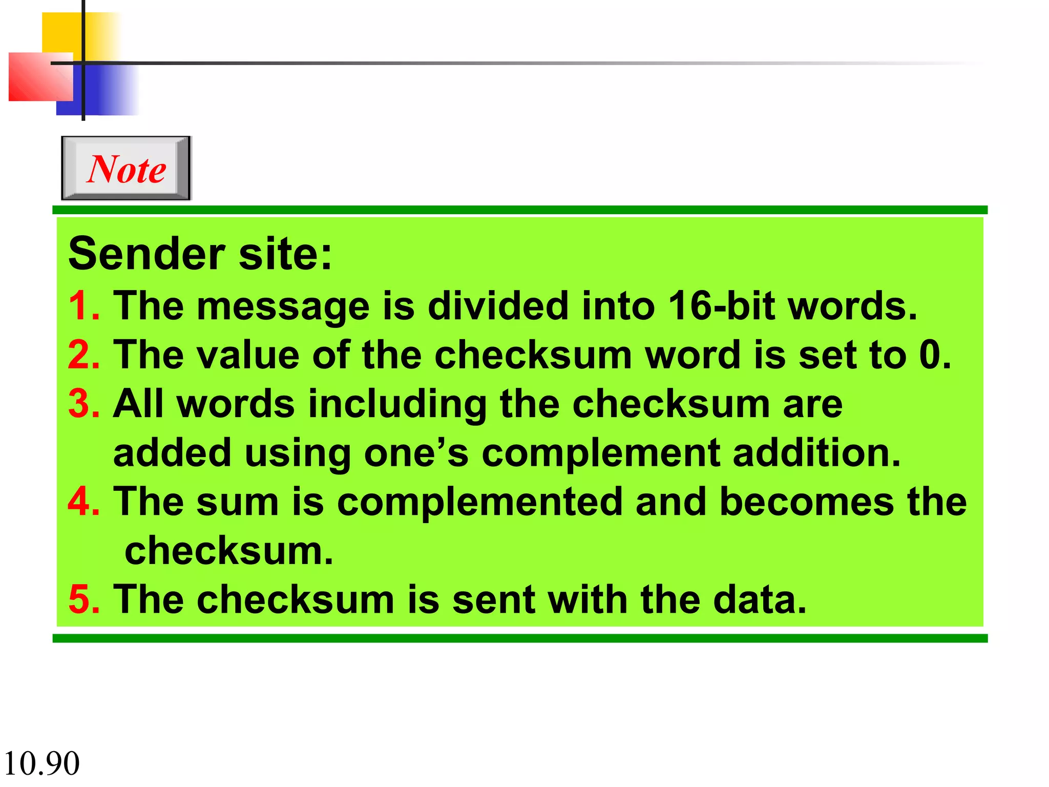
This document discusses error detection and correction in digital communications. It begins with an introduction to different types of errors that can occur like single-bit errors and burst errors. It explains that redundancy is needed to detect or correct errors. It then discusses various block coding techniques used for error detection and correction including linear block codes, cyclic codes, and cyclic redundancy checks. Specific error correcting codes like Hamming codes and parity checks are explained through examples. The key aspects of error detection capability, minimum Hamming distance, and generator polynomials in cyclic codes are covered.
How were the first error correcting codes constructed? A historical introduct...PadmaGadiyar
Hamming's original construction has been recast into symbolic form. This leads to an elementary historical route to the theory of error correcting codes. The talk is going to be historical and pedagogical in nature
Error Detection and correction concepts in Data communication and networksNt Arvind
single bit , burst error detection and correction in data communication networks , block coding ( hamming code , simple parity check code , Cyclic redundancy check-CRC , checksum , internet checksum etc
This presentation covers the type of errors during data transmission on a network. It also explains the strategies needed to detect and correct errors during data transmission. Error occurs when user receives unexpected data that was changed during transmission. There are two types of errors: Single bit error and Burst Error.
SYBSC IT COMPUTER NETWORKS UNIT II Error Detection and CorrectionArti Parab Academics
Introduction to the Data Link Layer: Link layer addressing, Data Link Layer Design Issues, Error detection and correction, block coding, cyclic codes, checksum, forward error correction, error correcting codes, error detecting codes.
Understanding Inductive Bias in Machine LearningSUTEJAS
This presentation explores the concept of inductive bias in machine learning. It explains how algorithms come with built-in assumptions and preferences that guide the learning process. You'll learn about the different types of inductive bias and how they can impact the performance and generalizability of machine learning models.
The presentation also covers the positive and negative aspects of inductive bias, along with strategies for mitigating potential drawbacks. We'll explore examples of how bias manifests in algorithms like neural networks and decision trees.
By understanding inductive bias, you can gain valuable insights into how machine learning models work and make informed decisions when building and deploying them.
Hybrid optimization of pumped hydro system and solar- Engr. Abdul-Azeez.pdffxintegritypublishin
Advancements in technology unveil a myriad of electrical and electronic breakthroughs geared towards efficiently harnessing limited resources to meet human energy demands. The optimization of hybrid solar PV panels and pumped hydro energy supply systems plays a pivotal role in utilizing natural resources effectively. This initiative not only benefits humanity but also fosters environmental sustainability. The study investigated the design optimization of these hybrid systems, focusing on understanding solar radiation patterns, identifying geographical influences on solar radiation, formulating a mathematical model for system optimization, and determining the optimal configuration of PV panels and pumped hydro storage. Through a comparative analysis approach and eight weeks of data collection, the study addressed key research questions related to solar radiation patterns and optimal system design. The findings highlighted regions with heightened solar radiation levels, showcasing substantial potential for power generation and emphasizing the system's efficiency. Optimizing system design significantly boosted power generation, promoted renewable energy utilization, and enhanced energy storage capacity. The study underscored the benefits of optimizing hybrid solar PV panels and pumped hydro energy supply systems for sustainable energy usage. Optimizing the design of solar PV panels and pumped hydro energy supply systems as examined across diverse climatic conditions in a developing country, not only enhances power generation but also improves the integration of renewable energy sources and boosts energy storage capacities, particularly beneficial for less economically prosperous regions. Additionally, the study provides valuable insights for advancing energy research in economically viable areas. Recommendations included conducting site-specific assessments, utilizing advanced modeling tools, implementing regular maintenance protocols, and enhancing communication among system components.
Harnessing WebAssembly for Real-time Stateless Streaming PipelinesChristina Lin
Traditionally, dealing with real-time data pipelines has involved significant overhead, even for straightforward tasks like data transformation or masking. However, in this talk, we’ll venture into the dynamic realm of WebAssembly (WASM) and discover how it can revolutionize the creation of stateless streaming pipelines within a Kafka (Redpanda) broker. These pipelines are adept at managing low-latency, high-data-volume scenarios.
Industrial Training at Shahjalal Fertilizer Company Limited (SFCL)MdTanvirMahtab2
This presentation is about the working procedure of Shahjalal Fertilizer Company Limited (SFCL). A Govt. owned Company of Bangladesh Chemical Industries Corporation under Ministry of Industries.
Student information management system project report ii.pdfKamal Acharya
Our project explains about the student management. This project mainly explains the various actions related to student details. This project shows some ease in adding, editing and deleting the student details. It also provides a less time consuming process for viewing, adding, editing and deleting the marks of the students.
Immunizing Image Classifiers Against Localized Adversary Attacksgerogepatton
This paper addresses the vulnerability of deep learning models, particularly convolutional neural networks
(CNN)s, to adversarial attacks and presents a proactive training technique designed to counter them. We
introduce a novel volumization algorithm, which transforms 2D images into 3D volumetric representations.
When combined with 3D convolution and deep curriculum learning optimization (CLO), itsignificantly improves
the immunity of models against localized universal attacks by up to 40%. We evaluate our proposed approach
using contemporary CNN architectures and the modified Canadian Institute for Advanced Research (CIFAR-10
and CIFAR-100) and ImageNet Large Scale Visual Recognition Challenge (ILSVRC12) datasets, showcasing
accuracy improvements over previous techniques. The results indicate that the combination of the volumetric
input and curriculum learning holds significant promise for mitigating adversarial attacks without necessitating
adversary training.
Welcome to WIPAC Monthly the magazine brought to you by the LinkedIn Group Water Industry Process Automation & Control.
In this month's edition, along with this month's industry news to celebrate the 13 years since the group was created we have articles including
A case study of the used of Advanced Process Control at the Wastewater Treatment works at Lleida in Spain
A look back on an article on smart wastewater networks in order to see how the industry has measured up in the interim around the adoption of Digital Transformation in the Water Industry.
6th International Conference on Machine Learning & Applications (CMLA 2024)ClaraZara1
6th International Conference on Machine Learning & Applications (CMLA 2024) will provide an excellent international forum for sharing knowledge and results in theory, methodology and applications of on Machine Learning & Applications.
HEAP SORT ILLUSTRATED WITH HEAPIFY, BUILD HEAP FOR DYNAMIC ARRAYS.
Heap sort is a comparison-based sorting technique based on Binary Heap data structure. It is similar to the selection sort where we first find the minimum element and place the minimum element at the beginning. Repeat the same process for the remaining elements.
The Internet of Things (IoT) is a revolutionary concept that connects everyday objects and devices to the internet, enabling them to communicate, collect, and exchange data. Imagine a world where your refrigerator notifies you when you’re running low on groceries, or streetlights adjust their brightness based on traffic patterns – that’s the power of IoT. In essence, IoT transforms ordinary objects into smart, interconnected devices, creating a network of endless possibilities.
Here is a blog on the role of electrical and electronics engineers in IOT. Let's dig in!!!!
For more such content visit: https://nttftrg.com/
2. 10.2
Data can be corrupted
during transmission.
Some applications require that
errors be detected and corrected.
Note
3. 10.3
10-1 INTRODUCTION10-1 INTRODUCTION
Let us first discuss some issues related, directly orLet us first discuss some issues related, directly or
indirectly, to error detection and correction.indirectly, to error detection and correction.
Types of Errors
Redundancy
Detection Versus Correction
Forward Error Correction Versus Retransmission
Coding
Modular Arithmetic
Topics discussed in this section:Topics discussed in this section:
13. 10.13
10-2 BLOCK CODING10-2 BLOCK CODING
In block coding, we divide our message into blocks,In block coding, we divide our message into blocks,
each of k bits, calledeach of k bits, called datawordsdatawords. We add r redundant. We add r redundant
bits to each block to make the length n = k + r. Thebits to each block to make the length n = k + r. The
resulting n-bit blocks are calledresulting n-bit blocks are called codewordscodewords..
Error Detection
Error Correction
Hamming Distance
Minimum Hamming Distance
Topics discussed in this section:Topics discussed in this section:
15. 10.15
The 4B/5B block coding discussed in Chapter 4 is a good
example of this type of coding. In this coding scheme,
k = 4 and n = 5. As we saw, we have 2k
= 16 datawords
and 2n
= 32 codewords. We saw that 16 out of 32
codewords are used for message transfer and the rest are
either used for other purposes or unused.
Example 10.1
17. 10.17
Let us assume that k = 2 and n = 3. Table 10.1 shows the
list of datawords and codewords. Later, we will see
how to derive a codeword from a dataword.
Assume the sender encodes the dataword 01 as 011 and
sends it to the receiver. Consider the following cases:
1. The receiver receives 011. It is a valid codeword. The
receiver extracts the dataword 01 from it.
Example 10.2
18. 10.18
2. The codeword is corrupted during transmission, and
111 is received. This is not a valid codeword and is
discarded.
3. The codeword is corrupted during transmission, and
000 is received. This is a valid codeword. The receiver
incorrectly extracts the dataword 00. Two corrupted
bits have made the error undetectable.
Example 10.2 (continued)
22. 10.22
Let us add more redundant bits to Example 10.2 to see if
the receiver can correct an error without knowing what
was actually sent. We add 3 redundant bits to the 2-bit
dataword to make 5-bit codewords. Table 10.2 shows the
datawords and codewords. Assume the dataword is 01.
The sender creates the codeword 01011. The codeword is
corrupted during transmission, and 01001 is received.
First, the receiver finds that the received codeword is not
in the table. This means an error has occurred. The
receiver, assuming that there is only 1 bit corrupted, uses
the following strategy to guess the correct dataword.
Example 10.3
23. 10.23
1. Comparing the received codeword with the first
codeword in the table (01001 versus 00000), the
receiver decides that the first codeword is not the one
that was sent because there are two different bits.
2. By the same reasoning, the original codeword cannot
be the third or fourth one in the table.
3. The original codeword must be the second one in the
table because this is the only one that differs from the
received codeword by 1 bit. The receiver replaces
01001 with 01011 and consults the table to find the
dataword 01.
Example 10.3 (continued)
25. 10.25
The Hamming distance between two
words is the number of differences
between corresponding bits.
Note
26. 10.26
Let us find the Hamming distance between two pairs of
words.
1. The Hamming distance d(000, 011) is 2 because
Example 10.4
2. The Hamming distance d(10101, 11110) is 3 because
27. 10.27
The minimum Hamming distance is the
smallest Hamming distance between
all possible pairs in a set of words.
Note
28. 10.28
Find the minimum Hamming distance of the coding
scheme in Table 10.1.
Solution
We first find all Hamming distances.
Example 10.5
The dmin in this case is 2.
29. 10.29
Find the minimum Hamming distance of the coding
scheme in Table 10.2.
Solution
We first find all the Hamming distances.
The dmin in this case is 3.
Example 10.6
30. 10.30
To guarantee the detection of up to s
errors in all cases, the minimum
Hamming distance in a block
code must be dmin = s + 1.
Note
31. 10.31
The minimum Hamming distance for our first code
scheme (Table 10.1) is 2. This code guarantees detection
of only a single error. For example, if the third codeword
(101) is sent and one error occurs, the received codeword
does not match any valid codeword. If two errors occur,
however, the received codeword may match a valid
codeword and the errors are not detected.
Example 10.7
32. 10.32
Our second block code scheme (Table 10.2) has dmin = 3.
This code can detect up to two errors. Again, we see that
when any of the valid codewords is sent, two errors create
a codeword which is not in the table of valid codewords.
The receiver cannot be fooled.
However, some combinations of three errors change a
valid codeword to another valid codeword. The receiver
accepts the received codeword and the errors are
undetected.
Example 10.8
35. 10.35
To guarantee correction of up to t errors
in all cases, the minimum Hamming
distance in a block code
must be dmin = 2t + 1.
Note
36. 10.36
A code scheme has a Hamming distance dmin = 4. What is
the error detection and correction capability of this
scheme?
Solution
This code guarantees the detection of up to three errors
(s = 3), but it can correct up to one error. In other words,
if this code is used for error correction, part of its capability
is wasted. Error correction codes need to have an odd
minimum distance (3, 5, 7, . . . ).
Example 10.9
37. 10.37
10-3 LINEAR BLOCK CODES10-3 LINEAR BLOCK CODES
Almost all block codes used today belong to a subsetAlmost all block codes used today belong to a subset
calledcalled linear block codeslinear block codes. A linear block code is a code. A linear block code is a code
in which the exclusive OR (addition modulo-2) of twoin which the exclusive OR (addition modulo-2) of two
valid codewords creates another valid codeword.valid codewords creates another valid codeword.
Minimum Distance for Linear Block Codes
Some Linear Block Codes
Topics discussed in this section:Topics discussed in this section:
38. 10.38
In a linear block code, the exclusive OR
(XOR) of any two valid codewords
creates another valid codeword.
Note
39. 10.39
Let us see if the two codes we defined in Table 10.1 and
Table 10.2 belong to the class of linear block codes.
1. The scheme in Table 10.1 is a linear block code
because the result of XORing any codeword with any
other codeword is a valid codeword. For example, the
XORing of the second and third codewords creates the
fourth one.
2. The scheme in Table 10.2 is also a linear block code.
We can create all four codewords by XORing two
other codewords.
Example 10.10
40. 10.40
In our first code (Table 10.1), the numbers of 1s in the
nonzero codewords are 2, 2, and 2. So the minimum
Hamming distance is dmin = 2. In our second code (Table
10.2), the numbers of 1s in the nonzero codewords are 3,
3, and 4. So in this code we have dmin = 3.
Example 10.11
41. 10.41
A simple parity-check code is a
single-bit error-detecting
code in which
n = k + 1 with dmin = 2.
Note
44. 10.44
Let us look at some transmission scenarios. Assume the
sender sends the dataword 1011. The codeword created
from this dataword is 10111, which is sent to the receiver.
We examine five cases:
1. No error occurs; the received codeword is 10111. The
syndrome is 0. The dataword 1011 is created.
2. One single-bit error changes a1 . The received
codeword is 10011. The syndrome is 1. No dataword
is created.
3. One single-bit error changes r0 . The received codeword
is 10110. The syndrome is 1. No dataword is created.
Example 10.12
45. 10.45
4. An error changes r0 and a second error changes a3 .
The received codeword is 00110. The syndrome is 0.
The dataword 0011 is created at the receiver. Note that
here the dataword is wrongly created due to the
syndrome value.
5. Three bits—a3, a2, and a1—are changed by errors.
The received codeword is 01011. The syndrome is 1.
The dataword is not created. This shows that the simple
parity check, guaranteed to detect one single error, can
also find any odd number of errors.
Example 10.12 (continued)
54. 10.54
Let us trace the path of three datawords from the sender
to the destination:
1. The dataword 0100 becomes the codeword 0100011.
The codeword 0100011 is received. The syndrome is
000, the final dataword is 0100.
2. The dataword 0111 becomes the codeword 0111001.
The syndrome is 011. After flipping b2 (changing the 1
to 0), the final dataword is 0111.
3. The dataword 1101 becomes the codeword 1101000.
The syndrome is 101. After flipping b0, we get 0000,
the wrong dataword. This shows that our code cannot
correct two errors.
Example 10.13
55. 10.55
We need a dataword of at least 7 bits. Calculate values of
k and n that satisfy this requirement.
Solution
We need to make k = n m greater than or equal to 7, or−
2m 1 m 7.− − ≥
1. If we set m = 3, the result is n = 23 1 and k = 7 3,− −
or 4, which is not acceptable.
2. If we set m = 4, then n = 24 1 = 15 and k = 15 4 =− −
11, which satisfies the condition. So the code is
Example 10.14
C(15, 11)
57. 10.57
10-4 CYCLIC CODES10-4 CYCLIC CODES
Cyclic codesCyclic codes are special linear block codes with oneare special linear block codes with one
extra property. In a cyclic code, if a codeword isextra property. In a cyclic code, if a codeword is
cyclically shifted (rotated), the result is anothercyclically shifted (rotated), the result is another
codeword.codeword.
Cyclic Redundancy Check
Hardware Implementation
Polynomials
Cyclic Code Analysis
Advantages of Cyclic Codes
Other Cyclic Codes
Topics discussed in this section:Topics discussed in this section:
68. 10.68
The divisor in a cyclic code is normally
called the generator polynomial
or simply the generator.
Note
69. 10.69
In a cyclic code,
If s(x) ≠ 0, one or more bits is corrupted.
If s(x) = 0, either
a. No bit is corrupted. or
b. Some bits are corrupted, but the
decoder failed to detect them.
Note
70. 10.70
In a cyclic code, those e(x) errors that
are divisible by g(x) are not caught.
Note
71. 10.71
If the generator has more than one term
and the coefficient of x0
is 1,
all single errors can be caught.
Note
72. 10.72
Which of the following g(x) values guarantees that a
single-bit error is caught? For each case, what is the
error that cannot be caught?
a. x + 1 b. x3
c. 1
Solution
a. No xi
can be divisible by x + 1. Any single-bit error can
be caught.
b. If i is equal to or greater than 3, xi
is divisible by g(x).
All single-bit errors in positions 1 to 3 are caught.
c. All values of i make xi
divisible by g(x). No single-bit
error can be caught. This g(x) is useless.
Example 10.15
74. 10.74
If a generator cannot divide xt
+ 1
(t between 0 and n – 1),
then all isolated double errors
can be detected.
Note
75. 10.75
Find the status of the following generators related to two
isolated, single-bit errors.
a. x + 1 b. x4
+ 1 c. x7
+ x6
+ 1 d. x15
+ x14
+ 1
Solution
a. This is a very poor choice for a generator. Any two
errors next to each other cannot be detected.
b. This generator cannot detect two errors that are four
positions apart.
c. This is a good choice for this purpose.
d. This polynomial cannot divide xt
+ 1 if t is less than
32,768. A codeword with two isolated errors up to
32,768 bits apart can be detected by this generator.
Example 10.16
76. 10.76
A generator that contains a factor of
x + 1 can detect all odd-numbered
errors.
Note
77. 10.77
❏ All burst errors with L ≤ r will be
detected.
❏ All burst errors with L = r + 1 will be
detected with probability 1 – (1/2)r–1
.
❏ All burst errors with L > r + 1 will be
detected with probability 1 – (1/2)r
.
Note
78. 10.78
Find the suitability of the following generators in relation
to burst errors of different lengths.
a. x6
+ 1 b. x18
+ x7
+ x + 1 c. x32
+ x23
+ x7
+ 1
Solution
a. This generator can detect all burst errors with a length
less than or equal to 6 bits; 3 out of 100 burst errors
with length 7 will slip by; 16 out of 1000 burst errors of
length 8 or more will slip by.
Example 10.17
79. 10.79
b. This generator can detect all burst errors with a length
less than or equal to 18 bits; 8 out of 1 million burst
errors with length 19 will slip by; 4 out of 1 million
burst errors of length 20 or more will slip by.
c. This generator can detect all burst errors with a length
less than or equal to 32 bits; 5 out of 10 billion burst
errors with length 33 will slip by; 3 out of 10 billion
burst errors of length 34 or more will slip by.
Example 10.17 (continued)
80. 10.80
A good polynomial generator needs to
have the following characteristics:
1. It should have at least two terms.
2. The coefficient of the term x0
should
be 1.
3. It should not divide xt
+ 1, for t
between 2 and n − 1.
4. It should have the factor x + 1.
Note
82. 10.82
10-5 CHECKSUM10-5 CHECKSUM
The last error detection method we discuss here isThe last error detection method we discuss here is
called the checksum. The checksum is used in thecalled the checksum. The checksum is used in the
Internet by several protocols although not at the dataInternet by several protocols although not at the data
link layer. However, we briefly discuss it here tolink layer. However, we briefly discuss it here to
complete our discussion on error checkingcomplete our discussion on error checking
Idea
One’s Complement
Internet Checksum
Topics discussed in this section:Topics discussed in this section:
83. 10.83
Suppose our data is a list of five 4-bit numbers that we
want to send to a destination. In addition to sending these
numbers, we send the sum of the numbers. For example,
if the set of numbers is (7, 11, 12, 0, 6), we send (7, 11, 12,
0, 6, 36), where 36 is the sum of the original numbers.
The receiver adds the five numbers and compares the
result with the sum. If the two are the same, the receiver
assumes no error, accepts the five numbers, and discards
the sum. Otherwise, there is an error somewhere and the
data are not accepted.
Example 10.18
84. 10.84
We can make the job of the receiver easier if we send the
negative (complement) of the sum, called the checksum.
In this case, we send (7, 11, 12, 0, 6, −36). The receiver
can add all the numbers received (including the
checksum). If the result is 0, it assumes no error;
otherwise, there is an error.
Example 10.19
85. 10.85
How can we represent the number 21 in one’s
complement arithmetic using only four bits?
Solution
The number 21 in binary is 10101 (it needs five bits). We
can wrap the leftmost bit and add it to the four rightmost
bits. We have (0101 + 1) = 0110 or 6.
Example 10.20
86. 10.86
How can we represent the number −6 in one’s
complement arithmetic using only four bits?
Solution
In one’s complement arithmetic, the negative or
complement of a number is found by inverting all bits.
Positive 6 is 0110; negative 6 is 1001. If we consider only
unsigned numbers, this is 9. In other words, the
complement of 6 is 9. Another way to find the
complement of a number in one’s complement arithmetic
is to subtract the number from 2n
1 (16 1 in this case).− −
Example 10.21
87. 10.87
Let us redo Exercise 10.19 using one’s complement
arithmetic. Figure 10.24 shows the process at the sender
and at the receiver. The sender initializes the checksum
to 0 and adds all data items and the checksum (the
checksum is considered as one data item and is shown in
color). The result is 36. However, 36 cannot be expressed
in 4 bits. The extra two bits are wrapped and added with
the sum to create the wrapped sum value 6. In the figure,
we have shown the details in binary. The sum is then
complemented, resulting in the checksum value 9 (15 − 6
= 9). The sender now sends six data items to the receiver
including the checksum 9.
Example 10.22
88. 10.88
The receiver follows the same procedure as the sender. It
adds all data items (including the checksum); the result
is 45. The sum is wrapped and becomes 15. The wrapped
sum is complemented and becomes 0. Since the value of
the checksum is 0, this means that the data is not
corrupted. The receiver drops the checksum and keeps
the other data items. If the checksum is not zero, the
entire packet is dropped.
Example 10.22 (continued)
90. 10.90
Sender site:
1. The message is divided into 16-bit words.
2. The value of the checksum word is set to 0.
3. All words including the checksum are
added using one’s complement addition.
4. The sum is complemented and becomes the
checksum.
5. The checksum is sent with the data.
Note
91. 10.91
Receiver site:
1. The message (including checksum) is
divided into 16-bit words.
2. All words are added using one’s
complement addition.
3. The sum is complemented and becomes the
new checksum.
4. If the value of checksum is 0, the message
is accepted; otherwise, it is rejected.
Note
92. 10.92
Let us calculate the checksum for a text of 8 characters
(“Forouzan”). The text needs to be divided into 2-byte
(16-bit) words. We use ASCII (see Appendix A) to change
each byte to a 2-digit hexadecimal number. For example,
F is represented as 0x46 and o is represented as 0x6F.
Figure 10.25 shows how the checksum is calculated at the
sender and receiver sites. In part a of the figure, the value
of partial sum for the first column is 0x36. We keep the
rightmost digit (6) and insert the leftmost digit (3) as the
carry in the second column. The process is repeated for
each column. Note that if there is any corruption, the
checksum recalculated by the receiver is not all 0s. We
leave this an exercise.
Example 10.23