Downloaded 130 times

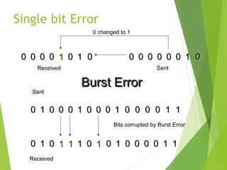
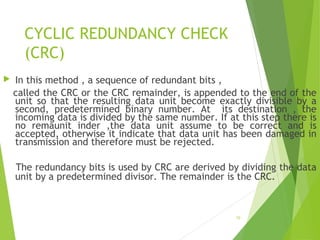

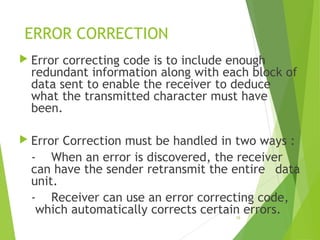
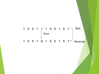
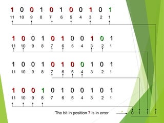

The document discusses error detection and correction in data transmission, highlighting the importance of ensuring reliable communication by identifying and fixing errors. It describes types of errors, such as single bit and burst errors, and outlines methods for error detection, including various redundancy checks like CRC. Furthermore, it explains error correction techniques, particularly Hamming code, allowing receivers to deduce and correct errors using redundancy bits.