This document provides an overview of antennas, including:
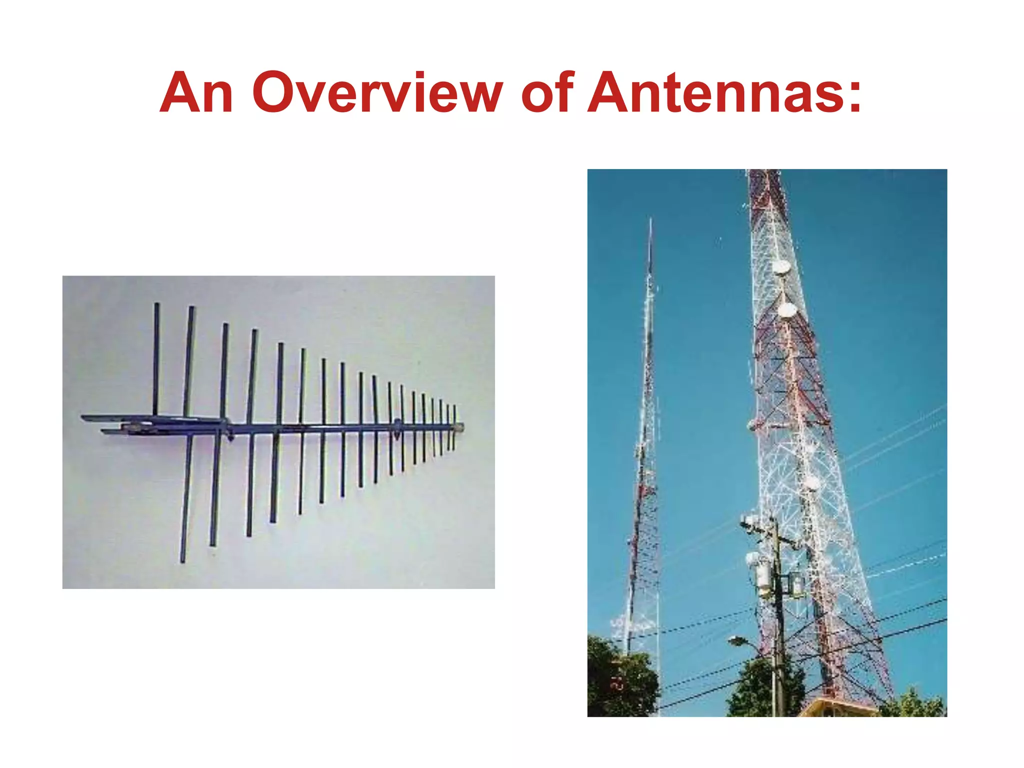
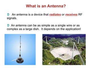
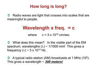
- Antennas are devices that radiate or receive radio frequency (RF) signals. Common antennas range from simple single wires to complex dishes.
- Antenna behavior is the same whether transmitting or receiving due to the reciprocity principle. However, how it's used and the attached electronics determine transmission or reception.
- Important antenna characteristics that impact performance include radiated/received power, gain, wavelength, polarization, distance, and bandwidth. The Friis transmission formula relates these factors for antenna systems.

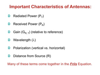
![The FRIIS Transmission Formula:
PR = [PT GT GR 2] / [4R]2
From this it can be seen that received antenna
power increases with
1. Transmitted power
2. Gains (directionality relative to each other)
3. Wavelength
And it decreases with distance2.](https://image.slidesharecdn.com/lec-antennas-230216083100-6b5af05f/85/lec-antennas-ppt-9-320.jpg)