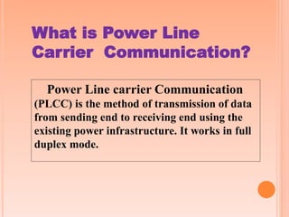
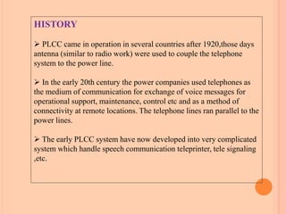
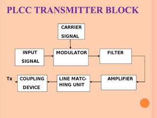
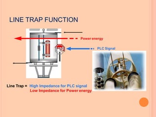
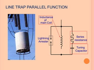
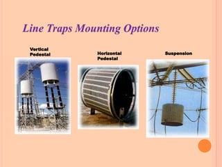
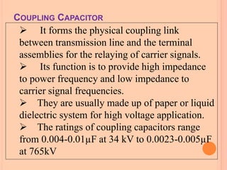
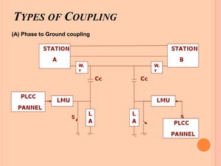
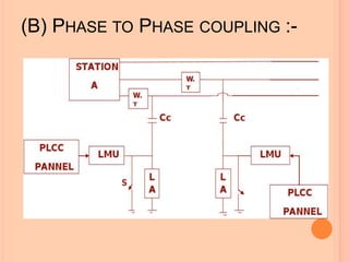
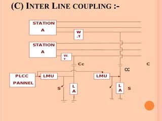
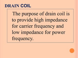
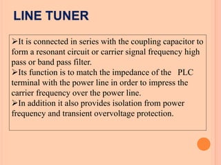
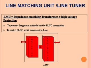
POWER LINE CARRIER
COMMUNICATION
PRESENTED
BY
D.LAVANYA
Power Line carrier Communication
(PLCC) is the method of transmission of data
from sending end to receiving end using the
existing power infrastructure. It works in full
duplex mode.
What is Power Line
Carrier Communication?
HISTORY
 PLCC came in operation in several countries after 1920,those days
antenna (similar to radio work) were used to couple the telephone
system to the power line.
 In the early 20th century the power companies used telephones as
the medium of communication for exchange of voice messages for
operational support, maintenance, control etc and as a method of
connectivity at remote locations. The telephone lines ran parallel to the
power lines.
 The early PLCC system have now developed into very complicated
system which handle speech communication teleprinter, tele signaling
,etc.
GENERAL BLOCK DIAGRAM OF PLCC
Power Line
(50Hz)
C.C
RF carrier
(40-500kHz)
RTa
U
Transmission line
L.T
PAX
PLCC TERMINAL
(ABB-ETL41)
Power Line Carrier Communication System
PLCC TRANSMITTER BLOCK
PLCC RECEIVER BLOCK
PLCC system consists of three parts:
The terminal assemblies include the
receivers transmitters and protective relays.
The coupling equipment is the combination
of line tuner, coupling capacitor and the wave
or line trap.
The 50/60 Hz power transmission line
serves as path for relaying data in the PLCC
bandwidth.
CONSTRUCTION
LINE TRAP/WAVE TRAP
 It is a parallel L-C tank filter or band-stop filter
connected in series with the transmission line.
 It presents high impedance to carrier signal
frequencies and very low impedance to the power
frequency consists of main coil, tunning device,
protective device.
MAIN COIL
An inductor that is connected directly to the high
voltage power line carries power frequency.
TUNNING DEVICE
It may be a capacitor or a combination of capacitor, inductor
and resistor, connected across the main coil in order to tune the
line trap to the desired blocking frequency.
PROTECTIVE DEVICE
 It is usually a gap type surge arrester used to protect the
line trap from damage due to transient over-voltages.
 The line trap or wave trap prevents unwanted loss of
carrier signal power and also prevents carrier signal transmission
to adjacent power lines. Line traps or wave traps are available for
narrow-band and wide-band carrier frequency blocking
applications.
Line Trap = High Impedance for PLC signal
Low Impedance for Power energy
Power energy
PLC Signal
LINE TRAP FUNCTION
Inductance
of
main Coil
Lightning
Arrester
Series
resistance
Tuning
Capacitor
LINE TRAP PARALLEL FUNCTION
Vertical
Pedestal Horizontal
Pedestal
Suspension
Line Traps Mounting Options
 It forms the physical coupling link
between transmission line and the terminal
assemblies for the relaying of carrier signals.
 Its function is to provide high impedance
to power frequency and low impedance to
carrier signal frequencies.
 They are usually made up of paper or liquid
dielectric system for high voltage application.
 The ratings of coupling capacitors range
from 0.004-0.01µF at 34 kV to 0.0023-0.005µF
at 765kV
COUPLING CAPACITOR
Local substation
To remote
substation
Coupling
Capacitor
Line
Matching
Unit
PLC terminalAXSWDED3
Coaxial
•Transformer(s)
•BusBar
Line
Trap
The PLC
signal is
routed to
H.V Line
The PLC
signal is
not
absorbed
by the
substation
COUPLING SCHEME
TYPES OF COUPLING
(A) Phase to Ground coupling
(B) PHASE TO PHASE COUPLING :-
(C) INTER LINE COUPLING :-
DRAIN COIL
The purpose of drain coil is
to provide high impedance
for carrier frequency and
low impedance for power
frequency.
LINE TUNER
It is connected in series with the coupling capacitor to
form a resonant circuit or carrier signal frequency high
pass or band pass filter.
Its function is to match the impedance of the PLC
terminal with the power line in order to impress the
carrier frequency over the power line.
In addition it also provides isolation from power
frequency and transient overvoltage protection.
M
A
t
c
h
i
n
g
+
P
R
O
T
E
C
T
I
O
N
LMU
LINE MATCHING UNIT /LINE TUNER
PLCC Panel ( type: ABB ETL 41/42)
Cabinet
Module
Typical PLCC Installation
MS = Master station
PAX = Private automatic exchange
PR = Protection relay
PC = Computer
M = Modem
ETL
ETL
LT
LT
FAX
FAX
PR PC MS PAX FAX
M
PR PC RTU FAX
M
PR= Protection relay
FAX = Facsimileequipment
M = Modem
RTU = Remote terminalunit
cc cc
Batteries
 PLCC work on rectified AC or main supply, when supply goes off, we
make use of a device for proper functioning of PLCC called battery
charger.
 This is the device that provide supply to the PLCC
equipment for uninterrupted working.
 It provide DC to the panel by battery.
ADVANTAGES
22
1. No separate wires are needed for communication purposes, as the power
lines themselves carry power as well as communication signals. Hence the
cost is less.
2 Power lines have appreciably higher mechanical strength compared with
ordinary lines. They would normally remain unaffected under the conditions,
which might seriously damage telephone lines.
3. Power lines usually provide the shortest route between the power stations.
4. Power lines have large cross-sectional area resulting in very low resistance
per unit length. Consequently carrier signals suffer much less attenuation
than when they travel on telephone lines of equal lengths.
5.Power lines are well insulated to provide only negligible leakage between
conductors and ground even in adverse weather conditions.
6.Largest spacing between conductors reduces capacitance, which results in
smaller attenuation at high frequencies. The large spacing also reduces the
cross talk to a considerable extent.
DISADVANTAGES
Proper care has to be taken to guard carrier equipment and
persons using them against high voltages and currents on the lines.
Reflections are produced on lines connected to high voltage lines.
This increases attenuation and creates problem.
 High
carrier
voltage lines have transformer connections, attenuate
currents. Sub-station equipments adversely affect the
carrier currents.
 Noise introduced by power lines is far more than in case of
telephone lines. This is due to the noise generated by discharge
across insulators, corona and switching processes.
 It is obvious than effective power lines carrier system must
overcome these difficulties.
APPLICATION
PLCC unit provide five type of operation:
 TELEPHONE FACILITES
 COMPRESSOR & EXPANDER
 EMERGENCY CALL
 SIGNAL BOOSTING
 SUPERVISION & ALARMS
THANK
YOU

power line carrier communication

  • 1.
  • 2.
    Power Line carrierCommunication (PLCC) is the method of transmission of data from sending end to receiving end using the existing power infrastructure. It works in full duplex mode. What is Power Line Carrier Communication?
  • 3.
    HISTORY  PLCC camein operation in several countries after 1920,those days antenna (similar to radio work) were used to couple the telephone system to the power line.  In the early 20th century the power companies used telephones as the medium of communication for exchange of voice messages for operational support, maintenance, control etc and as a method of connectivity at remote locations. The telephone lines ran parallel to the power lines.  The early PLCC system have now developed into very complicated system which handle speech communication teleprinter, tele signaling ,etc.
  • 4.
  • 5.
    Power Line (50Hz) C.C RF carrier (40-500kHz) RTa U Transmissionline L.T PAX PLCC TERMINAL (ABB-ETL41) Power Line Carrier Communication System
  • 6.
  • 7.
  • 8.
    PLCC system consistsof three parts: The terminal assemblies include the receivers transmitters and protective relays. The coupling equipment is the combination of line tuner, coupling capacitor and the wave or line trap. The 50/60 Hz power transmission line serves as path for relaying data in the PLCC bandwidth. CONSTRUCTION
  • 9.
    LINE TRAP/WAVE TRAP It is a parallel L-C tank filter or band-stop filter connected in series with the transmission line.  It presents high impedance to carrier signal frequencies and very low impedance to the power frequency consists of main coil, tunning device, protective device. MAIN COIL An inductor that is connected directly to the high voltage power line carries power frequency.
  • 10.
    TUNNING DEVICE It maybe a capacitor or a combination of capacitor, inductor and resistor, connected across the main coil in order to tune the line trap to the desired blocking frequency. PROTECTIVE DEVICE  It is usually a gap type surge arrester used to protect the line trap from damage due to transient over-voltages.  The line trap or wave trap prevents unwanted loss of carrier signal power and also prevents carrier signal transmission to adjacent power lines. Line traps or wave traps are available for narrow-band and wide-band carrier frequency blocking applications.
  • 11.
    Line Trap =High Impedance for PLC signal Low Impedance for Power energy Power energy PLC Signal LINE TRAP FUNCTION
  • 12.
  • 13.
  • 14.
     It formsthe physical coupling link between transmission line and the terminal assemblies for the relaying of carrier signals.  Its function is to provide high impedance to power frequency and low impedance to carrier signal frequencies.  They are usually made up of paper or liquid dielectric system for high voltage application.  The ratings of coupling capacitors range from 0.004-0.01µF at 34 kV to 0.0023-0.005µF at 765kV COUPLING CAPACITOR
  • 15.
    Local substation To remote substation Coupling Capacitor Line Matching Unit PLCterminalAXSWDED3 Coaxial •Transformer(s) •BusBar Line Trap The PLC signal is routed to H.V Line The PLC signal is not absorbed by the substation COUPLING SCHEME
  • 16.
    TYPES OF COUPLING (A)Phase to Ground coupling
  • 17.
    (B) PHASE TOPHASE COUPLING :-
  • 18.
    (C) INTER LINECOUPLING :-
  • 19.
    DRAIN COIL The purposeof drain coil is to provide high impedance for carrier frequency and low impedance for power frequency.
  • 20.
    LINE TUNER It isconnected in series with the coupling capacitor to form a resonant circuit or carrier signal frequency high pass or band pass filter. Its function is to match the impedance of the PLC terminal with the power line in order to impress the carrier frequency over the power line. In addition it also provides isolation from power frequency and transient overvoltage protection.
  • 21.
  • 22.
    PLCC Panel (type: ABB ETL 41/42) Cabinet Module
  • 23.
    Typical PLCC Installation MS= Master station PAX = Private automatic exchange PR = Protection relay PC = Computer M = Modem ETL ETL LT LT FAX FAX PR PC MS PAX FAX M PR PC RTU FAX M PR= Protection relay FAX = Facsimileequipment M = Modem RTU = Remote terminalunit cc cc
  • 24.
    Batteries  PLCC workon rectified AC or main supply, when supply goes off, we make use of a device for proper functioning of PLCC called battery charger.  This is the device that provide supply to the PLCC equipment for uninterrupted working.  It provide DC to the panel by battery.
  • 25.
    ADVANTAGES 22 1. No separatewires are needed for communication purposes, as the power lines themselves carry power as well as communication signals. Hence the cost is less. 2 Power lines have appreciably higher mechanical strength compared with ordinary lines. They would normally remain unaffected under the conditions, which might seriously damage telephone lines. 3. Power lines usually provide the shortest route between the power stations. 4. Power lines have large cross-sectional area resulting in very low resistance per unit length. Consequently carrier signals suffer much less attenuation than when they travel on telephone lines of equal lengths. 5.Power lines are well insulated to provide only negligible leakage between conductors and ground even in adverse weather conditions. 6.Largest spacing between conductors reduces capacitance, which results in smaller attenuation at high frequencies. The large spacing also reduces the cross talk to a considerable extent.
  • 26.
    DISADVANTAGES Proper care hasto be taken to guard carrier equipment and persons using them against high voltages and currents on the lines. Reflections are produced on lines connected to high voltage lines. This increases attenuation and creates problem.  High carrier voltage lines have transformer connections, attenuate currents. Sub-station equipments adversely affect the carrier currents.  Noise introduced by power lines is far more than in case of telephone lines. This is due to the noise generated by discharge across insulators, corona and switching processes.  It is obvious than effective power lines carrier system must overcome these difficulties.
  • 27.
    APPLICATION PLCC unit providefive type of operation:  TELEPHONE FACILITES  COMPRESSOR & EXPANDER  EMERGENCY CALL  SIGNAL BOOSTING  SUPERVISION & ALARMS
  • 28.