Downloaded 220 times


![References:
[1] R. Pena, J. C. Clare and G. M. Asher, “Doubly-Fed Induction Generator using back-to-back PWM converters and its application to
Variable-speed wind energy generation” IEEE Proceedings on Electrical Power Applications, Vol.143, No.3, pp. 231-241, May 1996.
[2] R. Pena, J. C. Clare and G. M. Asher, “Doubly-Fed Induction Generator using back-to-back PWM converters supplying an isolated
load from a Variable-speed wind turbine” IEEE Proceedings on Electrical Power Applications, Vol.143, No.5, pp. 380-387, Sep 1996.
[3] A.Jayalaxmi and Yerra Sreenivasa Rao “Direct Torque Control of Doubly Fed Induction Generator based wind turbine under
Voltage Dips” International Journal of Advances of Engineering & Technology, may 2012.
[4] Gilsung Byeon*, In Kwon Park** and Gilsoo Jang, “Modelling and Control of a Doubly-Fed Induction Generator (DFIG) Wind
Power Generation System for Real-time Simulations.
[5] S. Muller, M. Deicke, and R. W. De Doncker, “Doubly-Fed Induction Generator Systems for Wind Turbines,” IEEE Ind. Appl.Mag.,
Vol.8,n0. 3,pp. 26-33, May/Jun. 2002.
[6] R. Pena, J. C. Clare and G. M. Asher, “Doubly-Fed Induction Generator using back-to-back PWM converters and its application to
Variable-speed wind energy generation” IEEE Proceedings on Electrical Power Applications, Vol.143, No.3, pp. 231-241 May 1996.
[7] Srinath Vanukuru & Sateesh Sukhavasi “Active and reactive power control of a Doubly Fed Induction Generator driven by a Wind
Turbine.
[8] Rishabh Dev Shukla & Ramesh Kumar Tripathi “A novel Voltage and Frequency controller for standalone DFIG based Wind
Energy Conversion system.
[9] Iwanski G, Koczara W. “Sensorless direct voltage control method for standalone slip-ring induction generator.” In:Proceedings of
11th EPE, Dresden, Germany, CD-ROM; 2005.
[10] Bhim Singh, Fellow, IEEE, & N. K. Swami Naidu, “Direct Power Control of single VSC based DFIG without rotor position
sensor”, IEEE transaction on industry applications, vol. 50, no. 6, November/December 2014.
7/26/2016 TAP ENERGY-2015,Paper ID-270 18](https://image.slidesharecdn.com/mtechieeeconferencepresentation-160726053743/85/Mtech-IEEE-Conference-Presentation-18-320.jpg)


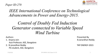
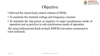
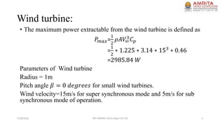
The document presents a control scheme for Doubly Fed Induction Generators (DFIG) integrated with variable speed wind turbines, focusing on maintaining terminal voltage and frequency stability. It includes the proposed control algorithm, simulation results, and discusses the impact of wind energy variations on energy conversion. The conclusion highlights reduced complexity in rotor-side converter control and improvements in grid synchronization using fuzzy logic techniques.