This research investigates the modeling and control of a doubly fed induction generator (DFIG) driven by wind turbines, focusing on optimizing power capture through a maximum power point tracking (MPPT) algorithm. The system's performance is validated through real-time simulations using a dSPACE DS1104 controller board integrated with MATLAB/Simulink. Key approaches include indirect field-oriented control (IFOC) with PI controllers to ensure effective control over the power generated regardless of wind speed variations.
![International Journal of Power Electronics and Drive System (IJPEDS)
Vol. 10, No. 2, June 2019, pp. 1003~1013
ISSN: 2088-8694, DOI: 10.11591/ijpeds.v10.i2.pp1003-1013 1003
Journal homepage: http://iaescore.com/journals/index.php/IJPEDS
Performance of a vector control for DFIG driven by
wind turbine: real time simulation using DS1104
controller board
Sara Mensou1
, Ahmed Essadki2
, Issam Minka3
, Tamou Nasser4
, Badre Bououlid Idrissi5
,
Lahssan Ben Tarla6
1, 2, 3 Electrical Engineering Department of ENSET Mohammed V University Rabat, Morocco
4 Department Communication Networks Department of ENSIAS Mohammed V University Rabat, Morocco
5, 6
Electromechanical Engineering Department of ENSAM Moulay Ismaïl University Meknès, Morocco
Article Info ABSTRACT
Article history:
Received Oct 7, 2018
Revised Feb 14, 2019
Accepted Mar 1, 2019
In this research paper we investigate the modelling and control of a doubly
fed induction generator (DFIG) driven in rotation by wind turbine, the
control objectives is to optimize capture wind, extract the maximum of the
power generated to the grid using MPPT algorithm (Maximum Power Point
Tracking) and have a specified reactive power generated whatever wind
speed variable, the indirect field oriented control IFOC with the PI correctors
was used to achieve such as decoupled control. To validate the dynamique
performance of our controller the whole system was simulated using
dSPACE DS1104 Controller board Real Time Interface (RTI) which runs in
Simulink/MATLAB software and ControlDesk 4.2 graphical interfaces.
Keywords:
DFIG
dSPACE card
Indirect field oriented control
MPPT method
Pulse with modulation
Wind turbine
Copyright © 2019 Institute of Advanced Engineering and Science.
All rights reserved.
Corresponding Author:
Mensou Sara,
Department of Electrical Engineering,
ENSET Mohammed V University Rabat, Morocco.
Email: sara.mensou11@gmail.com
1. INTRODUCTION
In recent years, the world has known a rapid evolution in various sectors that means the increase in
demand on electrical energy; The uses of traditional fossil and nuclear energy resources pollute the
environment, for this reasons countries are focused on development and exploitation of renewable energy
sources such as biomasses, wind energy and solar energy which can offer the opportunity to produce the
electrical energy in a clean way and help to save the environment [1]. Wind energy is one of the most
effective and clean resource, it presents a promising and important source of energy with low cost, so many
researchers have been focused on wind energy systems to develop new technologies in order to optimize the
capture wind and the electrical power produced [2, 4].
In wind farms the most installed generator is the Doubly-Fed Induction Generator DFIG, This
machine presents several advantages; it makes possible to better use the wind energy resources by offering a
large range variation of speed about ± 30% around the synchronous speed (hyper-synchronous and hypo-
synchronous mode) [4]. The power converters connected to the rotor are dimensioned to pass a fraction of the
nominal power produced by the generator (20%-30%), consequently, the reduction of losses in power
electronics converters and cost compared to others generators [3-6]. To optimize the performance and
effectiveness of the aero-generators and extract the maximum of the power generated to the network, several
solutions and control technologies have been studied in the literature [3-7].](https://image.slidesharecdn.com/4614feb1916390-28276-4-ededitulfah1-210624015811/85/Performance-of-a-vector-control-for-DFIG-driven-by-wind-turbine-real-time-simulation-using-DS1104-controller-board-1-320.jpg)
![International Journal of Power Electronics and Drive System (IJPEDS)
Vol. 10, No. 2, June 2019, pp. 1003~1013
ISSN: 2088-8694, DOI: 10.11591/ijpeds.v10.i2.pp1003-1013 1003
Journal homepage: http://iaescore.com/journals/index.php/IJPEDS
Performance of a vector control for DFIG driven by
wind turbine: real time simulation using DS1104
controller board
Sara Mensou1
, Ahmed Essadki2
, Issam Minka3
, Tamou Nasser4
, Badre Bououlid Idrissi5
,
Lahssan Ben Tarla6
1, 2, 3 Electrical Engineering Department of ENSET Mohammed V University Rabat, Morocco
4 Department Communication Networks Department of ENSIAS Mohammed V University Rabat, Morocco
5, 6
Electromechanical Engineering Department of ENSAM Moulay Ismaïl University Meknès, Morocco
Article Info ABSTRACT
Article history:
Received Oct 7, 2018
Revised Feb 14, 2019
Accepted Mar 1, 2019
In this research paper we investigate the modelling and control of a doubly
fed induction generator (DFIG) driven in rotation by wind turbine, the
control objectives is to optimize capture wind, extract the maximum of the
power generated to the grid using MPPT algorithm (Maximum Power Point
Tracking) and have a specified reactive power generated whatever wind
speed variable, the indirect field oriented control IFOC with the PI correctors
was used to achieve such as decoupled control. To validate the dynamique
performance of our controller the whole system was simulated using
dSPACE DS1104 Controller board Real Time Interface (RTI) which runs in
Simulink/MATLAB software and ControlDesk 4.2 graphical interfaces.
Keywords:
DFIG
dSPACE card
Indirect field oriented control
MPPT method
Pulse with modulation
Wind turbine
Copyright © 2019 Institute of Advanced Engineering and Science.
All rights reserved.
Corresponding Author:
Mensou Sara,
Department of Electrical Engineering,
ENSET Mohammed V University Rabat, Morocco.
Email: sara.mensou11@gmail.com
1. INTRODUCTION
In recent years, the world has known a rapid evolution in various sectors that means the increase in
demand on electrical energy; The uses of traditional fossil and nuclear energy resources pollute the
environment, for this reasons countries are focused on development and exploitation of renewable energy
sources such as biomasses, wind energy and solar energy which can offer the opportunity to produce the
electrical energy in a clean way and help to save the environment [1]. Wind energy is one of the most
effective and clean resource, it presents a promising and important source of energy with low cost, so many
researchers have been focused on wind energy systems to develop new technologies in order to optimize the
capture wind and the electrical power produced [2, 4].
In wind farms the most installed generator is the Doubly-Fed Induction Generator DFIG, This
machine presents several advantages; it makes possible to better use the wind energy resources by offering a
large range variation of speed about ± 30% around the synchronous speed (hyper-synchronous and hypo-
synchronous mode) [4]. The power converters connected to the rotor are dimensioned to pass a fraction of the
nominal power produced by the generator (20%-30%), consequently, the reduction of losses in power
electronics converters and cost compared to others generators [3-6]. To optimize the performance and
effectiveness of the aero-generators and extract the maximum of the power generated to the network, several
solutions and control technologies have been studied in the literature [3-7].](https://image.slidesharecdn.com/4614feb1916390-28276-4-ededitulfah1-210624015811/75/Performance-of-a-vector-control-for-DFIG-driven-by-wind-turbine-real-time-simulation-using-DS1104-controller-board-1-2048.jpg)
![ ISSN: 2088-8694
Int J Pow Elec & Dri Syst, Vol. 10, No. 2, June 2019: 1003 – 1013
1004
The objectives of this research paper is to extract the maximum of the electrical power generated
from the wind turbine for each wind speed variation and validate the dynamic performances of the system by
simulation using DS1104 Controller Card which runs in Simulink/MATLAB environment and ControlDesk
graphical interface. To control the generator we have used the PI controller for his easy maintenance, good
reliability and simplicity of implementation compared to other nonlinear controllers [3-4].
In this paper we start by the modeling of the wind energy conversion system; the modeling of the
wind turbine and the DFIG in the Park reference d-q, in the second section we present the indirect field
oriented control IFOC with the PI corrector to control the rotor side converter (RSC), then we present how to
extract the maximum of the power using the MPPT algorithm (Maximum Power Point Tracking), in the
fourth section the real time simulation results of the system using DS1104 card was presented, finally a
conclusions are given.
2. MODELING OF WIND ENERGY SYSTEM
The structure studied in this paper is based on the wind energy conversion system based on a doubly
fed induction generator with gearbox; the stator of the machine is connected directly to the network, while
the rotor is connected to the grid via two powers converters Figure 1.
Figure 1. The wind energy conversion system based on a DFIG
2.1. Wind turbine model
The modeling of the wind energy system is given by the following [6-7]:
3
3
3
2
( , ) . .
2
( , ) . .
2
p
aer
p
aer
aer
t t
S
P
C S
P
C S
P
T
(1)
The power coefficient Cp depending on the blade pitch angle β and the Tip Speed Ratio (TSR) λ are defined
as follows [7]:
21
3
116
( , ) 0.5176 0.4 5 0.0068
1 0.035
0.008 1
i
p
i
i
t
C e
R
(2)](https://image.slidesharecdn.com/4614feb1916390-28276-4-ededitulfah1-210624015811/85/Performance-of-a-vector-control-for-DFIG-driven-by-wind-turbine-real-time-simulation-using-DS1104-controller-board-2-320.jpg)
![Int J Pow Elec & Dri Syst ISSN: 2088-8694
Performance of a vector control for DFIG driven by wind turbine: real time simulation … (Sara Mensou)
1005
Where Pv, Paer , ρ, S, R, Ωt and v are the power of the wind turbine, the aerodynamic power
available on the rotor, the aerodynamic torque, the air density (ρ =1.22 kg/m3), the circular surface swept by
the turbine, the radius of the turbine, the turbine tpeed (rad/s) and the wind speed (m/s), respectively. The
fundamental equation of dynamics is given by [8-9]:
mec
g em f mec
d
J T T C
dt
(3)
Where Ωmec, J, Tg, Tem and Cf are the mechanical rotor speed (rad/s), the total inertia, the generator torque,
the electromagnetic torque and the coefficient of viscous friction, respectively.
2.2. Mathematical model of DFIG
The mathematical model of the stator and rotor voltages of the doubly fed induction generator in the
Park reference (d-q) is given by the following [10]:
sd
sd s sd sq s
sq
sq s sq sd s
rd
rd r rd rq r
rq
rq r rq rd r
d
V R I
dt
d
V R I
dt
d
V R I
dt
d
V R I
dt
(4)
sd s sd m rd
sq s sq m rq
rd s rd m sd
rq r rq m sq
L I L I
L I L I
L I L I
L I L I
(5)
Where Ls, Lr are the cyclic stator/rotor inductance, Lm is the maximum of the mutual inductance and Rs, Rr
are the stator/rotor resistance. The stator active/reactive powers & the electromagnetic torque of the DFIG are
given by [11-12]:
s sd sd sq sq
s sq sd sd sq
P V I V I
Q V I V I
(6)
3
2
m
em sq rd sd rq
s
L
T p I I
L
(7)
2.3. Converter model
The Rotor Side Converter (RSC) controlled by the Pulse with Modulation (PWM) signals is
modelled by a matrix. The matrix that connects the rotor voltages of the DFIG (Vra, Vrb, Vrc) and the control
signals provided from the PWM module (Sa, Sb, Sc) is constructed as follow [3]:
2 1 1
1 2 1
3
1 1 2
ra a
dc
rb b
rc c
V S
U
V S
V S
(8)
Where: Udc is the DC link Voltage.](https://image.slidesharecdn.com/4614feb1916390-28276-4-ededitulfah1-210624015811/85/Performance-of-a-vector-control-for-DFIG-driven-by-wind-turbine-real-time-simulation-using-DS1104-controller-board-3-320.jpg)
![ ISSN: 2088-8694
Int J Pow Elec & Dri Syst, Vol. 10, No. 2, June 2019: 1003 – 1013
1006
3. CONTROLLERS MODEL
3.1. Indirect field oriented control (IFOC)
To control the reactive power and the Torque of the generator (DFIG) independently we have to
apply the vector control in order to ensure a decoupling between the variables of the machine [13]. In this
paper, we chose a two phases d-q linked to the rotating reference frame, and the stator flux is oriented along
the axis d, the expression of the flux becomes [14]:
0
sd s
sq
(9)
Assuming that the flux stator is oriented along the axis d and constant at the permanent regime and
the stator resistance Rs of the generator is neglected, the equations of the stator and rotor voltages can be
expressed as [14-15]:
0
sd
sd s sd sq s
sq
sq s sq sd s s s
d
V R I
dt
d
V R I
dt
(10)
2 2
2 2
m rd m
rd r rd r r r rq
s s
rq
m m m
rq r rq r r r rd r s
s s s
L dI L
V R I L L I
L dt L
dI
L L L
V R I L L I
L dt L L
(11)
The expressions for the stator powers & the electromagnetic torque of the DFIG are given by [16]:
s m
s rq
s
s s s m
s rd
s s
V L
P I
L
V V L
Q I
L L
(12)
3
2
m
em s rq
s
L
T p I
L
(13)
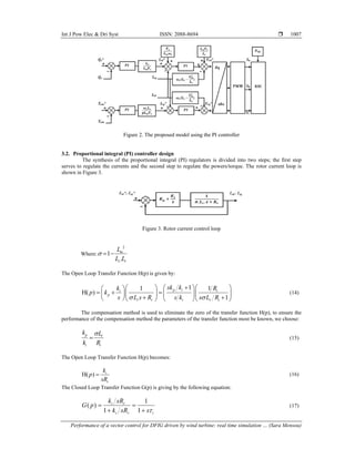
Fundamentally, the indirect field oriented method using the proportional integral correctors consists
of two control loops [2]. The first loop serves to calculate reference rotor currents (Irq*, Ird*), this control
loop gets its reference from the maximum power point tracking algorithm (MPPT) in order to optimize the
power produced from the generator for each wind speed changes. The second loop is used to determine the
rotor voltages references (Vrq*, Vrd*). According to (11), (12) and (13) we concluded that Vrd* and Vrq* are
the variables of the rotor voltages to impose on the DFIG to get the rotor currents, the electromagnetic torque
and the reactive stator power desired. The proposed model is given in Figure 2.](https://image.slidesharecdn.com/4614feb1916390-28276-4-ededitulfah1-210624015811/85/Performance-of-a-vector-control-for-DFIG-driven-by-wind-turbine-real-time-simulation-using-DS1104-controller-board-4-320.jpg)
![ ISSN: 2088-8694
Int J Pow Elec & Dri Syst, Vol. 10, No. 2, June 2019: 1003 – 1013
1008
Where r
i
i
R
k
; for the rotor current control loop we set the response time τi =1ms in order to have
a good tracking. Finally, we get: r
i
i
R
k
and r
p
i
L
k
. We used the same steps to calculate the gain of the
power/torque correctors. We get:
1
ii
i
k
and
r
pp
i i
R
k
k
.
3.3. Maximum power point tracking (MPPT Control)
To extract the maximum power generated it is necessary to provide the adequate electromagnetic
torque which is used to vary the mechanical rotor speed of the DFIG for each wind speed variation [6]. In
order to estimate the value of the wind speed which gives the maximum of the power we can fixed the TSR
to its optimum value λopt that corresponds to the maximum power coefficient Cp-max, According to (1) and
(2) it’s can be possible to deduce the expression of the reference electromagnetic torque as a function of the
optimum TSR λopt and mechanical rotor speed Ωmec [3-6]:
5
2
max 3
1 . .
( , )
2 ( . )
emref p mec
opt
R
T C
G
(18)
Where G is the gain of the multiplier wich adjusts the turbine speed to the rotor speed of DFIG. The block
diagram in Figure 4 presents the model of the turbine and the MPPT Algorithm.
Figure 4. Block diagram of the MPPT Method
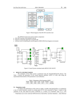
4. DSPACE DS1104 CONTROLLER BOARD
The dSPACE DS1104 Controller card is a cost effective system with a real time processor, it can be
mounted in a personal computer with a 5V PCI slot. The function models are easily turned on the DS1104
system with Real Time Interface (RTI), to configure the Input & Output of the system studied graphically the
ControlDesk interface can be used, insert the blocks diagrams and generate the model code via SIMULINK
software; the real time simulated models are compiled, downloaded, and started automatically [17]. This
increases systematically the productivity and reduces development costs and times. Figure 5 shows the block
diagram of the DS1104 Controller Card used in our laboratory which consists of a main processor PowerPC
64-bit floating point processor with a CPU Clock 250 MHz, a slave DSP I/O and a master PPC I/O
subsystem [17-18]. Figure 6 presents the model of the Control System under DS1104 RTI1104 which runs in
SIMULINK.](https://image.slidesharecdn.com/4614feb1916390-28276-4-ededitulfah1-210624015811/85/Performance-of-a-vector-control-for-DFIG-driven-by-wind-turbine-real-time-simulation-using-DS1104-controller-board-6-320.jpg)
![ ISSN: 2088-8694
Int J Pow Elec & Dri Syst, Vol. 10, No. 2, June 2019: 1003 – 1013
1012
ACKNOWLEDGEMENTS
This work is supported by: ENSET, Mohammed V University Rabat, Morocco. The authors would like to thank
all researchers and professors of the Electromechanical Engineering Department of ENSAM Moulay Ismaïl University
Meknès, Morocco.
REFERENCES
[1] B. Beltran, T. Ahmed Ali, M. Benbouzid, “Sliding Mode Power Control of Variable Speed Wind Energy
Conversion Systems”, IEEE Transl. Energy Conversion, vol. 23, pp. 551-558, June 2008.
[2] N. Bouchiba, A. Barkia, L. Chrifi Alaoui, S. Drid, S. Sallem, & M. B. A. kammoun, “Real-Time Integration of
Control Strategies for an Isolated DFIG -based WECS”, The European Physical Journal Plus, Vol. 132, No. 8, pp.
334-344, 2017.
[3] S. Mensou, A. Essadki, T. Nasser, B. B. Idrissi, “An Efficient Nonlinear Backstepping Controller Approach of a
Wind Power Generation System Based on a DFIG”. International Journal of Renewable Energy Research, Vol.7,
No 4, pp. 1520-1528, December 2017.
[4] M. El Azzaoui, H. Mahmoudi, K. Boudaraia, “Backstepping Control of wind and photovoltaic hybrid Renewable
Energy System”.International Journal of Power Electronics and Drive Systems (IJPEDS),Vol.7, pp. 677-686,
2016.
[5] B. Bossoufi, M. Karim, A. Lagrioui, & all, “Observer Backstepping Control of DFIG-Generators for Wind
Turbines Variable Speed: FPGA-Based Implementation”. Renewable Energy, Elsevier, Vol. 81, pp. 903-917, 2015.
[6] R. Chakib, A. Essadki, M. Cherkaoui, “Modeling and Control of a Wind System based on a DFIG by Active
Disturbance Rejection Control”, International Review on Modeling and Simulations, Vol. 7, pp. 626-637, 2014.
[7] D. R. Robinett III, G. D. Wilson, “Nonlinear Power Flow Control Design: utilizing exergy, entropy, static and
dynamic stability, and lyapunov analysis”, Springer Science & Business Media, 2011.
[8] F. Senani, A. Rahab, & H. Benalla, ”A Complete Modeling and Control for Wind Turbine Based of a Doubly Fed
Induction Generator using Direct Power Control”. International Journal of Power Electronics and Drive Systems
(IJPEDS), Vol. 8, No. 4, pp. 1954-1962, 2017.
[9] A. Rahab, F. Senani, & H. Benalla,“Direct power control of brushless doubly-fed induction generator used in wind
energy conversion system”. International Journal of Power Electronics and Drive Systems (IJPEDS), Vol. 8, No.
1, pp. 417-433, 2017.
[10] S. Mensou, A. Essadki, I. Minka, T. Nasser & B. B. Idrissi, “Backstepping Controller for a Variable Wind Speed
Energy Conversion System Based on a DFIG”, Proceeding of the 5th International Renewable and Sustainable
Energy Conference (IRSEC), December 2017.
[11] N. El Ouanjli, A. Derouich, A. El Ghzizal, Y. El Mourabit, B. Bossoufi & M. Taoussi, “Contribution to the
Performance Improvement of Doubly Fed Induction Machine Functioning in Motor Mode by the DTC Control”
International Journal of Power Electronics and Drive Systems (IJPEDS), Vol. 8, No. 3, pp. 1117-1127, September
2017.
[12] I. Minka, A. Essadki, S. Mensou & T. Nasser “Power Control of a DFIG Driving By Wind Turbine: Comparison
Study Between ADRC and PI Controller”, Proceeding of the 5th International Renewable and Sustainable Energy
Conference (IRSEC), December 2017.
[13] Z. Mekrini, S. Bri, “Performance of an Indirect Field Oriented Control for Asynchronous Machine”, International
Journal of Engineering and Technology, vol. 8, pp. 726-733, Apr-May 2016.
[14] K. Ghedamsi, E.M. Berkouk, “Control of Wind Generator Associated to a Flywheel Energy Storage System”,
Renewable Energy, Elsevier, Vol. 33, pp. 2145-2156, 2008.
[15] S. Mensou, A. Essadki, T. Nasser & B. B. Idrissi, “A Robust Speed Control of a Doubly Fed Induction Generator
Using in WECS by the Nonlinear Backstepping Controller”. Proceeding of the 3rd International Conference
on Electrical and Information Technologies (ICEIT), pp. 1-6, November 2017.
[16] Y. Ihedrane, C. El Bekkali, B. Bossoufi, “Improved Performance of DFIG-generators for Wind Turbines Variable-
speed”, International Journal of Power Electronics and Drive Systems (IJPEDS), Vol. 9, No. 4, pp. 1875-1890,
December 2018.
[17] Z. A. Ghani, M. A. Hannan, & A. Mohamed, “Renewable Energy Inverter Development Using dSPACE DS1104
Controller Board”. Proceeding of the IEEE Conference on Power and Energy, pp. 69-73, November 2010.
[18] C.R. Bala Murugan, S.P. Natarajan, R. Bensraj, “Dspace Based Implementation of Various Inverted Sine Carrier
PWM Strategies for Three Phase Five Level H-Bridge Inverter”, International Journal of Advanced Engineering
Technology, Vol.7, pp.103-112, March 2016.](https://image.slidesharecdn.com/4614feb1916390-28276-4-ededitulfah1-210624015811/85/Performance-of-a-vector-control-for-DFIG-driven-by-wind-turbine-real-time-simulation-using-DS1104-controller-board-10-320.jpg)