Downloaded 2,617 times
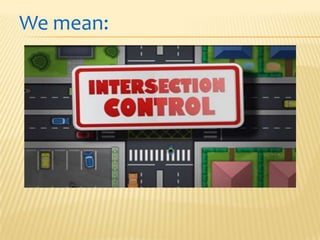
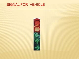
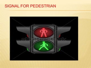
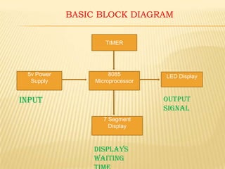
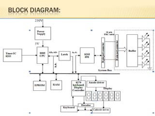
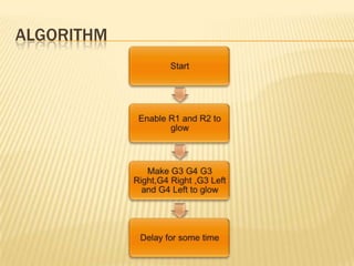
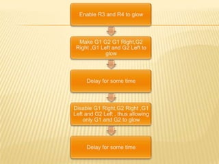
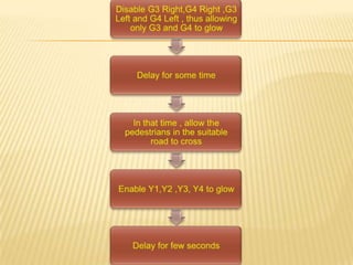
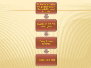
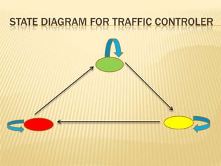
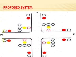
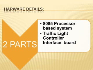
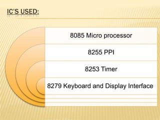
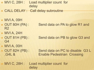
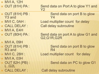
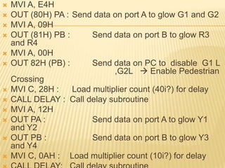
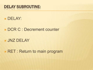
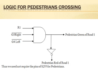
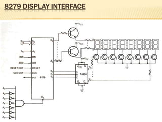
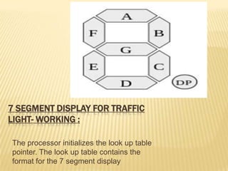
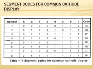


The document describes a traffic light control system using an 8085 microprocessor. It discusses the need for a traffic light system, describes the basic components including colors and signals. It then covers the hardware details of the 8085-based system and interface board, including ICs used. Algorithms and state diagrams are presented to show the logic for controlling lights and pedestrians.